Note: Descriptions are shown in the official language in which they were submitted.
CA 02408128 2002-11-05
WO 01/85421 PCT/GBO1/02051
1
EXPANDED PLASTICS CONTAINERS
The present invention relates to containers moulded from expanded
plastics material, such as expanded polystyrene, and more particularly to
expanded plastics containers designed to be fitted with snap-on lids,
typically,
moulded from sheet plastics material.
Expanded or foam plastics containers are conventionally formed by
depositing beads or particles of a suitable plastics material into a mould
cavity
defining the desired shape of the container and injecting steam into the mould
cavity to "cook" the plastics material. The beads comprise a thermoplastics
material and a foaming agent and the term "cook" and like terminology are the
terms commonly used to describe injecting steam directly into the beads
disposed
in the mould to achieve the necessary expansion and fusion of the beads for
producing the container moulding.
Hitherto, expanded plastics cups and similar containers designed to receive
lids have been moulded with relatively thick walls, for example, 2.2mm thick,
and
with the side wall of the container flared outwardly at the mouth to provide a
rim
portion capable of capturing a lid. The rim, itself, is rounded and because
the rim
portion is of generally the same thickness as the container side wall and is
flared
outwardly, the lid can resiliently engage over the rim, in an interference fit
rather
than with a positive, snap-on fit, and be captured by the rim.
This form of construction has previously been used for expanded plastics
containers because it has proved difficult to mould such a container with a
true rim
flange for capturing a snap-on plastic lid, similarly to the roll type rim
flange of a
cup thermoformed from sheet plastics material.
Because such prior containers are relatively thick walled, when stacked in
nested relation for the purposes of storage and transportation, the stack also
tends to be undesirably lengthy. Moreover, the low density foam material
forming
the containers results in poor surface smoothness, thereby making it difficult
to
provide for acceptable printing of advertising and other matter on the
external
walls of the containers.
An object of the present invention is to provide a method and apparatus for
moulding an expanded plastics container with a rim flange which projects
radially
outwardly about the mouth of the container, similarly to the roll type rim
flange of a
CA 02408128 2002-11-05
WO 01/85421 PCT/GBO1/02051
2
cup thermo-formed from sheet plastics material, and which is capable of
capturing
a snap-on lid.
From one aspect, therefore, the invention consists in a method of moulding
an expanded plastics container with a rim flange projecting outwardly from the
container side walls) about the mouth of the container, comprising the steps
of
disposing plastics material adapted for moulding an expanded product into a
mould cavity defining the container to be moulded with the rim flange,
introducing
steam into the mould cavity to cook the plastics material and mould the
expanded
plastics container, and additionally directing steam into the mould cavity at
or
adjacent the rim flange moulding zone.
The invention enables the moulding of an expanded plastics container
which is a thin wall product formed from expanded plastics material of higher
density than hitherto used in such products and which incorporates a roll type
rim
flange to accommodate a snap-on lid. With the invention, the container may,
for
example, have a wall thickness of 1.4mm. Moreover, the thin walled nature of
the
container enables a significant reduction in the height of a stack of such
containers, when stacked in nested relation, and the increased density of the
moulded plastics material results in a smoother surface finish which permits
the
application of full cover printing to a more acceptable quality and to a
quality not
possible with prior expanded plastics containers designed for accommodating
lids.
Furthermore, the invention enables the production of a laminated product in
which a laminate of flexible sheet material which may be printed on its
outside
surtace and which may be a sleeve, or foldable into a sleeve, for surrounding
the
periphery of the container, optionally, for the full height of the container
periphery,
is adhered to the external surface of the container during the moulding
process. In
a preferred embodiment, the laminate has a heat activated adhesive layer and
is
positioned in the mould cavity directly against the mould wall defining the
external
wall of the container, whereby the external laminate is laminated with the
expanded plastics material and with the external wall of the container during
the
moulding process. When seated directly under the rim flange of the container,
the
upper edge of the laminate is concealed.
Typically, an expanded plastics container is moulded with the mouth of the
container directed downwardly and its bottom wall uppermost. Steam for cooking
CA 02408128 2002-11-05
WO 01/85421 PCT/GBO1/02051
3
the raw plastics material is introduced or injected into the mould cavity
adjacent
the bottom wall. Cavities, which are alternatively flushed with steam to heat
the
mould during the cook cycle and with cooling liquid to cool the mould at the
end of
the cook cycle, may be provided adjacent the inside and outside of the mould
cavity. In a preferred embodiment, the method of the invention may be realised
by redirecting part of the steam utilised to flush one of the cavities during
the cook
cycle into the mould cavity at or adjacent the rim flange (e.g. just below the
rim
flange) of the container moulding, thereby to provide an additional or rim
cook
facility. Optimum results are achieved by redirecting the steam for this rim
cook
facility into the mould cavity at a location as close as possible to the rim
flange
moulding.
The present invention also consists in a mould tool for moulding an
expanded plastics container having a rim flange projecting outwardly from the
container side walls) about he mouth of the container, said mould tool
comprising
male and female mould parts which are assembled to form a mould cavity
defining
the container having the rim flange, at least one cavity for heating and/or
cooling
fluid in at least one of the mould parts adjacent the mould cavity and
extending
adjacent at least that part of the cavity defining the side walls) of the
container,
conduit means for supplying steam to the heating/cooling cavity, first
passageway
means via which steam is injected into the mould cavity, second passageway
means for directing a portion of the flushing steam from the heating/cooling
cavity
into the mould cavity at or adjacent the rim flange moulding zone of the mould
cavity, and valve means for controlling flow of steam via said second passage
means.
In one embodiment, the container is moulded in an inverted position with its
mouth downwardly and steam for cooking plastics material is injected at the
upper
end of the mould adjacent the bottom wall of the container. The mould tool may
include a male mould part comprising a core section and an outer shell fitted
over
the core section so as to provide a heating/cooling cavity within the outer
shell.
The outer surface of shell moulds the internal surface of the container and
the
heating/cooling cavity may be substantially coextensive with the shell. The
male
mould part cooperates with a female mould part assembled over the male mould
CA 02408128 2002-11-05
WO 01/85421 PCT/GBO1/02051
4
part to define the mould cavity. The female mould part may comprise an inner
female shell which moulds the external wall of the container and a top mould
member fitted over the outside of the female shell so as to provide a
heating/cooling cavity substantially coextensive with the female shell and
about
the outside of the mould cavity. Suitable conduits are arranged to supply
flushing
steam or cooling liquid to the heating/cooling cavities. One of these conduits
is
connectable, under control of first valve means, to first passageways means
communicating with the upper end of the mould cavity to permit steam to be
injected into the mould to cook the moulding material. One of the
heating/cooling
cavities is connectable, via second passageway means controlled by second
valve means, to the mould cavity at a position adjacent the bottom of the
mould
cavity and adjacent the rim zone to provide the additional cook facility for
the rim
flange moulding.
Upon reassembly of the mould tool preparatory to moulding another
container, and following cooling and ejection of the previous moulded
container,
the heating/cooling cavities are flushed with steam to reheat the mould and
the
first valve means is actuated to inject steam into the mould cavity, via the
first
passageway means, to cook the plastics beads in the mould cavity and, during
the cooking cycle, the second valve means is opened to redirect part of the
steam
flushing the heating/cooling cavity to the rim moulding area of the mould
cavity to
provide the additional cook facility.
Each passageway means may be connected, via ports, to an annular
groove in the moulding surface of the relevant mould shell to assist
distribution of
the stream about the mould cavity, and a flexible ring seal is located within
the
annular groove. This ring seal is profiled in such a way as to allow steam
under
pressure to pass over the seal into the mould cavity but prevents the ingress
of
bead particles which may block the steam ports.
In order the present invention may be more readily understood, reference
will now be made to the accompanying drawings, in which:-
Figure 1 is a half sectional, half-elevational view of an expanded plastics
cup produced by the method of the invention,
Figure 2 is an axial section illustrating an assembled mould tool according
to the invention and ancillary couplings for producing the cup shown in Figure
1,
CA 02408128 2002-11-05
WO 01/85421 PCT/GBO1/02051
Figure 3 is an axial section through the assembled mould tool of Figure 2
on an enlarged scale,
Figure 4 is a fragmentary axial section illustrating the rim zone of the mould
tool, and
5 Figures 5 and 6 are fragmentary sectional views illustrating the annular
grooves and flexible ring seals via which steam is injected into the mould
cavity of
the mould tool.
Referring to Figure 1 of the accompanying drawings, the expanded or foam
plastics cup 10 produced by the method and mould tool of this invention may be
moulded from expanded polystyrene material. The resulting moulding is a thin
walled product of high density foam plastics material. It is of circular shape
in plan
and comprises a bottom wall 11 and a side wall 12 extending upwardly and
outwardly from the bottom wall to a mouth 13 at the top of the cup where the
side
wall terminates in an annular rim flange 14 which projects radially outwardly
from
the side wall about the mouth of the container. The rim flange 14 is similar
to the
roll-type rim flange of a cup thermoformed from sheet plastics material and is
designed for capturing a lid which may be snapped onto the rim flange to close
the mouth of the container. A multiplicity of such cups may be stacked in
nested
relation and to prevent them from wedging together, when so stacked, making
the
cups difficult to separate from the stack, the cup 10 is moulded internally
adjacent
its bottom wall with an annular internal stacking shoulder 15 which engages
with
the periphery of the bottom wall 11 of an upper cup nested therein in order to
resist compression of the inner cup into the outer cup.
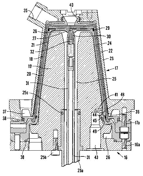
Referring to Figures 2, 3 and 4, the mould tool for producing the cup 10
illustrated in Figure 1 moulds the cup with its bottom wall 11 uppermost and
its
mouth 13 directed downwardly. The tool comprises male and female mould parts
16,17 which are assembled to form a mould cavity 18 for the cup 10 to be
moulded. The male mould part 16 has a core section 19 and an outer shell 20
fitted over the core section so as to leave a heating/cooling cavity 21
between the
outer shell and the core section. The external surface of the outer shell
forms a
moulding surtace for the internal surtaces of the bottom and side walls of the
cup
10 and the heating/cooling cavity 21 is substantially coextensive with the
bottom
and side walls of the mould cavity. The female mould part 17 comprises an
inner
CA 02408128 2002-11-05
WO 01/85421 PCT/GBO1/02051
6
female shell 22 which moulds the external surfaces of the bottom and side
walls of
the cup and a top mould member 23 which is fitted over the outside of the
female
shell so as to provide a heating/coofing cavity 24 between the female shell
and
the top mould member. This outer heatinglcooling cavity is substantially
coextensive with the bottom and side walls of the mould cavity. At the bottom
end
of the mould cavity 18, the outer shell 20 of the male mould part and the
inner
female shell 22 define the radially outwardly projecting rim flange 14 to be
moulded about the mouth of the cup.
The core section and outer shell of the male mould part 16 are secured
together at the bottom end of the mould tool by machine screws 16a and the
inner
female shell and the top mould member of the female mould part 17 are secured
together by machine screws 17a. 0-ring seals 38 are disposed between the
components of the mould parts, at appropriate positions, to seal the
components
together.
Extending centrally through the male core section 19 to a position adjacent
the upper end thereof is a central conduit 25 via which flushing steam for
heating
the mould during the cook cycle or cooling liquid for cooling the mould at the
end
of the cook cycle is alternatively supplied to the inner cavity 21. Flushing
steam or
cooling liquid is delivered to the conduit 25 by a pipe 25a coupled to the
male core
section by machine screws 25b and sealed to the conduit by an 0-ring seal 25c.
It exits the cavity 21 via an annular outlet 26 adjacent the bottom end of the
mould
tool. At its upper end, the conduit 25 is connected, via a valve port 27 to
diametrically disposed passageways 28 communicating with the mould cavity 18
via an annular groove 29 (Figure 5) in the outer surface of the outer shell
20. The
valve port 27 is controlled by a spring loaded valve member 30 disposed at the
upper end of the conduit 25 and actuated by a hollow valve rod 31 projecting
through the conduit to a suitable pneumatic actuating mechanism 31 a. The
valve
member 30 has an axial passageway 32 connected to the hollow actuating rod 31
to permit compressed air to be supplied through the rod, the valve member and
the passageways 28 into the mould cavity so as to assist in ejecting a moulded
cup from the mould cavity 18 at the end of the moulding cycle.
As illustrated in Figures 5 and 6, the annular groove 29 is fitted with a
flexible ring seal 33 which is profiled in such a way as to allow steam under
CA 02408128 2002-11-05
WO 01/85421 PCT/GBO1/02051
7
pressure to pass over the seal into the mould cavity but prevents the ingress
of
moulding beads 34 which may block the ports.
Flushing steam and cooling liquid are alternatively supplied to the outer
heating/cooling cavity 24 via a port 35 in the top mould member 23, which port
is
connected to a suitable supply conduit (not shown). They exit from the cavity
via
an annular outlet 36 and annular manifold 37 adjacent the bottom end of the
mould cavity.
Beads of a suitable moulding material for the cup, and comprising a
thermoplastics material and a foaming agent, are supplied to the mould cavity
through a conduit 39 coupled to the top mould member 23 by a coupling unit 52
bolted to the top mould member by machine screws 53 and connected to a funnel
shaped port 40 in the inner female shell 22 which communicates with the mould
cavity. Delivery of moulding beads to the mould cavity is assisted by the
supply of
compressed air through the air nozzle 54 also coupled to the port 40 by the
coupling unit 52. Furthermore, compressed air is supplied to this nozzle when
the
mould parts 16 and 17 are separated at the end of a moulding cycle in order to
retain the moulded cup on the male mould part preparatory to ejection from the
tool.
Connected to the inner heating/cooling cavity 21 adjacent the bottom end
of the male core section 19 is a passageway 41 which connects the bottom end
of
the heating/cooling cavity to a valve port 42 communicating with the end of a
valve chamber 43. A second valve port 44 communicating with the valve chamber
connects the latter to a circular cavity 45 in the male core section 19 and,
in turn,
the cavity 45 is connected, via a port 46 through the male outer shell 20 to
an
annular groove 47 (Figure 5) in the outer surface of the shell above and
immediately adjacent the rim flange moulding zone. The circular cavity 45
houses
an 0-ring seal 48 for sealing the ports 44,46 against the ingress of flushing
steam
and cooling liquid from the cavity 21. The annular groove 47 is like the
groove 29
and is similarly fitted with a ring seal 49 corresponding to the ring seal 33
and
profiled in such a way as to allow steam under pressure to pass over the seal
into
the mould cavity but prevent the ingress of bead particles (see Figures 5 and
6).
The valve ports 42,44 are controlled by a valve member 50 (Figure 2) slidably
mounted in the bottom end of the core section 19 and projecting into the valve
CA 02408128 2002-11-05
WO 01/85421 PCT/GBO1/02051
8
chamber 43. The valve member 50 is controlled by a spring loaded, pneumatic
piston 51.
In order to mould an expanded plastics cup, the female mould part 17 is
assembled to the male mould part 16, as illustrated in Figures 3 and 4, and
plastics moulding beads or particles are injected into the mould cavity 18 via
the
funnel shaped port 40 in the female shell 22. When the mould cavity is full,
steam
is injected through the conduit 25 and the port 35 in order to flush the inner
and
outer cavities 21,24 with steam and thereby heat the mould. At the appropriate
time in the moulding cycle, the pneumatically operated valve rod 31 is
actuated in
order to withdraw the valve member 30 and permit steam to enter the mould
cavity 18 via the port 27, the passageways 28 and the annular groove 29 in
order
to cook the plastic beads in the mould cavity. Also, the pneumatically
controlled
valve member 50 is actuated in order to open the ports 42,44 and redirect
steam
from the inner heating/cooling cavity 21, adjacent its bottom end, into the
rim zone
of the moulding so as to deliver steam directly to the rim zone and provide a
secondary cooking effect which facilitates moulding of the outwardly directed
rim
flange 14.
At the end of the cook cycle, the valve members 27,50 are closed and
cooling liquid is supplied, via the conduit 25 and port 35, to the
heating/cooling
cavities 21,24 in order to cool the mould tool and the moulded cup, whereafter
the
male and female mould parts 16,17 are separated and compressed air is supplied
through the hollow valve rod 31 and valve member 30 to the passageways 28 in
order to blow air into the moulded cup and facilitate ejection of the cup from
the
male mould part.
The cup 10 produced by the above described process is a thin walled
product and a stack of such cups forms a stack of lesser height than the
equivalent number of cups of the thicker wall construction hitherto used for
expanded plastics cups designed to capture snap-on sheet plastic lids.
Moreover,
the higher density of the foam material used for moulding the present cup also
results in a product with a much smoother surface finish than the prior cups
and
this permits more acceptable printing of advertising and other material on the
walls of the cup.
CA 02408128 2002-11-05
WO 01/85421 PCT/GBO1/02051
9
In a modification, the moulding process may be used to produce a cup of
laminated construction in which a laminate of flexible sheet material, for
example,
paper or plastics sheet material printed on its outside surface with
advertising or
other matter, is laminated to the external surface of the cup side wall 12. In
this
modified process, which is fully described in our copending International
application (Attorney's reference No 35730) entitled "Production of Expanded
Plastics Containers" and filed concurrently herewith, a laminate formed of the
sheet material foldable about itself into a sleeve and of slightly conical
shape
matching the side wall of the cup, is disposed within the female mould part 17
against the inner surface of the female shell 22 prior to assembly of the
mould tool
for moulding a cup. The laminate may, for example, be formed from sheet
polypropylene material, and be provided on its inner surface with a heat
activated
adhesive and may extend for the fuN height of the side wall of the cup. The
edge
of the laminate adjacent the mouth of the cup is positioned directly below the
rim
flange moulding zone. Thereafter, the moulding process proceeds as described
above and the resulting product is a cup of laminated construction with the
laminate forming the outer surface of the cup and being seated directly under
the
rim flange so that its upper edge is concealed.
The method of producing a cup of laminated construction as described
above enables the production of an expanded plastics cup with high quality
printing on its surface whilst still retaining the heat insulating advantages
of
expanded or foam plastics material. The laminate also serves to strengthen or
reinforce the thin walled expanded plastics cup.
Whilst particular embodiments have been described, it will be understood
that modifications can be made without departing from the scope of the
invention
as defined by the appended claims.