Language selection

Search

Patent 2408257 Summary

Third-party information liability

Some of the information on this Web page has been provided by external sources. The Government of Canada is not responsible for the accuracy, reliability or currency of the information supplied by external sources. Users wishing to rely upon this information should consult directly with the source of the information. Content provided by external sources is not subject to official languages, privacy and accessibility requirements.

Claims and Abstract availability

Any discrepancies in the text and image of the Claims and Abstract are due to differing posting times. Text of the Claims and Abstract are posted:

  • At the time the application is open to public inspection;
  • At the time of issue of the patent (grant).
(12) Patent: (11) CA 2408257
(54) English Title: STUD WELDING HEAD
(54) French Title: TETE DE SOUDAGE DE GOUJONS
Status: Term Expired - Post Grant Beyond Limit
Bibliographic Data
(51) International Patent Classification (IPC):
  • B23K 9/20 (2006.01)
(72) Inventors :
  • MADSAK, JURGEN (Germany)
  • CITRICH, ULRICH (Germany)
(73) Owners :
  • AVISTUD GMBH
(71) Applicants :
  • NELSON BOLZENSCHWEISS-TECHNIK GMBH & CO. KG (Germany)
(74) Agent: GOWLING WLG (CANADA) LLP
(74) Associate agent:
(45) Issued: 2010-06-29
(86) PCT Filing Date: 2001-02-21
(87) Open to Public Inspection: 2001-08-30
Examination requested: 2006-01-17
Availability of licence: N/A
Dedicated to the Public: N/A
(25) Language of filing: English

Patent Cooperation Treaty (PCT): Yes
(86) PCT Filing Number: PCT/DE2001/000683
(87) International Publication Number: WO 2001062427
(85) National Entry: 2002-11-06

(30) Application Priority Data:
Application No. Country/Territory Date
200 03 132.5 (Germany) 2000-02-21

Abstracts

English Abstract


The invention relates to a stud welding head with a linear drive (5), a
welding pin (11) coupled with said linear drive (5), and a length metering
system (7) that determines the position of the welding pin (11) in the stud
welding head, said length metering system (7) being an electromagnetic length
metering system.


French Abstract

L'invention concerne une tête de soudage de goujons comportant un organe d'entraînement linéaire (5), un axe de soudage (11) accouplé à ce dernier (5), et un système de mesure de longueur (7) électromagnétique qui détermine la position de l'axe de soudage (11) dans la tête de soudage de goujons.

Claims

Note: Claims are shown in the official language in which they were submitted.

Patent Claims
1) Stud welding hand with a linear drive (5), with a welding aide (11),
coupled with the
linear drive (5); and with a length measuring system (7), which determines the
position of
the welding axle (11) in the stud welding head, is thereby determined
that the length measuring system (7) is an electromagnetic length measuring
system,
which features a magnet sensor (33) and a multitude of ordered linear
permanent magnets
in the direction of the welding axle's movement (11).
2) According to claim 1, the stud welding head is thereby characterized that
an
incremental length measuring system is designated.
3) According to claim 1 or 2, the stud welding head is thereby characterized
that the
permanent magnets are provided on or in a tape and they form a magnetic tape
(31).
4) Stud welding head in accordance with the preceding claims is thereby
characterized
that permanent magnets or a magnetic tape (31) era attached to a welding axle
(11).
5) Stud welding head in accordance with the preceding claims is thereby
characterised
that a length measuring systems has a modifiable resolution.
6) Stud welding head in accordance with the preceding claims is thereby
characterized
that a linear drive (5) is designated, which works according to the moving
coil principle.
7) According to claim 6, the stud welding head is thereby characterized that a
linear drive
(5) features several series-connected coils (9, 9'), in which is attached at
least one
permanent magnet, coupled with a welding axle (11).

Description

Note: Descriptions are shown in the official language in which they were submitted.


CA 02408257 2002-11-06
WO 01 //62427 1 PCT/DE01 /00683
Stud Welding Head
The invention concerns a stud welding head with a linear drive, a welding pin
coupled with the linear drive, and a length measuring system that determines
the
position of the welding pin in the stud welding head.
Stud welding devices are, for example, used in the automobile industry to weld
studs to the body of a car. The welding occurs in that a high voltage is
applied
between the studs secured in the welding head and the work piece and in that
an
electric arc is created. The positioning of the welding stud, namely the
lifting of
the welding stud and the creation of the electric arc as well as the
subsequent
dipping of the stud into the welding deposit should ensure that a consistently
high
weld quality is always achieved. Until now, only optoelectronic length- or
distance-measuring systems have been used. These are sensitive with respect
to the high welding currents and the corresponding magnetic fields. Strong
magnetic fields can be created in stud welding heads also in the area of the
linear drive; since the linear drives often operate according to the moving
coil
principle, i.e., they have current-carrying coils and permanent magnets. The
optoelectronic length measuring systems are, however, temperamental with
respect to dirt. Since a large number of welding jets are created in the area
of the
welding head and the environment is often very dusty, the previously used
optoelectronic distance measuring systems are sealed in the welding head,
which requires a lot of work.
The invention establishes a stud welding head, which is distinguished by its
simple construction, and the length measuring system of which offers an even
better resolution than the previously used length measuring system.
This is achieved for a stud welding head of the type named above in that the
length measuring system is an electromagnetic length measuring system.

CA 02408257 2002-11-06
WO 01 //62427 2 PCT/DE01 /00683
Practical experience has shown that electromagnetic length measuring systems,
which are sensitive to dirt out of principle, are able to function in stud
welding
heads. This is completely surprising for an expert, since extremely high
welding
currents flow in the stud welding heads and, as a result, strong
electromagnetic
fields are created. As it turns out, resolutions, which are much higher than
those
in optoelectronic length measuring systems, can also be achieved in welding
heads by electromagnetic length measuring systems.
In accordance with the preferred design, an incremental length measuring
system with a magnetic band and a magnetic sensor is used, whereby the
magnetic band is affixed to the welding pin. Due to the provision of a
magnetic
band, the effort required to fasten the band to the welding pin is low.
Moreover, the length measuring system can have an adjustable resolution in
order to be able to adjust it based on conditions and requirements.
Alternatively, an inductive length measuring system is also used.
The preferred design uses a linear drive that functions according to the
moving
coil principle and has several series-connected coils, into which at least one
permanent magnet extends, which is coupled with the welding pin. This type of
linear drive has the advantage that it can achieve an exact positioning of the
welding pin and is ideally supplemented with the electromagnetic length
measuring system, which has a high resolution. Since this type of linear drive
also creates extremely strong magnetic fields, it is all the more astonishing
that
an electromagnetic length or distance measuring system, in particular with the
use of a magnetic band and an inductive magnetic sensor, functions highly
accurately and is also stable in the long-term.

CA 02408257 2002-11-06
WO 01!/62427 3 PCT/DE01/00683
Additional characteristics and advantages of the invention ensue from the
following description and from the following drawing, to which reference is
made.
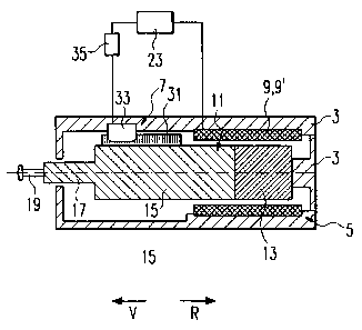
Fig. 1 shows a longitudinal-section view through the stud welding head in
accordance with the invention; and
Fig. 2 shows a schematic diagram of the linear drive of the stud welding
head in accordance with Figure 1.
In Figure 1, a stud welding head is portrayed that has a housing 3; an
electromagnetic, axial-operative linear drive 5 located in housing 3; and an
electromagnetic length or distance measuring system 7. The linear drive 5
consists of several cylindrical coils 9, 9' (see Figure 2) that are affixed to
housing
3 and a welding pin 11 that extends into the interior of coils 9, 9' but that
also
projects from them. The welding pin 11, on the other hand, consists of several
sections, namely a rear section 13 in the form of one or more successively
arranged permanent magnets and a connected, stretched-out cylindrical section
15, which has a front end that is designed as a stud holder. A stud 19 to be
welded is inserted and secured in the stud holder 17.
The stud welding head displayed in Figure 1 works as follows:
The stud welding head is applied to a non-portrayed work piece, for example, a
vehicle sheet metal. During the application of the welding head, which is
affixed
to a robot arm, the welding pin 11 can be in the starting position shown in
Figure
1. When the robot has affixed the welding head to the work piece, the welding
pin
11 is moved in the advance direction V, until the tip of the welding stud 19
comes
in contact with the surface of the work piece. In this position, the location
of the
work piece can be determined.

CA 02408257 2002-11-06
WO 01//62427 4 PCT/DE01/00683
After the work-piece surface has been contacted, the welding voltage is
applied
and the drive pin 11 proceeds in a distance- or velocity-driven manner in a
defined route in direction R to a desired or interim position so that the
electric arc
is generated by means of stroke firing. In order to obtain high-quality
standards
during welding, it is necessary that the distance between the work piece and
the
welding stud is kept as constant as possible, which is easy to achieve by
means
of the high-resolution, incremental length measuring system in combination
with
the special linear drive 5. For this reason, linear drive 5 and the length
measuring
system are described below in more detail.
The linear drive 5, which functions in accordance with the moving coil
principle,
can have, as shown in Figure 2, several coifs, for example two coils 9, 9'
connected in a row with different winding directions, so that two
electromagnets
with opposite magnetic flow directions are created; as described, for example,
in
US 5 321 226. The permanent magnet on rear section 13 projects into both coils
9, 9' and can be moved in both directions through coils 9, 9'.
The length measuring system 7 is there to determine the location of the drive
pin
11 and is connected with a control module 23, which, on the other hand, also
controls the welding current and coils 9, 9'.
The electromagnetic length measuring system 7 consists of a magnetic band 31,
which is affixed to welding pin 11, for example using glue, and a magnetic
sensor
33 affixed to housing 3. The resolution of the length measuring system can be
set, for example in the range from 1 mm to 0.005 mm, via a rotating coding
circuit
35.
The magnetic band 31 includes a number of linearly arranged permanent
magnets, for example in the form of bar magnets that are arranged with their
axis
diagonal to the longitudinal axis of the magnetic band. The permanent magnets

CA 02408257 2002-11-06
WO 01//62427 5 PCT/DE01/00683
can be embedded or injected into plastic. If necessary, the magnetic band can
be
strengthened with metal strips or wires. The permanent magnets are preferably
located equidistant from each other in the longitudinal direction of magnetic
band
31. For example, the distance between two permanent magnets can be approx. 2
mm.
The magnetic sensor (i.e., any type of sensor for the detection of magnetic
fields)
can be designed as an inductive sensor. If magnetic sensors 33 and magnetic
band 31 are moved relative to each other, then the magnetic sensor creates an
undulating signal. The signal is evaluated by an evaluation unit (not
portrayed
here) that, for example, can be integrated into control module 23, and, from
this,
the change in the position or the absolute position of the welding pin 11 is
determined. For example, the signal of the magnetic sensor can be scanned
equidistantly, and the position of the welding pin can be determined extremely
accurately from the information on the distance between two extremes of the
signal, which correlates with the distance between two permanent magnets in
the
longitudinal direction of the magnetic band, and from the signal value in the
scanning point, in reference to a peak value.
If drive pin 11 is finally moved in advance direction V by activation of
linear drive
5, this movement preferably occurs regularly (close loop feedback). Stud 19 is
dipped into the melt and affixed to the work piece. Of course, a controlled
movement without regulation would also be possible'.

Representative Drawing
A single figure which represents the drawing illustrating the invention.
Administrative Status

2024-08-01:As part of the Next Generation Patents (NGP) transition, the Canadian Patents Database (CPD) now contains a more detailed Event History, which replicates the Event Log of our new back-office solution.

Please note that "Inactive:" events refers to events no longer in use in our new back-office solution.

For a clearer understanding of the status of the application/patent presented on this page, the site Disclaimer , as well as the definitions for Patent , Event History , Maintenance Fee  and Payment History  should be consulted.

Event History

Description Date
Inactive: COVID 19 Update DDT19/20 Reinstatement Period End Date 2021-03-13
Inactive: Expired (new Act pat) 2021-02-22
Letter Sent 2020-08-31
Inactive: COVID 19 - Deadline extended 2020-08-19
Inactive: COVID 19 - Deadline extended 2020-08-06
Letter Sent 2020-02-21
Common Representative Appointed 2019-10-30
Letter Sent 2019-07-22
Inactive: Single transfer 2019-07-12
Letter Sent 2019-03-15
Inactive: Single transfer 2019-03-06
Change of Address or Method of Correspondence Request Received 2018-01-10
Inactive: Late MF processed 2012-02-27
Letter Sent 2012-02-21
Inactive: Late MF processed 2011-03-08
Letter Sent 2011-02-21
Grant by Issuance 2010-06-29
Inactive: Cover page published 2010-06-28
Pre-grant 2010-04-19
Inactive: Final fee received 2010-04-19
Letter Sent 2010-01-25
Notice of Allowance is Issued 2010-01-25
Inactive: Approved for allowance (AFA) 2010-01-21
Amendment Received - Voluntary Amendment 2009-05-11
Inactive: S.30(2) Rules - Examiner requisition 2008-11-12
Amendment Received - Voluntary Amendment 2008-05-06
Inactive: S.30(2) Rules - Examiner requisition 2007-11-06
Letter Sent 2006-01-24
All Requirements for Examination Determined Compliant 2006-01-17
Request for Examination Requirements Determined Compliant 2006-01-17
Request for Examination Received 2006-01-17
Letter Sent 2004-03-04
Inactive: Single transfer 2003-12-31
Inactive: Courtesy letter - Evidence 2003-02-11
Inactive: Cover page published 2003-02-10
Inactive: First IPC assigned 2003-02-05
Inactive: Notice - National entry - No RFE 2003-02-05
Application Received - PCT 2002-12-03
National Entry Requirements Determined Compliant 2002-11-06
Application Published (Open to Public Inspection) 2001-08-30

Abandonment History

There is no abandonment history.

Maintenance Fee

The last payment was received on 2010-02-22

Note : If the full payment has not been received on or before the date indicated, a further fee may be required which may be one of the following

  • the reinstatement fee;
  • the late payment fee; or
  • additional fee to reverse deemed expiry.

Please refer to the CIPO Patent Fees web page to see all current fee amounts.

Owners on Record

Note: Records showing the ownership history in alphabetical order.

Current Owners on Record
AVISTUD GMBH
Past Owners on Record
JURGEN MADSAK
ULRICH CITRICH
Past Owners that do not appear in the "Owners on Record" listing will appear in other documentation within the application.
Documents

To view selected files, please enter reCAPTCHA code :


To view images, click a link in the Document Description column. To download the documents, select one or more checkboxes in the first column and then click the "Download Selected in PDF format (Zip Archive)" or the "Download Selected as Single PDF" button.

List of published and non-published patent-specific documents on the CPD .

If you have any difficulty accessing content, you can call the Client Service Centre at 1-866-997-1936 or send them an e-mail at CIPO Client Service Centre.


Document
Description 
Date
(yyyy-mm-dd) 
Number of pages   Size of Image (KB) 
Abstract 2002-11-06 1 60
Description 2002-11-06 5 227
Drawings 2002-11-06 1 26
Claims 2002-11-06 1 42
Cover Page 2003-02-10 1 26
Claims 2008-05-06 2 66
Claims 2009-05-11 1 37
Representative drawing 2009-10-26 1 11
Cover Page 2010-06-01 1 39
Reminder of maintenance fee due 2003-02-05 1 106
Notice of National Entry 2003-02-05 1 189
Request for evidence or missing transfer 2003-11-10 1 102
Courtesy - Certificate of registration (related document(s)) 2004-03-04 1 105
Reminder - Request for Examination 2005-10-24 1 115
Acknowledgement of Request for Examination 2006-01-24 1 176
Commissioner's Notice - Application Found Allowable 2010-01-25 1 163
Maintenance Fee Notice 2011-03-08 1 171
Late Payment Acknowledgement 2011-03-08 1 164
Maintenance Fee Notice 2012-02-27 1 170
Late Payment Acknowledgement 2012-02-27 1 163
Courtesy - Certificate of registration (related document(s)) 2019-03-15 1 106
Courtesy - Certificate of registration (related document(s)) 2019-07-22 1 128
Commissioner's Notice - Maintenance Fee for a Patent Not Paid 2020-04-03 1 545
Courtesy - Patent Term Deemed Expired 2020-09-21 1 551
Fees 2012-02-27 1 158
PCT 2002-11-06 9 318
PCT 2002-11-07 4 176
Correspondence 2003-02-05 1 24
Fees 2003-02-21 1 32
Fees 2009-02-23 1 45
Fees 2010-02-22 1 41
Correspondence 2010-04-19 2 49
Fees 2011-03-08 1 204