Note: Descriptions are shown in the official language in which they were submitted.
CA 02408795 2005-O1-07
METHOD FOR BOOSTING THE OUTPUT VOLTAGE OF A VARIABLE
FREQUENCY DRIVE
The present application is related to U.S. Patent
No. 6,167,965 entitled ELECTRICAL SUBMERSIBLE PUMP AND
METHODS FOR ENHANCED UTILIZATION OF ELECTRICAL
SUBMERSIBLE PUMPS IN THE COMPLETION AND PRODUCTION OF
WELLBORES.
TECHNICAL FIELD OF THE INVENTION
The present invention is directed, in general, to
power systems for subterranean bore hole equipment and,
more specifically, to boosting the output of variable
CA 02408795 2002-11-12
WO 01/89068 PCT/USO1/15249
frequency drives employed to power electrical submersible
pumps within well bores.
BACKGROUND OF THE INVENTION
Electrical power is frequently transmitted to
subterranean locations within boreholes to power downhole
equipment, such as electrical submersible pumps (ESPs).
Normally three phase electrical power is transmitted from
the surface over cables running between the well casing and
the production tubing.
In some downhole applications, high voltage electrical
power is required. For example, electrical motors for ESPs
may require voltages of 1,000 to 5,000 volts at the
surface. Howwer, electrical drives capable of providing
output voltages at the required level may not be available,
or may not be economical even when available. When lower
output voltage drives are employed in such situations,
typically step-up transformers at the output of the drive
are utilized to boost the voltage of, power transmitted
downhole. Step-up transformers add to the expense of the
system, however, and add additional sources of failure or
disturbance to the electrical system.
2
CA 02408795 2002-11-12
WO 01/89068 PCT/USO1/15249
There is, therefore, a need in the art for a system
allowing an electric drive having a maximum output voltage
lower than required to be utilized to power downhole
equipment while eliminating the need for step-up
transformers. It would further be advantageous to smooth
the output of a pulse width modulated variable frequency
drive while boosting the output voltage.
3
CA 02408795 2005-O1-07
SU1~IARY OF THE INVENTION
To address the above-discussed deficiencies of the
prior art, it is a primary object of the present
invention to provide, for use in powering downhole
equipment, a sine wave filter including an inductor for
each phase (three inductors) and three delta- or Y-
connected capacitors. The sine wave filter is coupled
within a three phase power system at the surface,
between the output of a variable frequency drive and a
three phase power cable transmitting power to a
borehole location to boost the output voltage of the
drive. The sine wave filter is designed to have a
resonant frequency higher than the maximum operational
frequency of the drive, and a Q such that, at the
maximum operational frequency of the drive, the filter
provides a voltage gain equal to the ratio of the
desired voltage to the drive's maximum output power at
the maximum operational frequency. The sine wave filter
also smooths the voltage waveform of a pulse width
modulated variable frequency drive.
Accordingly, in one aspect of the present
invention there is provided for use in a downhole power
4
CA 02408795 2005-O1-07
system, an electrical power system for a motor within a
wellbore comprising:
a power electronics inverter selectively producing
an output voltage at an output, the output voltage
lower than a required voltage for powering the motor
within the wellbore; and
a resonant circuit adapted for selective
connection to the output of the inverter, wherein the
resonant circuit, when connected to the output of the
inverter and excited by the output voltage, boosts the
output voltage towards the required voltage at an
output of the resonant circuit.
According to another aspect of the present
invention there is provided a borehole electrical
system, comprising:
a pump within a wellbore;
a motor within the -wellbore, the motor selectively
driving the pump; and
an electrical power system for powering the motor,
the electrical power system comprising:
a generator and a power electronics inverter
located at a surface region proximate the wellbore, the
generator and the inverter selectively producing an
4a
CA 02408795 2005-O1-07
output voltage at an output, the output voltage lower
than a required voltage for powering the motor; and
a resonant circuit connected to the output of
the inverter, the resonant circuit boosting the output
voltage towards the required voltage at an output of
the resonant circuit.
According to yet another aspect of the present
invention there is provided for use in a borehole
electrical system, a method of powering a downhole
motor comprising:
producing an output voltage at an output of a
power electronics inverter which is lower than a
required voltage; and
boosting the output voltage towards the required
voltage utilizing a resonant circuit connected to the
output of the inverter.
The foregoing has outlined rather broadly the
features and technical advantages of the present
invention so that those skilled in the art may better
understand the detailed
4b
CA 02408795 2002-11-12
WO 01/89068 PCT/USO1/15249
description of the invention that follows. Additional
features and advantages of the invention will be described
hereinafter that form the subject of the claims of the
invention. Those skilled in the art will appreciate that
they may readily use the conception and the specific
embodiment d-.sclosed as a basis for modifying or designing
other structures for carrying out the same purposes of the
present invention. Those skilled in the art will also
realize that such equivalent constructions do not depart
from the spirit and scope of the invention in its broadest
form.
Before undertaking the DETAILED DESCRIPTION OF THE
INVENTION below, it may be advantageous to set forth
definitions of certain words or phrases used throughout
this patent document: the terms "include" and "comprise,"
as well as derivatives thereof, mean inclusion without
limitation; the term "or" is inclusive, meaning and/or; the
phrases "associated with" and "associated therewith," as
well as derivatives thereof, may mean to include, be
included within, interconnect with, contain, be contained
within, connect to or with, couple to or with, be
communicable with, cooperate with, interleave, juxtapose,
be proximate to, be bound to or with, have, have a property
5
CA 02408795 2002-11-12
WO 01/89068 PCT/USO1/15249
of, or the like; and the term "controller" means any
device, system or part thereof that controls at least one
operation, whether such a device is implemented in
hardware, firmware, software or some combination of at
least two of the same. It should be noted that the
functionality associated with any particular controller may
be centralized or distributed, whether locally or remotely.
Definitions for certain words and phrases are provided
throughout this patent document, and those of ordinary
skill in the art will understand that such definitions
apply in many, if not most, instances to prior as well as
future uses of such defined words and phrases.
6
CA 02408795 2002-11-12
WO 01/89068 PCT/USO1/15249
BRIEF DESCRIPTION OF THE DRAWINGS
For a mere complete understanding of the present
invention, and the advantages thereof, reference is now
made to the following descriptions taken in conjunction
with the accompanying drawings, wherein like numbers
designate like objects, and in which:
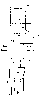
FIGURE 1 depicts a three phase electrical power system
employed to power downhole equipment according to one
embodiment of the present invention;
FIGURES 2A-2B illustrate in greater detail circuit
diagrams for sine wave filters employed within a three
phase electrical power system for downhole equipment
according to one embodiment of the present invention; and
FIGURE 3 depicts a plot of gain versus frequency for a
sine wave filter employed within a three phase electrical
power system according to one embodiment of the present
invention.
7
CA 02408795 2002-11-12
WO 01/89068 PCT/USO1/15249
DETAILED DESCRIPTION OF THE INVENTION
FIGURES 1 through 3, discussed below, and the various
embodiment used to describe the principles of the present
invention in this patent document are by way of
illustration only and should not be construed in any way to
limit the scope of the invention. Those skilled in the art
will understand that the principles of the present
invention may be implemented in any suitably arranged
device.
FTGURE 1 depicts a three phase electrical power system
employed to power downhole equipment according to one
embodiment of the present invention. The electrical power
system 102 located at the surface o-f a borehole is coupled
to a motor and pump 104 adapted for use within a borehole
and disposed within the borehole by connection to tubing
lowered witr~r~ the well casing. Motor and pump assembly
104 includes an electrical submersible pump (ESP) in the
exemplary embodiment, which may be of the type disclosed in
U.S. Patent No. 5,845,709, coupled to an induction motor.
The induction motor drives the ESP and is powered by three
phase power transmitted over three phase transmission cable
8
CA 02408795 2002-11-12
WO 01/89068 PCT/USO1/15249
106 electrically coupling motor and pump assembly 104 to a
surface power system including generator 108 and drive 110.
Three phase transmission cable 106 include separate
conductors for each electrical power phase and transmits
power from the surface power system including generator
108, which produces three phase power, coupled to variable
frequency drive (VFD) 110, designed to provide the
appropriate voltage waveform at a selected frequency within
a defined operating frequency range for powering motor and
pump assembly 104. In the exemplary embodiment variable
frequency drive 110 is a pulse width modulated (PWM) drive
operationally regulated by a controller 112. Controller
112 for drive 110 changes the output frequency of drive 110
by altering the width of pulses forming the output voltage
in accordance with the known art. Other suitable existing
power electronics inverters may be employed for drive 110.
In the present invention, drive 110 may have a maximum
output voltage (anywhere within the operating frequency
range) which is lower than a voltage required for powering
motor and pump assembly 104 disposed within the borehole.
Drive 110 may be a low voltage drive having a maximum
output voltage of only 480 volts (V), for example, while
motor and pump assembly 104 may include a medium voltage
9
CA 02408795 2002-11-12
WO 01/89068 PCT/USO1/15249
motor requiring 1,000 V to 4,000 V at the surface.
(Surface voltages are referenced since the cable 106, which
may be thousands of feet long, will cause significant
attenuation between the surface voltage and the voltage at
the motor downhole.) Alternatively, drive 110 may have a
maximum output voltage of 4,160 V, while a surface voltage
of 5,000 V is requires to power motor and pump assembly
104. To boost the output voltage of drive 110, a sine wave
filter 114 is coupled within the three phase power system
102 between the output of drive 110 and three phase cable
106 carrying power into the borehole.
While the sine wave filter 114 is preferably located
at the surface, alternatively the sine wave filter may
located downhole proximate to the motor, in which case the
parameters of interest are the received input voltage at
the input of the sine wave filter 114 received from the
surface and the required motor voltage.
FIGURES 2A and 2B illustrate in greater detail circuit
diagrams for sine wave filters employed within a three
phase electrical power system for downhole equipment
according to one embodiment of the present invention. Sine
wave filter 114a depicted in FIGURE 2A includes three
inductors LA, LB, and Z~ each serially connected within a
CA 02408795 2002-11-12
WO 01/89068 PCT/USO1/15249
phase A, B and C, respectively, of the three phase pcwer
system between the output of the variable frequency drive
and the three phase power cable 106 transmitting the power
downhole. Sine wave filter 114a also includes three dell a-
connected capacitors CAB, CB~, aid CAS between phases A and
B, between phases B and C, and between phases A and C,
respectively, of the three phase power system.
Sine wave filter 114a depicted in FIGURE 2B also
includes three inductors LA, LB, and L~ each serially
connected within a phase A, B and C, respectively, of the
three phase power system, but contains three Y-connected
capacitors CA, CB, and C~ connected within phases A, B and C
of the three phase power system, between the respectively
phase and a common or neutral point.-
In either implementation (114a in FIGURE 2A or 114b in
FIGURE 2B), inductors LA, LB, and L~ each have the same
inductance L, and either capacitors CAB, CB~, and CAS or
capacitors C;_, CB, and C~ each have the same capacitance C
(although the capacitance C of, for example, CA is not
necessarily the same as capacitance C of CAB). The
inductance L and capacitance C are selected to provide a
filter voltage gain for three phase power at a maximum
operational frequency of the variable frequency drive which
11
CA 02408795 2002-11-12
WO 01/89068 PCT/USO1/15249
is preferably equal to the ratio of the desired voltage for
powering dowrhole equipment to the maximum output voltage
of the drive.
FIGURE 3 depicts a plot of gain versus frequency for a
sine wave filter employed within a three phase electrical
power system according to one embodiment of the present
invention. The sine wave filter 114a or 114b is tuned to
have a resonant frequency fo which is offset from (higher
than) the maximum operational frequency fmax of the variable
frequency drive. The resonant frequency of the filter may
be determined from:
1
.~o - 2~ 3LC ~ ( 1 )
The sine wave filter is also designed to have a quality
factor Q, when excited by three phase power, which is
greater than one. The quality factor Q may be determined
from:
Q _ 3(2~').foL ( 2 )
R
where R is the resistance of the sine wave filter
components. The sine wave filter quality Q represents the
gain of the filter at resonance, and thus the sine wave
filter is capable of boosting the output voltage of the
12
CA 02408795 2002-11-12
WO 01/89068 PCT/USO1/15249
variable frequency ,drive by a factor equal to--or nearly
equal to--the filter Q at the resonant frequency.
Because the drive frequency changes, however, it is
not desirable to match the resonant frequency of the sine
wave filter to the maximum operational frequency of the
variable frequency drive. The high Q required to minimize
filter losses under such circumstances would provide too
much gain at the maximum operating frequency. Also,
operating very close to the peak of the filter' s resonance
frequency would place operations on a very steep part of
the filter's gain curve (gain plotted as a function of
frequency, illustrated in FIGURE 3), making voltage
regulation difficult.
Therefore, the sine wave filter is designed to have a
resonant frequency offset from (and preferably higher than)
maximum operating frequency of the variable frequency
drive, on a portion of the frequency-dependent gain curve
for the filter which is sufficiently gradual to permit
voltage regulation (i.e., preferably within the range of
voltage variances supported by the drive).
For example, if the maximum operational frequency of
the variable frequency drive is 80 Hertz (Hz), the sine
wave filter may be tuned to have a resonant frequency
13
CA 02408795 2002-11-12
WO 01/89068 PCT/USO1/15249
within the range of 90 Hz to 200 Hz, or more likely within
the range of 90 Hz to 120 Hz. The filter is preferably
always tuned for a resonant frequency higher than the
drive's maximum operating frequency due to the need for a
positive volts-per-Hertz ratio.
Since the gain G will vary with the frequency of the
three phase power exciting the sine wave filter, the filter
is preferably designed to provide a maximum gain GmaX at the
maximum operating frequency fmaX of the drive. The maximum
gain Gmax is preferably equal to the ratio of the desired or
required (surface) voltage to the maximum output voltage of
the drive. In one of the examples described above, the
sine wave filter would be designed to have a gain at the
maximum operational frequency of the drive (e.g., 80 Hz)
equal to 5,000/4,160, or about 1.2. In embodiments in
which the filter resonant frequency is higher than 'the
maximum operating frequency of the sine wave filter, the
sine wave filter 114 will also have a minimum gain Gmin at
the minimum operational frequency fmi" of the drive. It
would be desirable, but is not necessary, for the minimum
gain Gmin to be greater than one.
The inductances and capacitances required to obtain a
desired resonant frequency fo, and/or maximum gain Gmax at
14
CA 02408795 2002-11-12
WO 01/89068 PCT/USO1/15249
the maximum operating frequency fmaX of a particular
generator/drive configuration, for the sine wave filter
114, may be determined utilizing existing electrical
simulation programs.
Referring back to FIGURE 1, when excited by the output
of drive 110 (utilizing power received from generator 108)
filter 114 will (at least partially) resonate at the output
frequency of drive 110, thus increasing the output voltage
of filter 114 over the output voltage of drive 114 by a
factor equal to the gain G of the filter 114 at the output
frequency of drive 110. By tuning filter 114 to a resonant
frequency above the maximum output frequency fmax of drive
110, the voltage boost provided by filter 114 will follow
the output frequency of drive 110. In operation of
electrical power system 102, the output voltage of filter
114 is connected by feedback loop 116 to controller 112.
Controller 112 may thus monitor and regulate the output
voltage of filter 114, altering the output voltage of
filter 114 by controlling the output voltage and/or the
output frequency of drive 110.
For a pulse width modulated variable frequency drive,
sine wave filter 114 has the additional benefit of
smoothing the voltage output of drive 110 into a very
CA 02408795 2002-11-12
WO 01/89068 PCT/USO1/15249
sinusoidal signal. For electrical submersible pumps, such
smoothing of the power signal prevent problems f__r_om
resonant frequencies and reflected waves, in addition to
boosting the output voltage of the drive 110.
Although one or more embodiments of the present
invention have been described in detail, those skilled in
the art will understand that various changes, substitutions
and alterations herein may be made without departing from
the spirit and scope of the invention it its broadest form.
16