Language selection

Search

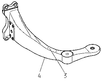
Patent 2409322 Summary

Third-party information liability

Some of the information on this Web page has been provided by external sources. The Government of Canada is not responsible for the accuracy, reliability or currency of the information supplied by external sources. Users wishing to rely upon this information should consult directly with the source of the information. Content provided by external sources is not subject to official languages, privacy and accessibility requirements.

Claims and Abstract availability

Any discrepancies in the text and image of the Claims and Abstract are due to differing posting times. Text of the Claims and Abstract are posted:

  • At the time the application is open to public inspection;
  • At the time of issue of the patent (grant).
(12) Patent Application: (11) CA 2409322
(54) English Title: OFFSET AXLE
(54) French Title: PONT PORTIQUE
Status: Deemed Abandoned and Beyond the Period of Reinstatement - Pending Response to Notice of Disregarded Communication
Bibliographic Data
(51) International Patent Classification (IPC):
  • B60G 11/28 (2006.01)
  • B60B 35/12 (2006.01)
  • B60G 09/00 (2006.01)
  • B60K 17/04 (2006.01)
(72) Inventors :
  • LENZ, PAUL (Germany)
  • JUNK, ALFRED (Germany)
(73) Owners :
  • ZF FRIEDRICHSHAFEN AG
(71) Applicants :
  • ZF FRIEDRICHSHAFEN AG (Germany)
(74) Agent: NORTON ROSE FULBRIGHT CANADA LLP/S.E.N.C.R.L., S.R.L.
(74) Associate agent:
(45) Issued:
(86) PCT Filing Date: 2001-06-02
(87) Open to Public Inspection: 2002-11-15
Availability of licence: N/A
Dedicated to the Public: N/A
(25) Language of filing: English

Patent Cooperation Treaty (PCT): Yes
(86) PCT Filing Number: PCT/EP2001/006315
(87) International Publication Number: EP2001006315
(85) National Entry: 2002-11-15

(30) Application Priority Data:
Application No. Country/Territory Date
100 28 278.4 (Germany) 2000-06-07

Abstracts

English Abstract


The offset axle for buses has a housing in which a differential is located,
said differential being connected to two axle shafts; and a suspension for
connecting the housing to the vehicle. Said suspension has single or multiple
part spring carriers which consist of corelessly, completely cast metal. Humps
can be provided in the area of the curvature between the spring element and
the housing in order to increase strength.


French Abstract

Le pont portique d'autocars présente, d'une part, un carter qui abrite un différentiel, lequel est relié à deux arbres d'essieu et, d'autre part, une suspension permettant de relier le carter au véhicule et présentant des supports de ressorts constitués d'une ou de deux pièce(s). Les supports de ressorts sont des pièces moulées pleines sans noyau. Dans la zone de courbure entre l'élément ressort et le carter, la résistance mécanique peut bénéficier de bosses rehaussées.

Claims

Note: Claims are shown in the official language in which they were submitted.

4
Claims
1. Offset axle for motor vehicles, in particular for buses, with a housing
accommodating a
differential, which is linked to two axle shafts and to a suspension system
linking the housing
to the vehicle, whereby the suspension system features single- or multi-part
spring carriers,
which are mounted to the housing and via spring and / or damping elements to
the vehicle,
characterized
in that the spring carriers consist of core-less, full-cast metal.
2, Offset axle according to Claim 1,
characterized
in that raised humps (4) increasing strength are provided in the area of the
bend (3) between
spring element and housing.
3. Offset axle according to Claims 1 and 2,
characterized
in that the spring carriers are bent towards the vehicle underside.
4. Offset axle according to one of the preceding claims,
characterized
is that the spring carrier is nearly straight in the area between its link to
the housing and its
first support, which is preferably for a spring element.

Description

Note: Descriptions are shown in the official language in which they were submitted.


CA 02409322 2002-11-15
The following invemion conoems an offxt axle for motor vebncles, espocially
buses, with a
housing accommodating a ditial linked to two axle shafla and with s suspension
system
linking the housing with the vehicle, according to the nomen collectivum of
Claim 1.
Offset axles for buses have been known for a long time. Their putpoec is to
allow the loading
surface or floor height between the driven wheels to be as low as possible. DE
A 22 56121
describes as axle arrangement for buses is which by means of universal shags
the did
of the bus axle is situated at a lower level than the actual final drive
shafts. This allows the
wheels to have separate reduction gears.
As city buses are co1>sidend optimal if their d-gage uadacauiage permits lull
width of
the aisle also between the whoels and as aisle level for the entice length of
the bus at a height
above the ground permitting single-step entry from the sidewalk, DE 3027806
proposes a
drive aide with a countershaft arranged between the spur gear countershaft
transmissions on
either side at a distancx below the final drive sbafts taattamoum to the
offset distance; with the
drive shaft essentially consisting of a co~mtershaR 6ransrnissiot~, which is ~
in an
offset aide housing, and linlang the two spur gear couatdrshaft
trxnsmissioa~s, which are
arranged in the immediate vicinity of the wheels, and co~nsiSting of a bevel
scar drive with
diffenatietl, whose output bevel gear is aonrotationally connected to the
countershaft and
whose input bowel gear is linkod to the transmission or the drive motor of the
bus via a cardaa
shaft. The two spur gear countershaft transmissions form a twin-countershaft
t~smission
with power distribution via two intermediate gears constantly meshing with the
output gear,
with one of the spur gear countershaft transmissions being housed in a single
housing tpget~her
with the bevel gear and the differential, and with both housings having
mounting points for
Chassis support. Frutllermore, both housings are linked to cash other by an
axle housing,
whose height is lowest in the vehicle ce~er and in which an unsplit plug-in
shaft is installed
as the longer part of the countershaft.
This permits favorable reduction sts~s, bar smoothes and tbimter gear wheels,
whereby
the offxt distance roquircd for an optimum try level can be achievod with
lhrll aisle width
EP B 599 293 describes a driven axle arrange for vehicles; with a central
housing having
mounting el~ents linidag the central housing to the vehicle; with a main
driver arranged in
the central housing and featuring a di$~tial gear unit; with lateral drives
arranged at the
rnrter ends of the central housing: with wheel hub units, each linked to the
lateral drives,
vvhemby an offset distance is provided between a ce~ct axis, a di$erential
gear unit arranged
in the central housing and a longitudinal axis of the wheel hub units, whereby
the suspension
clemetrts Iiabng the central housing to the vehicle are mounted in an
integrrated manner to
housings of the lateral drives, and whereby the housings of the lateral
drives, the central
housing and the suspension elf form a compact unit; with suspcnsiam elements
featuring
essentially C-shapod arms as woll as linking poirns for mounting the axle
arrangemem to the
vehicle.
Tlx pension eltmcats and the housings of the lateral drives of this ogset axle
are single-
piece units, wltcreby the essentially C-shaped arms are made of a cloxd pmSle,
with tla3 ends
of the arms flatter away from the ce~al housing featZUing air springs and
shock absorbers as
damping elentents.

CA 02409322 2002-11-15
2
DE 196 04 X30 of the applicant describes au ofl'Set axle for low floor city
buses, with a
diffareatial fir, of which each aide shaft is plugged into a drive pinion of a
portal
ttaasmias~ion with reduction elect, w ith the di$tc~e~ial gear being ansagbd
freely floating
and self-centering between two inteme pinions, with each intenmadiate pinion
transmitting half the input power via a spur gear to the wheel drive, whereby
the axle shafts
arc lower than the wheel axles by a distance equivalent to the offset
d;stance, due to the two
portal drives. In order to be able to integrate disJc brakes in the offset
axle system without
reducing aisle widdt. in the area of the axle, and to obtain a low floor level
with reduced portal
depth, the axle shafts arc arranged off-center ax the upper edge of the inner
space of the axle
bridge housing.
These offset axles have in common that the oao-pieoe or mufti piece spring
carriers are made
as cast components with an ina,er core and core support. These spring carriers
or spring carrier
halves are relatively bulky because of the inner carp. Due to dye core
supports, these spring
carriers are win the critical sations. Casting technology does not permit the
core
supports to be omitted. Due to their bulkiness, these spring carriers are
relatively heavy.
It is the purpox of the ptestnt invention to design the spring carriers or
spring carrier halves
for oiI'set axles of aRpeclally buses in such s manner that on the one hand
weight is saved and
on the other hand it is possible to reduce production costs.
Starting from an offset axle of the kind described above, the task is solved
by means of the
feature described in the distinctive part of Claim 1; favorable arraagemems
are desetibed in
tire sub-claims.
The invention provides for spring carriers made of coro-less full-cast metal.
As a
consequence, the inner care and the core supports can be omitted.
As a rule, the area of critical is at the bend between air spaing and portal
housing. In
this area, the invention provides for roop or bottom humps to stabili~c the
spring carrier.
The spring carrier as p~covidod for by the invention permits weight savings of
about 20'Yo per
carrier or par carrier part. The cost reduction is due to omission of iraxr
core and core
supports. At the same time, surface inertia is improved.
The spring carrier as invented is optimally designed if its uppex Suction,
i.e. facing the vehicle
uadetaide, is bent
In the area betv~roen the ia~r~oe with the spur gear oountar's6aft fission and
the fast
scat, e.g. fnr the air spring, it is advaamgeous if spring carrier design is
as straight as possible.
Of course, this is only possible within the limits allowed by wheel clearance.
In the following, the invention is described in more de~teil an the basis of
the drawings
Fig. 1 a pacspoctive view of a traditional spring carrier
Fig. 2 a perspective view of a spring carrier as inventiod hare
Fig. 3 various perspective views of spring carriers
Fig. 8 a pcrspecxivc view of a single-piece spring carrier for a coach

CA 02409322 2002-11-15
3
Offset axles for motor vehicles and buses are well known to the racpert,
therefore the
illusaati~s show only the es~tiat parts needed to understand tho invention.
Usually, offset
axles have a liaasing acconsmodating a diff~tial, which is linked to two axle
shags, and a
suspension system to link the housing with the vehicle, with the suspension
having single- o~r
multipart spring catriecs, which are mounted to the housing on the one head
and via damping
or spring elements to the vehicle on the other hand.
One part of a two part spring carrier is shown in pcrspedive in Fig. l, with
this conventional
spring carrier featuring an itmer core (not shown in the drawing) sad two core
supports 1, 2.
Such a spring carrier is bulky because of the inner corn. Due to the core
supports l, 2, the
caaicr is also weakened in its critical sectivas. Casting technology does not
permit these core
supports to be omitted. Due to its design, such a spciag carrier is relatively
heavy.
Fig. 2 shows a perspective view of a rose-less, full-cast sprung carrier a~ag
to the present
invention. The inner come with its core supports has boon oatitted. As a rule,
the bent arcs 3
between the air spring and the portal housing is critical is production. In
this area, either top
or bottota humps 4 are arranged to stabilize the component. In Fig. 2, the
hump is on the
underside.
Fig. 3 shows a perspective side view and Fig. 4 a perspective top view of the
spring carrier
according to the invention. Fig. S shows a front view and Fig. 6 a pardal
caraway side view.
Fig. 7 is a ropmese~atiam similar to Fig. 2.1 ig. 8 shows a singlo-piecx
spzing carrier according
to the invention, i.e. as core-less full-cast component without inner core and
core supports,
which is particularly suited for coaches.
As alrardy me~iorard, a care-loss lull-cast spring cattier for offset axles
for buses permits
weight savings amounting to ca. 20'ye per carrier, whereby omission of inner
core and core
supports allows ch~per production. At the same time, siaface inesda is
improved.

Representative Drawing
A single figure which represents the drawing illustrating the invention.
Administrative Status

2024-08-01:As part of the Next Generation Patents (NGP) transition, the Canadian Patents Database (CPD) now contains a more detailed Event History, which replicates the Event Log of our new back-office solution.

Please note that "Inactive:" events refers to events no longer in use in our new back-office solution.

For a clearer understanding of the status of the application/patent presented on this page, the site Disclaimer , as well as the definitions for Patent , Event History , Maintenance Fee  and Payment History  should be consulted.

Event History

Description Date
Application Not Reinstated by Deadline 2006-06-02
Time Limit for Reversal Expired 2006-06-02
Deemed Abandoned - Failure to Respond to Maintenance Fee Notice 2005-06-02
Letter Sent 2003-07-28
Inactive: Single transfer 2003-06-06
Inactive: Courtesy letter - Evidence 2003-02-18
Inactive: Cover page published 2003-02-13
Inactive: Notice - National entry - No RFE 2003-02-11
Application Received - PCT 2002-12-10
National Entry Requirements Determined Compliant 2002-11-15
Application Published (Open to Public Inspection) 2002-11-15
National Entry Requirements Determined Compliant 2002-11-15

Abandonment History

Abandonment Date Reason Reinstatement Date
2005-06-02

Maintenance Fee

The last payment was received on 2004-05-20

Note : If the full payment has not been received on or before the date indicated, a further fee may be required which may be one of the following

  • the reinstatement fee;
  • the late payment fee; or
  • additional fee to reverse deemed expiry.

Patent fees are adjusted on the 1st of January every year. The amounts above are the current amounts if received by December 31 of the current year.
Please refer to the CIPO Patent Fees web page to see all current fee amounts.

Fee History

Fee Type Anniversary Year Due Date Paid Date
Basic national fee - standard 2002-11-15
MF (application, 2nd anniv.) - standard 02 2003-06-02 2002-11-15
Registration of a document 2003-06-06
MF (application, 3rd anniv.) - standard 03 2004-06-02 2004-05-20
Owners on Record

Note: Records showing the ownership history in alphabetical order.

Current Owners on Record
ZF FRIEDRICHSHAFEN AG
Past Owners on Record
ALFRED JUNK
PAUL LENZ
Past Owners that do not appear in the "Owners on Record" listing will appear in other documentation within the application.
Documents

To view selected files, please enter reCAPTCHA code :


To view images, click a link in the Document Description column. To download the documents, select one or more checkboxes in the first column and then click the "Download Selected in PDF format (Zip Archive)" or the "Download Selected as Single PDF" button.

List of published and non-published patent-specific documents on the CPD .

If you have any difficulty accessing content, you can call the Client Service Centre at 1-866-997-1936 or send them an e-mail at CIPO Client Service Centre.


Document
Description 
Date
(yyyy-mm-dd) 
Number of pages   Size of Image (KB) 
Description 2002-11-14 3 202
Drawings 2002-11-14 5 48
Representative drawing 2002-11-14 1 5
Abstract 2002-11-14 1 54
Claims 2002-11-14 1 25
Notice of National Entry 2003-02-10 1 189
Courtesy - Certificate of registration (related document(s)) 2003-07-27 1 106
Courtesy - Abandonment Letter (Maintenance Fee) 2005-07-27 1 175
Reminder - Request for Examination 2006-02-05 1 117
PCT 2002-11-14 12 468
Correspondence 2003-02-11 1 24