Language selection

Search

Patent 2409385 Summary

Third-party information liability

Some of the information on this Web page has been provided by external sources. The Government of Canada is not responsible for the accuracy, reliability or currency of the information supplied by external sources. Users wishing to rely upon this information should consult directly with the source of the information. Content provided by external sources is not subject to official languages, privacy and accessibility requirements.

Claims and Abstract availability

Any discrepancies in the text and image of the Claims and Abstract are due to differing posting times. Text of the Claims and Abstract are posted:

  • At the time the application is open to public inspection;
  • At the time of issue of the patent (grant).
(12) Patent: (11) CA 2409385
(54) English Title: SEPARABLE, FLEXIBLE ELECTRICAL CONNECTION ARRANGEMENT
(54) French Title: SYSTEME DE CONNEXIONS ELECTRIQUES SEPARABLES ET SOUPLES
Status: Term Expired - Post Grant Beyond Limit
Bibliographic Data
(51) International Patent Classification (IPC):
  • H01R 13/44 (2006.01)
  • H01R 13/73 (2006.01)
(72) Inventors :
  • TERHUNE, DANIEL M. (United States of America)
  • POTTER, DAVID E. (United States of America)
  • SWANSON, ROY T. (United States of America)
(73) Owners :
  • S&C ELECTRIC COMPANY
(71) Applicants :
  • S&C ELECTRIC COMPANY (United States of America)
(74) Agent: OSLER, HOSKIN & HARCOURT LLP
(74) Associate agent:
(45) Issued: 2010-01-12
(22) Filed Date: 2002-10-23
(41) Open to Public Inspection: 2004-04-11
Examination requested: 2007-09-05
Availability of licence: N/A
Dedicated to the Public: N/A
(25) Language of filing: English

Patent Cooperation Treaty (PCT): No

(30) Application Priority Data:
Application No. Country/Territory Date
60/418,083 (United States of America) 2002-10-11

Abstracts

English Abstract

A separable, flexible connection arrangement is provided for connection of two conductors. In one arrangement, the separable, flexible connection arrangement is utilized to provide an externally removable bushing for connecting an electrical component located within a sealed enclosure.


French Abstract

Un système de connexions séparables et souples est prévu pour la connexion de deux conducteurs. Dans un mode de réalisation, le système de connexions séparables et souples sert de douille extérieurement amovible pour connecter un composant électrique situé à l'intérieur d'une enceinte étanche.

Claims

Note: Claims are shown in the official language in which they were submitted.

The embodiments of the invention in which an exclusive property or privilege
is
claimed are defined as follows:
1. An electrical connection arrangement for providing interconnection
between a first conductor and a second conductor, the arrangement comprising:
an externally removable, separable bushing connector for providing an
electrical connection through a wall comprising an insulating portion, a first
conductor
extending through said insulating portion, means for fastening said insulating
portion
to the wall; and connection means carried by said first conductor;
a switch blade member including a generally circular contact portion defining
said second conductor; and
a shaft carrying said switch blade member, said connection means comprising
first contact portions for providing electrical connection to said second
conductor and
interfitting about said shaft, whereby connection is effected via relative
movement
between said first and second conductors.
2. The electrical connection arrangement of claim 1 wherein said
connection means comprises flexible connection means for relative movement
between said first and second conductors when connected.
3. The electrical connection arrangement of claim 1 wherein said first
contact portions comprise two spaced plates each having a yoke-shaped opening,
the two spaced plates engaging said circular contact portion on opposite sides
thereof.
-5-

Description

Note: Descriptions are shown in the official language in which they were submitted.


CA 02409385 2002-10-23
SEPARABLE, FLEXIBLE ELECTRICAL CONNECTION ARRANGEMENT
BACKGROUND OF THE INVENTION
I=field of the Invention
The present invention relates generally to flexible connections and more
particularly to an externally removable bushing that provides a flexible
connection to
components located within a switchgear.
Description of the Related Art
Switchgear for electrical power distribution systems commonly include
enclosures defining contained environment desirable for circuit-interrupting
functions
of the enclosed components. In order to connect the enclosed components to
external power cables, a bushing is utilized to provide a conductor through
the
sealed enclosure of the switchgear and to insulate the conductor from the
enclosure.
The bushing typically includes provisions for assembly with separable
connectors
which interface between the bushing and the power cables. The external
portions of
l:he bushing are subject to damage which may render the bushing unusable,
requiring replacement of the bushing. This requires disconnection of the
bushing
from the enclosed components. If this disconnection of the bushing requires
opening
of the enclosure, the replacement of the bushing is not only time-consuming
and
difficult to perform in confined spaces, the design of the switchgear
enclosure is also
complicated thereby since opening features must be incorporated.
U.S. Patent Nos. 4,767,351 and 5,904,577 illustrate arrangements that
provide an externally-separable bushing such that connection and disconnection
to
enclosed components may be accomplished external to the enclosure and not
requiring opening of the enclosure. in 4,767,351, the conductor of that
bushing
arrangement includes a cylindrical rod which is permanently and rigidly
attached to
the enclosed component and a sleeve with annular passage that receives the
rod.
The bushing also includes provisions for threadably connecting the two
conductor
parts. Thus, the bushing is removed by unthreading of the bushing from the
cylindrical conductor such that the remainder of the bushing may be removed.
This

CA 02409385 2002-10-23
arrangement also requires provisions for sealing the junction of the two
conductor
parts.
While the prior art arrangements may be useful to provide connections to
Enclosed electrical components, it is always desirable to provide simplified
rnanufacture and structure.
SUMMARY OF THE INVENTION
Accordingly, it is a principal object of the present invention to provide an
externally removable bushing connector that provides connection to an
electrical
component located within a switchgear enclosure while providing ease of use
and a
flexible connection to the electrical component.
These and other objects of the present invention are efficiently achieved by
the provision of a separable, flexible connection arrangement for two
conductors. !n
one arrangement, the separable, flexible connection arrangement is utilized to
IS provide an externally removable bushing for connecting an electrical
component
located within a sealed enclosure.
BRIEF DESCRIPTION OF THE DRAWING
The invention, both as to its organization and method of operation, together
with further objects and advantages thereof, will best be understood by
reference to
the specification taken in conjunction with the accompanying drawing in which:
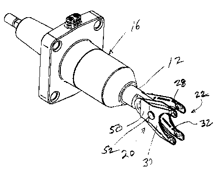
FIG. 1 is a perspective view of the connection arrangement of the present
invention;
FIG. 2 is a top plan view of FIG. 1 and including a switch blade assembly;
FIG. 3 is a partial, sectional view taken generally from the line 3-3 of FIG.
2;
FIG. 4 is a perspective view of a switch blade assembly to which connection is
made by the present invention; and
FIGS. 5 and 6 are respective front and right-side elevational views of a
contact
plate of the connection arrangement of the present invention.
DETAILED DESCRIPTION
Referring now to FIGS. 1-6, the connection arrangement 10 of the present
invention provides a separable, flexible electrical connection between two
conductors
12, 14. In a specific illustration as shown in FIGS. 1 and 2, the conductor 12
of the
-2-

CA 02409385 2002-10-23
connection arrangement 10 is the conductor of a bushing 16 that is externally
removable with respect to a wall 18 of an enclosure 19 (FIG. 2). The conductor
14
provides electrical connection to an electrical component (not shown) housed
in the
Enclosure 19. The bushing 16 is removable from the wall 18 via a fastening
arrangement, e.g. fasteners 15 that are carried by the wall 18 and pass
through
apertures 17 in the bushing 16. Thus, when the bushing 16 is unfastened from
the
uvall 18, the bushing 16 may be disconnected from the conductor 14 and removed
for
replacement etc. The connection arrangement 10 is movable along the direction
60
for connection to and disconnection from the conductor 14.
The connection arrangement 10 includes a contact arrangement 20 that
makes electrical connection with the conductor 12 and includes a separable
contact
2 2 that is arranged for separable connection with the conductor 14. In the
illustrative
f:xample, the conductor 14 is a central hub portion of an overall switch blade
assembly 24 that is carried on and rotates with an operating strut or shaft 26
about
an axis 27 (FIG. 4). The separable contact 22. includes two parallel, opposed
contact
plates 28, 30 each of which including a y-shaped or yoke contact opening 32
along
the leading edge thereof. The contact openings 32 intefit about the operating
strut
26 while the plates 28, 30 engage the hub of the conductor 14 to provide the
electrical connection thereof. As shown in FIG. 3, contact is made between the
conductor 14 and the plates 28, 30 at protruding contact portions 34, 36
respectively
provided at the upper and lower portions of the yoke contacts. In a preferred
embodiment, the contact portions 34, 36 are elongated and tapered along an
axial
direction 60 of the bushing 16 while being generally curved in the direction
transverse thereto as show in FIG. 6. The contact arrangement 20 includes
generally spherical contact portions 40, 42 on the plates 28, 30 respectively
to
provide electrical connection with the conductor 12 at 43 via a slotted
portion 44 of
the conductor 12 and a rivet 46 that passes through apertures 41 in the
spherical
contact portions 40, 42. The contact arrangement 20 also includes two spring
members 48, 50 disposed on the outside of the plates 28, 30 respectively and a
rivet
52 that passes through apertures 54 in the plates 28, 30 and apertures 56 in
the
spring members 48, 50. The spring members are arranged to compress the spring
members 48, 50 so as to provide a desired contact force, e.g. approximately 50
pounds. A spacer element 57 is provided about the rivet 52 and between the
contact plates 28, 30. Thus, the contact arrangement 20 is movable for
rotation
about the rivet 46.
-3-

CA 02409385 2002-10-23
In accordance with important aspects of the present invention, the connection
arrangement 10 provides a stable connection arrangement with resilient and
flexible
characteristics to accommodate positional changes between the conductors 12
and
14 while maintaining desired electrical connection and contact pressure, and
also
permits the bushing 16 to be removed from the housing 19 without entering the
interior of the enclosure 19 which is gas-filled in an illustrative
embodiment. For
example, the connection arrangement 10 prevents rotation of the contact plates
28,
30 away from the switch blade assembly 24 in the direction 58 via the
engagement
of the yoke portions around the operating strut 26. Furthermore, the
connection
arrangement 10 is prevented from sliding away from the switch blade assembly
24 in
the direction 60 via the mounting of the bushing 16 and the limited movement
of the
contact arrangement 20 in the direction 60. Thus, the connection arrangement
10
provides separable, but definite orientation and stability.
While there have been illustrated and described various embodiments of the
present invention, it will be apparent that various changes and modifications
will
occur to those skilled in the art. Accordingly, it is intended in the appended
claims to
cover all such changes and modifications that fall within the true spirit and
scope of
the present invention.
-4-

Representative Drawing
A single figure which represents the drawing illustrating the invention.
Administrative Status

2024-08-01:As part of the Next Generation Patents (NGP) transition, the Canadian Patents Database (CPD) now contains a more detailed Event History, which replicates the Event Log of our new back-office solution.

Please note that "Inactive:" events refers to events no longer in use in our new back-office solution.

For a clearer understanding of the status of the application/patent presented on this page, the site Disclaimer , as well as the definitions for Patent , Event History , Maintenance Fee  and Payment History  should be consulted.

Event History

Description Date
Inactive: Expired (new Act pat) 2022-10-24
Common Representative Appointed 2019-10-30
Inactive: Office letter 2010-10-06
Grant by Issuance 2010-01-12
Inactive: Cover page published 2010-01-11
Inactive: Final fee received 2009-10-16
Pre-grant 2009-10-16
Letter Sent 2009-06-02
Notice of Allowance is Issued 2009-06-02
Inactive: Approved for allowance (AFA) 2009-05-28
Inactive: Office letter 2008-02-05
Correct Applicant Requirements Determined Compliant 2008-02-04
Inactive: Office letter 2008-02-04
Letter Sent 2007-10-02
All Requirements for Examination Determined Compliant 2007-09-05
Request for Examination Received 2007-09-05
Request for Examination Requirements Determined Compliant 2007-09-05
Correct Applicant Request Received 2007-07-30
Inactive: Cover page published 2004-04-11
Application Published (Open to Public Inspection) 2004-04-11
Letter Sent 2004-02-06
Inactive: Single transfer 2004-01-16
Inactive: Office letter 2003-08-26
Request for Priority Received 2003-06-17
Inactive: IPC assigned 2003-01-28
Inactive: First IPC assigned 2003-01-28
Inactive: IPC assigned 2003-01-28
Inactive: IPC removed 2003-01-28
Inactive: Courtesy letter - Evidence 2002-12-17
Inactive: Filing certificate - No RFE (English) 2002-12-10
Filing Requirements Determined Compliant 2002-12-10
Application Received - Regular National 2002-12-10

Abandonment History

There is no abandonment history.

Maintenance Fee

The last payment was received on 2009-10-22

Note : If the full payment has not been received on or before the date indicated, a further fee may be required which may be one of the following

  • the reinstatement fee;
  • the late payment fee; or
  • additional fee to reverse deemed expiry.

Please refer to the CIPO Patent Fees web page to see all current fee amounts.

Owners on Record

Note: Records showing the ownership history in alphabetical order.

Current Owners on Record
S&C ELECTRIC COMPANY
Past Owners on Record
DANIEL M. TERHUNE
DAVID E. POTTER
ROY T. SWANSON
Past Owners that do not appear in the "Owners on Record" listing will appear in other documentation within the application.
Documents

To view selected files, please enter reCAPTCHA code :


To view images, click a link in the Document Description column. To download the documents, select one or more checkboxes in the first column and then click the "Download Selected in PDF format (Zip Archive)" or the "Download Selected as Single PDF" button.

List of published and non-published patent-specific documents on the CPD .

If you have any difficulty accessing content, you can call the Client Service Centre at 1-866-997-1936 or send them an e-mail at CIPO Client Service Centre.


Document
Description 
Date
(yyyy-mm-dd) 
Number of pages   Size of Image (KB) 
Description 2002-10-23 4 213
Drawings 2002-10-23 2 59
Abstract 2002-10-23 1 10
Claims 2002-10-23 1 38
Representative drawing 2003-02-06 1 11
Cover Page 2004-03-16 1 34
Representative drawing 2009-12-15 1 12
Cover Page 2009-12-15 1 36
Filing Certificate (English) 2002-12-10 1 159
Request for evidence or missing transfer 2003-10-27 1 102
Courtesy - Certificate of registration (related document(s)) 2004-02-06 1 107
Reminder of maintenance fee due 2004-06-25 1 111
Reminder - Request for Examination 2007-06-27 1 118
Courtesy - Certificate of registration (related document(s)) 2004-02-06 1 108
Acknowledgement of Request for Examination 2007-10-02 1 189
Commissioner's Notice - Application Found Allowable 2009-06-02 1 162
Correspondence 2002-12-10 1 24
Correspondence 2003-06-17 2 72
Correspondence 2003-08-20 1 11
Fees 2004-10-25 1 37
Fees 2005-10-24 1 32
Fees 2006-10-23 1 42
Correspondence 2007-07-30 1 37
Fees 2007-10-23 1 42
Correspondence 2008-02-05 1 14
Fees 2008-10-23 1 41
Correspondence 2009-10-16 1 42
Fees 2009-10-22 1 42
Fees 2010-09-13 1 42
Correspondence 2010-10-06 1 22