Note: Descriptions are shown in the official language in which they were submitted.
CA 02409547 2002-11-08
WO 01/86229 PCT/USO1/14881
TRANSPONDER LANDING SYSTEM
Cross-Reference to Related Application
This application claims priority under 35 U.S.C. section 119(e)
from U.S. Provisional Application Number 60/203,039 filed on May 9, 2000
and U.S. Patent Application No. 09!695,359 filed on October 24, 2000.
Background of the Invention
The present application relates to navigation systems. The invention
finds particular application in aircraft landing systems which provide
precision
elevation guidance to a user, such as a controller or pilot during approach
and
landing.
s Various precision aircraft landing systems have been employed to
assist a pilot in maintaining a desired glide path to a runway. The Instrument
Landing System (ILS) is commonly used for precision approaches; however,
ILS systems are prone to interterence from nearby FM broadcasts, require
extensive terrain grading and property acquisition at some airport sites and
to are vulnerable to guidance beam distortion when considering construction
near an airport. The Microwave Landing System (MLS) is much less
commonly employed than ILS, and is being phased out in response to
economic concerns. Precision Approach Radar (PAR) are commonly used in
military environments and require a ground operator to verbally convey glide
is path guidance corrections to the pilot via a communications link. Global
Positioning System based landing aids have been proposed which include
two systems under development, the Wide Area Augmentation System
(WARS) and the Local Area Augmentation System (LAAS) both of which are
CA 02409547 2002-11-08
WO 01/86229 PCT/USO1/14881
subject to jamming and spoofing, and may not be suitable for sole means
precision approach.
Aircraft navigation systems which employ the Air Traffic Control Radar
Beacon System (ATCRBS) transponder are generally known in the art.
s Transponders are typically deployed on aircraft to facilitate the Secondary
Surveillance Radar (SSR) function of monitoring and controlling enroute
aircraft. Most commercial aircraft are equipped with two transponder
antennas, one on the top and another on the bottom of the aircraft's fuselage
to maintain reliable transponder replies during aircraft turns. Such
transponder
to antenna configurations are known as diversity antennas. A transponder
equipped with diversity antennas selects the antenna which received the
highest amplitude interrogation signal from a ground station to transmit the
coded reply message. International Standards and Recommended Practices
presently require that the horizontal distance between the top and the bottom
is antennas be less than 7.6 meters, in order to control the apparent SSR
range
fitter from reply to reply due to antenna diversity switching. The vertical
separation of diversity antennas varies as a function of aircraft fuselage
height
and can be approximately between 3 and 10 meters.
Landing systems which use the ATCRBS transponder must determine
2o the aircraft's position, compare it to a desired approach path, and
transmit any
required correction to the aircraft. Nehama U.S. Pat. No. 3,564,543 describes
such a system, which uses symmetry and simplified mathematics to define a
conical approach path. In general, the position determining system disclosed
in Nehama and like systems is based on transponder reply time-of arrival
2s measurements derived from the time required for the interrogation to travel
to
the transponder, for the time for transponder to respond, and the time
required for signals to travel between the landing aircraft and a plurality of
locations on the ground. From these distances, the aircraft's position is
estimated. The Nehama patent acknowledges the existence of variable
so transponder reply time which can induce substantial errors in the
navigation
solution. As a compromise, Nehama arranges the transmitter and sensors in a
substantially vertical geometric plane transverse to the length of the runway.
This arrangement projects the error in a horizontal direction along the axis
of
2
CA 02409547 2002-11-08
WO 01/86229 PCT/USO1/14881
the runway. As a side effect, this arrangement requires the use of elevated
antenna towers in the vicinity of the airport, for if all the sensors were
positioned at ground level, and thus in a horizontal plane, the calculated
altitude of the aircraft would contain substantial errors, which would be
s impermissible for a precision landing system.
Stoltz U.S. Pat. No. 5,017,930 discloses a system which advances
over Nehama by, among other things, also solving for transponder encoding
delay by employing four sensors. Unfortunately, the time of arrival
measurements used by landing systems such as that described in Nehama
~o and Stoltz are subject to significant multipath errors. These multipath
errors
are induced by terrain features along the approach path to the runway and
induce errors in the time of arrival measurements. Errant time of arrival
measurements degrade the navigational solution, and thus reduce the
accuracy of guidance signals transmitted to the aircraft.
is It is desirable for landing systems to comply with the International
Standards and Recommended Practices limit on the excursion characteristics
of the navigation on-path signal which includes bends, scalloping, roughness
and other aberrations with a two-sigma limit roughly equivalent to 3 meters at
a point 1.4 km from the glide path Point of Runway Intercept. Unfortunately,
2o diversity antenna switching, even on the smallest aircraft, can potentially
cause performance out of this window.
The present invention contemplates an improved method and
apparatus which overcomes the above referenced problems and others.
2s Summary of the Invention
In accordance with one aspect of the present invention, a method of
determining a position of an aircraft having a transponder which transmits a
reply signal in response to an interrogation signal includes first receiving
reply
signals on a plurality of antennas disposed as a vertically oriented array.
so Characteristics of the reply signal, such as differential phase, amplitude,
frequency and the like, are measured and used to estimate the aircraft
position. The differential phase is analyzed between at least two reply
signals
to determine whether respective reply signals originate from different
3
CA 02409547 2002-11-08
WO 01/86229 PCT/USO1/14881
antennas on the aircraft. In the event the reply signals are determined to
originate from diversity antennas, the estimated position is adjusted to
compensate for the distance between the respective antennas. The method
also can calculate an error between the adjusted position and a desired
s position and convey this error to a user such as a pilot, air traffic
controller, or
to cockpit displays of other aircraft.
A precision aircraft landing system determines on a real-time basis the
location of an aircraft by measuring elapsed time between interrogation and
transponder reply signal at a plurality of predetermined locations. The system
zo manages the effects of multipath and achieves accurate aircraft positioning
by
measuring the transponder reply differential phase to compute angle-of-
arrival.
The present invention has the capability to compensate for transponder
diversity antenna switching, and as a consequence of this compensation,
zs achieve an elevation estimate with the least dynamic lag.
In accordance with another aspect of the present invention, a multipath
correction is applied to the selected characteristics to compensate for
multipath errors induced in the estimated position, thereby achieving the best
possible detection and compensation for diversity antenna.
2o One advantage of the present invention resides in the ability to
precisely determine aircraft position based on a cooperative transponder reply
signal originating from an aircraft.
Another advantage of the present invention resides in the ability to
manage or cancel the effects of multipath returns of the transponder reply
2s signal.
Another advantage of the present invention resides in the ability to
accurately determine aircraft position by measuring both transponder reply
angle of arrival and time of arrival.
Still further advantages will become apparent to those of ordinary skill
so in the art upon reading and understanding the following detailed
description.
Brief Description of the Drawings
4
CA 02409547 2002-11-08
WO 01/86229 PCT/USO1/14881
The invention may take form in various components and arrangements
of components, and in various steps and arrangements of steps. The figures
are only for purposes of illustrating the preferred embodiments and are not to
be construed as limiting the invention.
s Figure 1 is a perspective drawing illustrating the elements of the
Transponder Landing System in accordance with this invention;
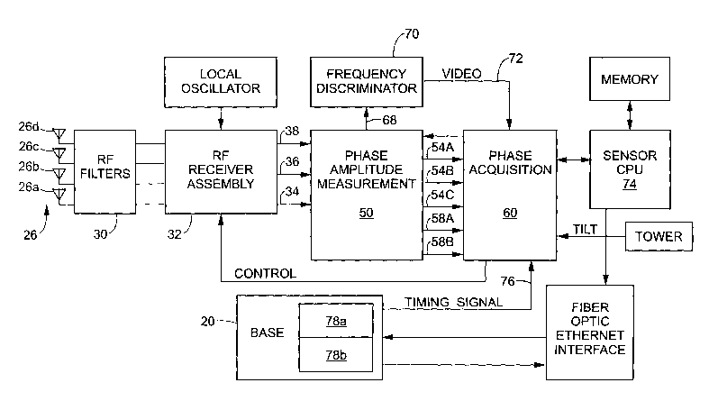
Figure 2 is a block diagram of the AOA sensor and the antenna inputs
with front-end RF assembly switching in accordance with this invention;
Figure 3 is an illustration of error attributable to diversity aircraft
to antennas;
Figure 4 is an illustration of error attributable to multipath signal
transmission; and,
Figure 5 is a flow chart illustrating processing occurring in the
processors, which suitably practices the present invention.
Detailed Description of the Invention
Referring now to Figure 1, an airport having a runway 10 is shown. A
precision aircraft landing system according to the present invention operates
to guide an aircraft along a predefined approach path (not shown), which
leads to the runway 10.
The system includes, an interrogation transmitter housed in the base
station shelter 20 that is used to generate interrogation and suppression
pulses. The interrogation signal, composed of pulses modulated onto a carrier
frequency, emanates from an interrogation antenna 22. As will be more fully
2s discussed below, a timing signal 76 is also sent from the base station 20,
coincident with the interrogation signal to receiver arrays 26, 28 to
synchronize sensor measurement processing. A transponder 86 (Figures 3,
4) on, for example an aircraft, transmits a reply signal which is also
composed
of pulses modulated onto a carrier frequency in response to receiving the
3o interrogation signal. The reply signal is received by receiver arrays 26,
28
and are forwarded, preferably to dual dissimilar processors 78a, 78b (Fig. 2)
within the base station 20 for processing. The reply signals are processed, as
s
CA 02409547 2002-11-08
WO 01/86229 PCT/USO1/14881
discussed below, for various characteristics such as time, amplitude,
frequency and differential carrier phase.
With reference now to Figure 2, a functional block diagram of
components is illustrated. Four antennas 26a-26d comprise the antenna array
s 26. For simplicity antenna array 28 is not depicted however those skilled in
the art will appreciate that similar processing will occur on signals received
on
that array. Received reply signals are received on antennas 26, pass through
filter 30 and are processed by the RF Receiver Assembly 32. By designating
one of the antennas a reference 26a and measuring differential carrier phase
to between the reference antenna 26a and one of the remaining three antennas
26b-26d, three antenna array apertures are achieved and therefore three
different resolution measurements are possible, for example low, medium and
high. The reference antenna 26a is input to a dedicated receiver path 34.
Other antennas 26b-26d are multiplexed into two RF Receiver paths 36, 38
is using switches within the RF receiver assembly 32 although those skilled in
the art can envision equivalent mechanisms to transfer signals to the
assembly. Each path 34, 36, 38 receives 1090 MHz pulse modulated RF
signals from the antennas 26 which originated from the responding
transponder. The Phase Amplitude Measurement (PAM) 50 receives the
2o intermediate frequency paths 34-38 from the RF Receiver assembly, and
provides log video signals 54, and digitized phase data 58A, 58B to the
Phase Acquisition Card (PAC) 60 for signal processing.
Two sets of digitized phase data are provided: the phase difference
between the reference and IF channel A (low, medium, or high channels 26b
2s 26d) 58A; and the difference betv~een the reference and IF channel C (low,
medium, or high channels) 58B. Log video of each of the three inputs is also
passed to the PAC 54A, 54B, 54C. A limited IF signal 68 from the low-
resolution input is provided to the Frequency Discriminator 70. The Frequency
Discriminator 70 receives the limited IF signal 68 of the RF Receiver
so assembly input, and provides an analog output 72 to the data acquisition
section of the PAC 60 for frequency measurement. The PAC 60 thus also
receives a start signal or synchronization timer coincident with the
interrogation signal via fiber optic 74 from base 20 (Fig. 1 ), log video
6
CA 02409547 2002-11-08
WO 01/86229 PCT/USO1/14881
amplitude data 54, digital phase data 58 from the PAM 50, and frequency
video 72 from the Frequency Discriminator 70. Those skilled in the art will
appreciate that the synchronization signal may be transmitted by forms of
data communication other than fiber optic cabling such as by wireless
s transmission, conventional hard wiring and the like. Alternately, the
synchronization may be implemented through internal mechanisms on the
several components such as by internal clocks or GPS signals.
Sensor acquisition begins processing RF inputs from the antennas 26
upon receipt of a start signal on cable 74. Transponder reply signals are
to analog processed and stored. Phase and frequency data is correlated with
stop video signal acquisition data. All data passes to processors 78 in the
base station 20.
Kalman filtering is used to improve the accuracy of the position
estimate. The filtering improves the accuracy by using not only the most
is recent receiver measurements, but also the previously determined position,
the statistical "reliability" of that position, and the statistical variance
of the
current measurements. The application of Kalman filtering to navigation
systems is well understood by someone skilled in the art however, the
following aspect of Kalman filter tuning is specialized to this invention. The
2o process noise covariance matrix Q is usually a heuristic set to accommodate
expected target maneuvers, but it may be set adaptively by more advanced
formulations of the Kalman filter. The process noise covariance matrix Q is an
"aging" matrix that allows acceleration events to occur in the state vector
representing the aircraft dynamics. Usually one chooses an estimated Q and
2s then "fine-tunes" ifi through computer simulation or flight test. A first
approximation for Q is usually computed by considering the maximum
acceleration that the aircraft is likely to perform. The optimal process noise
setting is achieved in conjunction with applying the Diversity Antenna (DA)
algorithm below.
3o With reference now to Figure 3 an exaggerated but exemplary
illustration of the diversity antenna error is illustrated. An aircraft 80
approaching a runway is equipped with a lower antenna 86~ and an upper
antenna 86~. As illustrated, at a first time aircraft 80 replies to an
interrogation
CA 02409547 2002-11-08
WO 01/86229 PCT/USO1/14881
with the lower antenna 86~ and the signal 90 proceeds directly to the antenna
array 26. Following the initial interrogation and reply sequence, the aircraft
has moved and is now depicted by reference number 80'. As illustrated
however, aircraft 80' because of attitude replies to a subsequent
interrogation
s with the upper antenna 86~. As discussed above, because of the separation
between the diversity antennas 86~, 86~ an error is introduced into the
navigation problem. The processors 78 in the base station 20 (Figure 2) are
equipped with a diversity antenna algorithm which evaluates the digitized
differential phase of reply signals over time to detect an aircraft
transponder
to reply originating from diversity antennas. The algorithm uses the two Angle
of
Arrival (AOA) data sets, 58A and 58B, to establish the existence of a
diversity
antenna configuration and calculate the diversity antenna separation. As
used herein, the term AOA is meant to imply any of a variety of methods to
ascertain angular offset from some predetermined normal angle of incidence,
is and includes determining an actual angular offset, determining a phase
difference between multiple signals or otherwise calculating a direction of
arrival. As more fully explained below, AOA measurements that are
determined to originate from the aircraft's upper diversity antenna are
compensated for the diversity antenna separation, to produce a measurement
2o set that would have the lower antenna as an emanation point.
In one presently preferred embodiment, the DA algorithm initializes
parameters (Table 1 ) at the start of track acquisition. These parameters are
tuned using simulation and field data by applying a wide range of aircraft
types. During an approach to a runway, detection of measurement jumps,
2s which could be due to a diversity antenna switching, is accomplished by
examining the delta between the previous and current interrogation count. If
the interrogation delta indicates sequential measurement samples, and the
range of the TOA measurement is within the maximum range 1, the sine of
the jump angle is calculated using the difference in phase from the lasfi
3o interrogation and the corresponding AOA antenna aperture, then a jump
detected flag is set to indicate that data is present. If the sine of the jump
angle is greater than the minimum 2 then the jump distance is calculated from
the jump angle (meters) and the 'direction is determined. If the jump distance
s
CA 02409547 2002-11-08
WO 01/86229 PCT/USO1/14881
is between the minimum and maximum jump limits 3,4, then jump detected
flag is set and jump amount is set to the distance. Lastly, the interrogation
count and phase measurement are stored for comparison to the next
interrogation's data. An alternate embodiment of this portion of the algorithm
s would use angle information only (2) at close range to determine when a jump
occurred.
An additional embodiment, a jump-type (Table 2) includes assigning
according to the result of the medium andlor high jumps. The confidence of a
DA configuration is calculated by weighting the number of various types of
to measurement jumps 10. High and Medium channel jumps in the same
direction have a large positive weight. In addition, the level of agreement
between the High and Medium channel jumps is used to increase the weight.
High and Medium measurement channel jumps in the opposite direction have
a large negative weight. High channel jumps when there isn't a Medium
is available (due to AOA sensor antenna interleave) have a low positive
weight.
Likewise, Medium channel jumps when there is no High channel available
have low positive weight. High or Medium channel jumps which occur when
there is a Medium or High measurement available, but that don't indicate a
jump have a low negative weight. Measurements that don't indicate any jump
2o have zero weight. A diversity configuration existence flag is set after
sufficient
number of measurement updates has satisfied the jump-set criteria 9-12
indicating that the aircraft is equipped with diversity antenna.
Once established, both a DA separation track and DA separation
variance track are estimated by two one-state Kalman filters with constant
2s gain. The tracks are calculated 5-8 based on the average of High and Medium
channel jumps in the same direction. An alternate embodiment of this portion
of the algorithm would also use individual High or Medium channel jumps
when a Medium or High, respectively, is not available, to calculate the
tracks.
The antenna status 13-27 is maintained (i.e. upper or lower diversity
3o antenna) along with the confidence in that status. A jump-type of SAME has
a
very high confidence in the direction indicated. A jump-type of OPPOSITE
sets the status to unknown. A jump-type of HIGH, MEDIUM, HIGH NOISE, or
MEDIUM NOISE has a high confidence only if the size of the jump matches
9
CA 02409547 2002-11-08
WO 01/86229 PCT/USO1/14881
the expected jump as indicated by the DA separation track, otherwise the
status confidence is reduced. A jump-type of NO DATA reduces the status
confidence. A jump-type of NONE does not change the status confidence. If
the status changes from upper to lower or vice-versa, the status confidence is
s increased. In addition, the status confidence is increased based on the
level
of agreement between the jump and the DA separation track.
A reply that is determined to be from the upper diversity antenna, is
adjusted to an emanation point that corresponds to the lower diversity
antenna, based on the DA separation track. Window thresholds 28-35 are set
to up as minimum and maximum bounds with a skew applied to the window
based on measurement track velocity 33. An adjustment is made to the
window size based on the standard deviation of the separation estimate
variance 31 and the expected measurement variance 32. A wide window,
which is a linear scaling 36 of the normal window, is also set up. The
is difference between the medium andlor high measurement and the expected
measurement is tested against these windows. The diversity antenna status
confidence 37-38 is also tested. The results of these tests 39-43 are used to
determine if the measurement should be adjusted. If so, the value of the DA
separation track is subtracted from the measurement. An alternate
Zo embodiment of this portion of the algorithm would calculate the ratio
between
the DA separation track and the difference between the expected
measurement and actual measurement. This value for the medium and/or
high measurement along with the diversity antenna status and status
confidence would be used to determine if the measurement should be
2s adjusted.
io
CA 02409547 2002-11-08
WO 01/86229 PCT/USO1/14881
Table 1: Diversity Antenna Algorithm Parameters
rameter ~ Purpose
P
a
In
accordance
wi
valuating
measurement
jumps
caused
by
diversity
antenna
switchin
1 'um eval max rn Maximum ran a to detect switchin
2 min 'um sin theta Minimum an 1e to detect switchin
3 min 'um Minimum DA switch
4 max 'um Maximum DA switch
In
accordance
with
estimatin
the
se
aration
of
diversit
antenna
se ain Filter ain for estimatin DA se aration
6 se var ain Filter ain for estimatin DA se aration
7 use medium_onlyJumps Controls use of medium only for estimating
s DA
e aration
8 use high onlyJumps Controls use of high only for estimating
s DA
eparation
In
accordance
with
determinin
diversit
antenna
existence
confidence
9 exist conf limit Limit at which DA existence is confirmed
conf weights[ Confidence weights for different
MAX JUMP SET types of
measurement 'um s
11 conf same ratio weightConfidence weight to apply towards
same
direction ratio
12 conf same ratio limitLimit for same direction ratio
In lculatin the diversit antenna status
accordance
with
ca
13 use hi h onl to a Use hi h onl 'um s to set status
er to a er
14 use medium_only_to Use medium only jumps to set status
up to upper
er
use high only to lowerUse high only jumps to set status
to lower
16 use medium only_to Use medium only jumps to set status
to to lower
war
17 both status conf Status confidence to use if both
'um
18 hi h onl status conf Status confidence to use if hi h
onl 'um
19 medium_only_status Status confidence to use if medium
con only jump
f
expectedJump_bonus Confidence bonus to apply if jump
c matches
onf ex acted
21 expected,Jump_conf Confidence limit at which an expected
limi jump
t can be determined
22 same ratio bonus confConfidence bonus for a high ratio
between
same 'um s
23 same ratio bonus limitRatio at which bonus starts to a
i
24 status_conf_reduce Amount to reduce confidence when
there are
missed detection opportunities (e.g.
Medium
on channel A & Medium on channel
C when
medium is not used to set status
n
CA 02409547 2002-11-08
WO 01/86229 PCT/USO1/14881
25 one_meas_trk ratio Ratio between a measurement jump
limit and the
D A separation track at which the
meas_trk_bonus begins to apply. This
is for
the case when there is onl one measurement
26 two meas trk ratio Ratio between a measurement jump
limit and the
D A separation track at which the
mess trk bonus begins to apply. This
is for
the case when there are two measurements
but only one indicates a jump (i.e.
Med. Noise
or Hi h Noise .
27 meas trk_bonus conf Confidence bonus to apply based on
l the ratio
b e measurement and the track
etween a sin
In
accordance
with
compensating
the
AOA
measurement
if
from
the
upper
trans
onder
antenna
28 smallest_window_min Smallest allowed window minimum
29 lar est window max Lar est allowed window maximum
30 baseline se Nominal amount to allow for DA window
31 se wei ht Wei htin factor for DA se aration
uncertaint
32 meas_trk_weight Weighting factor for measurement
track
uncertaint
33 mess vel_weight Weighting factor for measurement
track
velocit
34 a er wei ht Wei htin factor if a er antenna
35 lower_weight Weighting factor if lower antenna
36 wide window weight Weighting factor to determine slightly
wider
window
37 status hi hest conf Level at which status confidence
is hi hest
38 status hi h conf Level at which status confidence
is hi h
39 normal window is Ad'ustment oints for normal window
40 wide window is Ad'ustment oints for wide window
41 status_highest_pts Adjustment points for highest confidence
42 status hi h is Ad'ustment oints for hi h confidence
43 is limit Points re wired to ad'ust
Table 2: Jump-types and associated angle-of-arrival measurement event
Jump-type Measurement event associated with indicated
jump-type
Same High and Medium indicate a DA jump in the
same
direction.
Opposite High and Medium indicate a DA jump in the
opposite
direction.
High High indicates a DA jump and there is no
medium
available for com arison ur oses.
Medium Medium indicates a DA jump and there is
no high
available for com arison ur oses.
Hi h Noise Hi h indicates a DA 'um and medium does
not. This
12
CA 02409547 2002-11-08
WO 01/86229 PCT/USO1/14881
implies a noisy high measurement.
Medium Noise Medium indicates a DA jump and high does
not. This
im lies a nois medium measurement.
None Neither high or medium indicate a DA jump
and data
is available for at least one of them.
No Data No data is available for either hi h or
medium.
With reference now to Figure 4, an illustration of multipath returns is
provided. Signals travelling between an aircraft 80 and antennas 26a-26d
can follow two or more propagation paths between respective antennas. The
s first path is along direct line-of-sight 90 and the other paths are
reflections
from either the ground, hills, buildings vehicles, aircraft or other objects,
as a
function of the objects conductivity, size orientation and the signal angle-of-
incidence. The reflections from objects that are very close to the direct path
and allow the reflected signal to arrive very soon after the direct path
signal
to are commonly known as short-path multipath 92. Reflections from objects
further from the direct path can cause what is commonly known as long-path
multipath. Short-path multipath 92 can impact AOA measurement accuracy,
since the carrier phase of the signal that impinges on the AOA antennas is the
vector sum of the direct and multipath components. Further references to the
is short-path variety of multipath will be referred to herein as multipath 92.
Multipath errors on the reply signals are corrected by entering a
lookup table with an initial estimated aircraft position, returning with the
phase
offset calibrated to compensate for expected errors induced in each of the
low, medium, and high resolution channels as a function of aircraft position
in
2o range, azimuth, and/or elevation. Of course those skilled in the art will
appreciate that selecting various corrections from the lookup table will
require
some amount of interpolation, thresholding or other intermediate selection
techniques to determine correction values for positions in between calibrated
positions. Indeed, the transponder diversity antenna switching (as discussed
2s above) is detected more reliably with the multipath calibration correction
applied to the AOA measurements prior to employing the DA algorithm.
Recalling that multiple antennas 26a-26d are disposed together to form
an array 26 desirably provides multiple apparent apertures, thus resolutions,
13
CA 02409547 2002-11-08
WO 01/86229 PCT/USO1/14881
for analysis. Accordingly, interleaving among various channels depending on
the phase of the approach and the confidence of the position estimate is
desirable.
Initially, the antenna interleave is initially set to the low pattern per
s Table 3. The low pattern of interleave rates provide sufficient low-
resolution
measurements to establish a reliable estimate of the aircraft position. The
low-
resolution channel provides a beam width greater than that of the medium or
high channels and is used to select from the ambiguous cycles available on
the medium and high channels. An alternate embodiment of the invention
to uses the Mode C response from the transponder to resolve cycle ambiguity
for the medium and high channels, instead of using the IoW channel to resolve
cycle ambiguity. During an aircraft approach the track processing algorithm
determines the antenna interleave for subsequent interrogations based on the
position of the aircraft with respect to the desired approach path angle and
the
is desired accuracy of the aircraft position estimate, and then sets the
antenna
interleave to the low, high or approach patterns. For optimal diversity
antenna
detection and compensation the approach pattern is most desirable as it
provides the maximum opportunity to compare subsequent medium and high
channel measurements. An alternate embodiment of the antenna
2o configuration includes programmable control of a phased array to select the
apparent aperture.
Table 3: AOA Antenna Interleave Rates
"..:., .,.:::::.. : :.....:::........:...:..::..:::..:. ,.:::::
.:::::::.-:.:.::::::::::;:::.:::.:..:. : _.~:<.:::..<.::::>%,:<:::::
::::.,.,..:..::.,.,<:.-::."::::....:.,.-..;..:,.,
,:..: : ,: ;::
:. ...::.........:.;......
,::w,..~.:.:.:........ .:,rr..
t.. :.../i,u..
,.::.
..,<u:,;:. :.
i., . ,.,.~::..:::,i,:.
.., iv,.
,: ~..:.;;:t;:,;. ~ :.:.
. :.:.<s.;<:::..:..
. :~::::,;'
:. , .
a.
.r :,',.5'.
te'>.<': ~tt~r~ s.
": w': ,
~
,...I~~1 ~~
' 17L. ~
...,..:...<,~',.~<.,.::.:...a:.,,%r,.,<_:::::..~T!tt~;'~'af~~l
r
r!:., :
...'i'..i.:,r:,.i.,,y .v.:~i;.;.'.
;::;;.
vc': ::'.
:: r~.,....,,r.,,<,.:: ,~/ ~af,.
:v;>.'.:::.::a::::%:',..,i::: 4:::.~.::i%:.. .,....
./n:.:%.:v:,:-y.... .....
::;~i..,.:r::y:>i;~::::.>: ~::~::,:;:;;~%:.~ ...1:.::..
_ .. <....
. /...... .::ri
..../!... ~.,";_5':
:::://:, i..r... ,
.:.... .. ac::~..
.:: .. :.,../.. ..,..~..y.;.:://"
/ ...... .:.
:j ..::.. /
/,..:: ....:fir..,....:: ..::>.,
,..,fit,.;;i: .".
.
,. . :::::~.%/.,..,.: ,%
. "' ,.......r....
"~~%~'a.,.,.33:%.:;'.;i; ..
/. ..,..r
:....r...... .
..../ .:
a .:., :.,!
. '~'F:: .
.::::.<<.... ...,
. n,./
::<..f/;,..r,.".~.r~.l.~y:~_Y~,:Y~:5::,~ .
::~;.:~.:~'Y.::~': ..
.tf/
..: :.%' .,.
,c::. 3..~..';:3;;.,:aX'<.",.
:.. f .....,:,.
u. :~~.v....i..., ;:":%:f:~%:k.3
:;:%<:::.,.:,.
..
..:. ..":/:::%.: ,
. .. ;:;::. ..
,.................j::%: ..:;:/'
..... . .
,.: ::<: n:,:.'.~-::..:.
..:,.~/ ~.
r"!., .
... ".
:................. . ,,
:, ..
./:,:... f~/
..
.~.. , ... ..
y:''y'."i . :.. --,../:::::...:~/:,.
,:........... .... ::.,.,~
., .::.,;,',::
n........ ~.:~.::~'
,;..:.... :~
/. . '. iG~~.,
.<, ,,_..,.:.:..., ...
a ij n
. ':~Y~%i' .:
. .~~.... 'y.:~:~
L.,. ~. _ .<:.:
.:".. "f..,.... .
..i..........,. < ~~ .:~~,..,:ax..
,:.....~.,...:...',:.:.'. ,:'fi~''i:%: ,:.
,..."i ~::.'.: 6
.. l v:':..:,<:'<':'.:.~ ~
, %o,...~
,.,..... ,....,....
.....", '.:
;..:'....;,:.~~..:.:..:::,i...:::,<.::....:::::.::::.,,.:::::.:.. .
Ch. :..:."...:.:.:..;:....:::.::_:./.:.~":...
A .' ,..
Ch. Ch. A
C Ch.
C
.,...."~.
.
v'''..f
..
...i
:.:::...:.,
::..:..'..:'i~x',':'::
.
.
:
'%'%<
.......:.:.:..
/
%rai
.a
.
'
'.
,
l":...,
...
.....
.....
....
~
~
'.......
.....
..
...
~~
~r
"''
:....
i,....,:.........,..........,,..,...,..,......'%...~~i.':.:
Ch.
A
Ch.
C
1 Low Low Hi h Hi Hi Hi h
h h
2 Hi Hi h Med. Med. Med. Med.
h
3 Hi Low Hi h Med. Hi Med.
h h
4 Med. Med. Low Low Hi Med
h
Med. Low High Med. High Med.
6 Hi Low Hi h Low Hi Med.
h h
7 Hi Med. Hi h Med. Hi Med.
h h
8 Med. Low Hi h Low Hi Med.
h
9 Hi Low Hi h Med. Hi Med
h h
High Med. High Low High Med.
11 Med. Low Hi h Med. Hi Med.
h
12 Hi Low Hi h Low Hi Med.
h h
14
CA 02409547 2002-11-08
WO 01/86229 PCT/USO1/14881
13 High Med. High Med. High Med.
14 Med. Low Hi h Low Hi h Med
15 Hi Low Hi h Med. Hi h Med.
h
16 Hi Med. Hi h Low Hi h Med.
h
17 Med. Low Hi h Med. Hi h Med.
18 Hi Low Hi h Low Hi h Med.
h
19 Hi Med. Hi h Med. Hi h Med
h
20 Med. Low Hi gh Low Hi gh Med.
With reference now to Figure 5, an overview flowchart of steps which
suitably practice the present invention are illustrated. An aircraft antenna
86
s transmits a reply signal 90 which is received on a ground based antenna
array
26, as seen in step 100. The received signals are sent to processors 78 in
the base 20 to generate a position estimate from the time of arrival and the
angle of arrival of the reply signal 90, as seen in step 104. The central
processors 78 in the base 20 then perform corrections in the initial position
Io estimate to account for multipath returns of the reply signals 90, as seen
in
step 108. Following the multipath correction, the central processors 78,
running a DA algorithm employing antenna interleaving over successive
updates, determine whether the approaching aircraft 80 is responding via
diversity antennas 861, 86~ and applies a correction to the position estimate
is based on that determination, as seen in step 110.
The central processors 78 calculate a position error by comparing the
adjusted aircraft position with a desired position, such as an approach path,
as seen in step 114. Those skilled in the art can appreciate that any type of
approach path consisting of a plurality of interconnected positions which can
2o be compared against a desired aircraft position can be employed. In other
words, different from the conventional straight-in approaches now utilized at
many airport facilities, approach corridors can be defined which avoid noise-
sensitive areas, and terrain features, and/or circumnavigate areas over which
aircraft traffic is not desirable. The processors 78 convert the determined
2s position into a format usable by a user, such as an air traffic controller
or
aircraft pilot, as seen in step 918.
The invention has been described with reference to the preferred
embodiments. Obviously, modifications and alterations will occur to others
IS
CA 02409547 2002-11-08
WO 01/86229 PCT/USO1/14881
upon reading and understanding the preceding detailed description. It is
intended that the invention be construed as including all such modifications
and alterations insofar as they come within the scope of the appended claims
or the equivalent thereof.
16