Note: Descriptions are shown in the official language in which they were submitted.
CA 02409694 2002-10-31
WO 01/92645 PCT/GB01/02389
1
TITLE: PILE DRIVING
BACKGROUND OF THE INVENTION
FIELD OF THE INVENTION
The invention relates to pile driving, and more
particularly, but not exclusively, to underwater pile
driving, e.g. for stabbing piles directly into the seabed.
DESCRIPTION OF THE BACKGROUND ART
It is known to provide a guide for aligning a pile
with the surface of a substrate into which the pile is to
be driven and to provide stability for a piling hammer.
Particularly when piling underwater there is the problem
that after the pile has been introduced into the seabed or
the like, the guide must be removed to allow the pile to
be driven into its final position. This guide removal is
time consuming and thus expensive. Accordingly, the
present applicant proposed in International patent
CONFIRMATION COPY
CA 02409694 2002-10-31
WO 01/92645 PCT/GB01/02389
2
publication W099/11872 a pile guide which allows pile
driving to continue from start to finish without any need
to interrupt driving to remove the guide.
The pile driving apparatus described in W099/11872 is
supported on a base frame, a plan view of which is
reproduced in Figure 1. The base frame 10 has a
substantially rectangular footprint (made up of a welded
framework of girders and mudmats) with a centrally-placed
aperture (12) through which a pile (14) is guided. The
base frame 10 thus surrounds the pile (14) It will be
seen however, that the base frame is formed with an
aperture or slot (16) extending through the frame from its
exterior to the central aperture (12) and through which a
tether or rigging (18) fixed to the pile (14) can be
passed.
The present applicant has appreciated certain
problems associated with transporting a pile guide of the
kind shown in W099/11872. The rectangular footprint of
the base frame may have an area exceeding l00m2,
effectively ruling out all forms of transport other than
by sea. The present applicant has sought to obviate or at
least alleviate such problems.
SUNIMARY OF THE INVENTION
In accordance with the present invention, there is
provided a pile guide for supporting a pile as it is
driven into a substrate, comprising a base frame and a
pile guide member mounted on the base frame characterised
in that the base frame comprises a rigid member,
CA 02409694 2002-10-31
WO 01/92645 PCT/GB01/02389
3
preferably substantially U-shaped and at least one ground-
engaging panel releasably coupled to the rigid member.
Advantageously, the releasable coupling between the
U-shaped member and the at least one ground engaging panel
enables the pile guide to be transported in more than one
piece to the site where it will be used. This fact
overcomes dependence on transport by sea alone, since each
piece may be moved, for example, by road, albeit with a
police escort if required. Such improved transportability
is important since it is in the very nature of pile
driving that the pile guide must be moved from site to
site if it is to be reused.
The substantially U-shaped rigid member may support
the pile guide member. The rigid member has a central
aperture through which a pile guided by the pile guide
member may be driven. Being substantially U-shaped, there
is a channel, communicating with the central aperture,
through which a tether or rigging fixed to a pile may pass
in order to disengage the pile guide from the pile once
driven into the substrate. The present applicant has
appreciated that the U-shaped rigid member is the backbone
of the pile guide, having to withstand the stresses of
supporting the pile guide member even during pile driving.
The pile guide member may be of conventional form (e.g. an
immobile channel adapted to receive slidingly a pile to be
driven into the substrate) or of improved form (e.g. of
two part and pivotable construction, each part being
adapted to pivot away from the pile once partially driven
CA 02409694 2002-10-31
WO 01/92645 PCT/GB01/02389
4
into the seabed, see W099/11872).
The at least one ground-engaging panel, or mudmat,
may extend laterally of the substantially U-shaped rigid
member. The at least one ground-engaging panel may be
releasably coupled to the rigid member by a plurality of
bolts.
The base frame may include a pair of ground-engaging
panels, releasably coupled one per opposing side of the
substantially U-shaped rigid member. Each ground- engaging
panel may extend laterally of the respective side of the
U-shaped rigid member to which it is releasably coupled.
The at least one substrate-engaging panel or the
substantially U-shaped rigid member may comprise receptors
for engagement by fork means of a fork-lift truck. The
receptors may comprise a pair of flanges which project
laterally such that their undersides are contactable by
the fork means of a fork-lift truck. Each flange may form
part of a channel, either of open- or closed-box
construction. The pile guide may further comprise means
for attaching lifting lines (e.g. ropes or cables) to the
base frame. The attaching means may be selected from the
group consisting of hooks, rings and apertures.
The substantially U-shaped rigid member and the at
least one substrate-engaging panel may include location
means for secure stacking of one on top of the other. The
location means may comprise complementary profiles which
enable one to nest against the other.
In accordance with another aspect of the present
CA 02409694 2002-10-31
WO 01/92645 PCT/GB01/02389
invention, there is provided a pile guide for supporting a
finned pile as it is driven into a substrate, comprising a
base frame and a guide member mounted on the base frame,
characterised in that the guide member comprises a pair of
5 upright guide channels for receiving and guiding a pair of
stabilising fins associated with a finned pile during pile
driving.
The present applicant has appreciated that the use of
such a pile guide with finned piles has a number of
significant advantages. Firstly, there may be sufficient
clearance space between the pair of guide channels to
enable finned piles to be driven fully into the seabed in
one operation. With conventional pile guides and
conventional piles, the pile driving operation needed to
be interrupted to remove the pile guide before the pile
could be driven all the way into the seabed. Secondly,
for a given size of pile, the finned piles are anchored
more securely to the seabed than conventional piles
because of the lateral resistance to movement offered by
the fins in silty layers above underlying hard layers.
Thus, in order to achieve an anchorage with specific
lateral loading resistance against tip rotation, finned
piles of a smaller diameter than conventional piles may be
used. The use of more lightweight finned piles enables a
consequential reduction in the build specification of the
corresponding pile guide; leading to cost savings in terms
of both materials and transportation considerations.
A third and potentially more significant advantage
CA 02409694 2002-10-31
WO 01/92645 PCT/GB01/02389
6
arises from the flexibility of using a pile guide which
guides fins associated with a pile, rather than the main
body of the pile. Provided the fins achieve a given "wing
span", variable diameter piles may be supported by the
same pile guide. This in turn has a knock-on benefit of
speeding up pile driving a set of finned piles of
different sizes, since the same guide may be used for
each.
In one embodiment, the pair of upright guide channels
may be positioned opposite each other, with channel
openings facing each other. In this way, the guide
channels are configured to receive a finned pile having a
pair of diametrically opposed stabilising fins extending
in an axial direction along the curved periphery of the
pile. The upright guide channels may be supported by
inclined struts extending from an outer periphery of the
base frame.
In accordance with yet another aspect of the present
invention, there is provided apparatus for driving a pile
into a substrate, comprising a pile follower for
transmitting impact from a pile driver to a pile being
driven into a substrate, wherein the pile follower has a
pair of fins for engaging corresponding guide channels of
a pile guide.
When pile driving below water level, a pile may be
part-driven into a substrate (e.g. seabed) with the aid of
a pile guide. Once one end of the pile is embedded in the
sea floor, a follower can be fitted to the exposed end of
CA 02409694 2002-10-31
WO 01/92645 PCT/GB01/02389
7
the pile. In order to transmit pile hammer impacts
squarely to the pile in such a way as to drive the pile
vertically, the follower has traditionally been machined
to very tight tolerances which is expensive with such a
large object. However, by providing a pair of fins, the
follower can be guided in the same way as a finned pile.
In this way, the need for accurate machinery is
substantially reduced.
The pair of fins may extend in a common plane to
engage diametrically opposed guide channels of the pile
guide. The pile follower may have an end profile
comprising a driving face and an alignment member
projecting axially beyond the driving face. The alignment
member aids registration of the driving face with the
exposed end of the pile by providing a positive locating
action therewith. The alignment member may be configured
to engage the radially inner periphery of a tubular pile.
The alignment member may comprise a plurality of plates
arranged around the radially inner or outer periphery of
the pile follower.
The apparatus may further comprise a pile guide in
accordance with earlier aspects and embodiments of the
present invention.
BRIEF DESCRIPTION OF THE DRAWINGS
Embodiments of the invention will now be described by
way of example with reference to the accompanying drawings
in which:
Figure 1 is a plane view of a prior art base frame;
CA 02409694 2008-12-12
8
Figure 2 is a plane view of a pile guide embodying
one aspect of the present invention;
Figure 3 is a front view of the pile guide of Figure
2;
Figure 4 is a perspective exploded view showing base
frame detail of the pile guide of Figure 2;
Figure 5 is a schematic front view of a finned
follower embodying another aspect of the present
invention; and
Figure 6 is a parti'al cross-sectional view along A-A
in Figure 5 showing detail of the finned follower.
DESCRIPTION OF EMBODIMENTS OF THE INVENTION
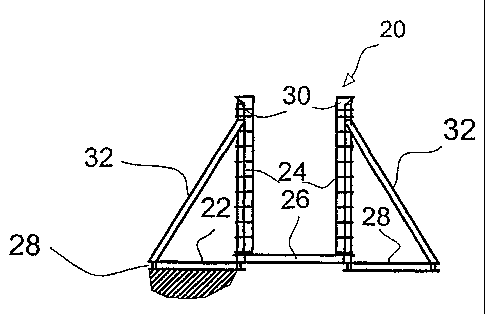
Figures 2 and 3 show plan and front view respectively
of a pile guide (20) embodying the present invention. The
pile guide (20) comprises a base frame (22) and a pile
guide member (24) mounted on the base frame (22). The
base. frame (22) comprises a generally U-shaped rigid
member (26) and a pair of substrate-engaging panels or
mudmats (28) which are releasably coupled to- the rigid=
member (26). The pile guide member (24 ') comprises a pair
of upright guide channels (30) mounted on the rigid member
(26) and supported by inclined struts (32) extending from
the peripheral corners of the base frame (22). The pile
guide (20) may be dismantled to improve ease of
.25 transportation, and, in particular, the base frame (22) constituents may
be decoupled into three more manageable
pieces, namely two tnudmats (28) and the rigid member (26).
Figure 4 illustrates the construction of the base
CA 02409694 2002-10-31
WO 01/92645 PCT/GB01/02389
9
frame (22) in more detail. The generally U-shaped rigid
member (26) forms the backbone of the structure and is
also fundamental to the operation of the pile guide (20).
The rigid member not only provides the points of anchorage
for the pile guiding member (24) and mudmats (28), but
also defines a central aperture (40) through which a pile
is driven into the substrate. Thereafter, the base frame
(22) may be disengaged from around the pile by moving the
base frame (22) to pass the pile through channel or
peripheral opening (42); the peripheral opening having a
span which exceeds the diameter of the pile. The mudmats
(28) are bolted to, and extend laterally of the sides (44)
of the rigid member. Thus, in use, the base frame (22)
may have a footprint covering something in excess of 100m2.
However, when being stored or in transit to the pile
driving site, the mudmats (28) may be detached from the
rigid member (26) to reduce the overall area which must be
made available to accommodate the pile guide.
As shown in Figure 4, the sides of the rigid member
(26) and mudmats (28) are provided with receptors (50) for
receiving the forks of fork-lift trucks. The receptors
(50) comprise a pair of flanges (52) forming an open
channel into which the prongs of a fork-lift may be
inserted. The uppermost flange in each pair then bears
the weight of the component during lifting. Padeyes (60)
are also provided at the corners of the rigid member (26)
for attaching lifting lines (e.g. cables) and thereby
lifting the base frame (22).
CA 02409694 2008-12-12
The pile guide member (24) illustrated in Figures 2
and 3 is just one of several different designs which could
be used in combination with the base frame (22). For
example, the pile guide member (24) could be replaced by a
pivoting/counterweighted arrangement as described in
W099/11872. Nonetheless, for completeness, the pile guide
member (24) will now be described in detail. The pile guide
member (24) is adapted to guide a pile having a pair of
diametrically opposed stabilising fins extending in an
axial direction along the curved periphery of the pile. The
pair of upright guide channels (30) are positioned opposite
each other with channel openings facing each other. In this
way, the channels receive and guide the stabilising fins
during pile driving. Once the pile has been driven into the
substrate (e.g. seabed) the pile guide (20) may be lifted
over the protuberant part of the pile to disengage the
stabilising fins from the pile guide member. Of course, if
the stabilising fins have been driven into the substrate,
the upright guide channels (30) no longer engage the pile,
and the pile guide (20) may disengage the pile by sliding
the pile guide (20) to pass the pile through the opening
(42).
Figures 5 and 6 show a pile follower (100) embodying
another aspect of the present invention. The pile
follower (100) is illustrated in use between a pile
driving hammer (102) and a finned pile (104), both of
which are shown in phantom lines. The pile follower (100)
CA 02409694 2002-10-31
WO 01/92645 PCT/GB01/02389
T1
has a pair of diametrically opposed fins (106) which are
configured to be a sliding fit inside the guide channels
(30) of pile guide (20). The pile follower (100) has an
end profile (110) comprising a driving face (112) and an
alignment ring (114). The alignment ring (114) comprises
a plurality of members (116) which extend axially beyond
the driving face (112). The alignment ring (114) is a
snug fit inside the bore (118) of the finned pile (104) to
achieve registration between the driving face (112) and
the exposed end of the finned pile (104).
The operation of the pile guide (20), the finned pile
(104) and the pile follower (100) will now be described to
illustrate the interaction therebetween. The pile guide
(20) is positioned on a substrate (e.g. seabed) and finned
pile (104) is loaded into the pile guide (20) with its
fins slidingly received in the upright guide channels
(30). The finned pile (104) is driven into the seabed as
far as the reciprocating motion of the drive hammer (102)
will allow. The drive hammer (102) is then raised clear
of the exposed end of the finned pile (104) so that
follower (100) may be fitted to it. The fins (106) of the
follower (100) are aligned with those of the pile (104) so
that the fins (106) are slidably received in the guide
channels (30). The alignment ring (114) engages the bore
of the finned pile (104) as the latter is lowered into
position, ensuring that the driving face (112) of the
follower (100) registers with and abuts the end of the
finned pile. The hammer (102) is then re-engaged, with
CA 02409694 2002-10-31
WO 01/92645 PCT/GB01/02389
12
the follower (100) now transmitting impact to the finned
pile (104) .