Language selection

Search

Patent 2409695 Summary

Third-party information liability

Some of the information on this Web page has been provided by external sources. The Government of Canada is not responsible for the accuracy, reliability or currency of the information supplied by external sources. Users wishing to rely upon this information should consult directly with the source of the information. Content provided by external sources is not subject to official languages, privacy and accessibility requirements.

Claims and Abstract availability

Any discrepancies in the text and image of the Claims and Abstract are due to differing posting times. Text of the Claims and Abstract are posted:

  • At the time the application is open to public inspection;
  • At the time of issue of the patent (grant).
(12) Patent: (11) CA 2409695
(54) English Title: UNIFORM DISPENSING DUAL CHAMBER SACHET
(54) French Title: SACHET A DEUX CHAMBRES A DISTRIBUTION UNIFORME
Status: Expired and beyond the Period of Reversal
Bibliographic Data
(51) International Patent Classification (IPC):
  • B65D 81/32 (2006.01)
  • B65D 75/32 (2006.01)
(72) Inventors :
  • FUQUEN, ORLANDO (United States of America)
(73) Owners :
  • COLGATE-PALMOLIVE COMPANY
(71) Applicants :
  • COLGATE-PALMOLIVE COMPANY (United States of America)
(74) Agent: SMART & BIGGAR LP
(74) Associate agent:
(45) Issued: 2008-06-17
(86) PCT Filing Date: 2001-05-09
(87) Open to Public Inspection: 2001-11-22
Examination requested: 2006-04-07
Availability of licence: N/A
Dedicated to the Public: N/A
(25) Language of filing: English

Patent Cooperation Treaty (PCT): Yes
(86) PCT Filing Number: PCT/US2001/014955
(87) International Publication Number: US2001014955
(85) National Entry: 2002-11-04

(30) Application Priority Data:
Application No. Country/Territory Date
09/569,664 (United States of America) 2000-05-12

Abstracts

English Abstract


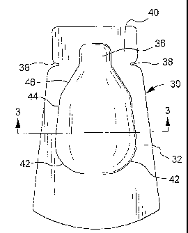
The present dual chamber sachet (30) overcomes the problem of non-uniform
dispensing when the sidewalls of the sachet are depressed. Through the use of
a relatively thin intermediate divider wall (48), rounded corner edges (42) at
the lower end of each chamber (32, 35) of the sachet, tapered side edges (44,
46) up to the exit channel (36) of each chamber of the sachet, and a
relatively wide dispensing opening uniform dispensing can be achieved. This
structure prevents the downward flow of substances in each chamber during
dispensing. The substances are directed upwardly by the rounded lower corners
of the sachet, the tapered upper walls and the wide dispensing opening. This
relatively wide dispensing opening minimizes the back pressure caused by the
substances flowing to a dispensing exit of a width less than that of the
product chambers.


French Abstract

Le sachet à deux chambres de l'invention (30) résoud le problème de distribution non uniforme lorsque les cloisons latérales du sachet sont enfoncées. Cette distribution uniforme est possible grâce à la présence d'une cloison intermédiaire de séparation relativement fine (48), d'angles arrondis (42) au niveau de l'extrémité inférieure de chaque chambre (32, 35) du sachet, de bords latéraux coniques (44, 46) au niveau du canal de sortie (36) de chaque chambre du sachet, et d'une ouverture de distribution relativement large. Cette structure empêche l'écoulement de substances dans les chambres lors de la distribution. Les substances sont dirigées vers le haut par les angles inférieurs arrondis du sachet, les cloisons supérieures coniques et la large ouverture de distribution. Cette ouverture de distribution relativement large réduit au minimum la contre-pression causée par les substances s'écoulant vers une sortie de distribution d'une largeur inférieure à celle des chambres de produit.

Claims

Note: Claims are shown in the official language in which they were submitted.


Claims
What is claimed is:
1. A dual chamber sachet for uniform dispensing of substances comprising a
front wall, rear wall and an intermediate divider wall, front wall and rear
wall peripheral edges of a first and second side edge, a lower edge and an
upper edge bonded together to form a container with two chambers with
Lower corners, the lower corners of said chambers being rounded, an upper
portion of said chambers having edges that taper to an exit channel
whereby upon depressing the front wall and rear wall of the sachet the
substances in the chambers are substantially uniformly dispensed.
2. A dual chamber sachet as in claim 1 wherein the upper edge portion of
said chambers have a first taper from said lower corners and a second taper
adjacent said exit channel, said second taper being at a greater angle than
said first taper.
3. A dual chamber sachet as in claim 1 wherein said exit channel extends
upwardly from said two chambers, an end of said exit channel distant from
said two chambers closed by the peripheral seal of the upper edge.
4. A dual chamber sachet as in claim 3 wherein adjacent said exit channel
there is at least one notch in at least one of the first and second side edge
whereby a portion of said channel at said at least one notch can be
removed to thereby open said exit channel.
5. A dual chamber sachet as in claim 4 wherein said notch is at the
commencement of said exit channel.
6. A dual chamber sachet as in claim 4 wherein the exit channel has a width
of about 35% to 65% that of the chambers at their widest point.
7. A dual chamber sachet as in claim 1 wherein said intermediate divider wall
has a thickness that is from about 10% to about 70% of that of either of
the rear wall or front wall.
-7-

8. A dual chamber sachet as in claim 7 wherein said intermediate divider wall
has a thickness that is form about 25% to about 50% of that of either of
the rear wall or front wall.
9. A dual chamber sachet as in claim 1 wherein the intermediate divider wall
is comprised of a barrier film selected from the group consisting of
monolayer and laminate films.
10. A dual chamber sachet as in claim 9 wherein the front wall and the rear
wall are comprised of a film selected from the group consisting of
monolayer and Laminate films.
11. A dual chamber sachet as in claim 1 wherein ratio of the length of the
container to the width of the container is about 1:1 to about 4:1.
12. A dual chamber sachet as in claim 11 wherein ratio of the length of the
container to the width of the container is about 1.5:1 to about 3:1.
-8-

Description

Note: Descriptions are shown in the official language in which they were submitted.


CA 02409695 2002-11-04
WO 01/87736 PCT/US01/14955
UNIFORM DISPENSING DUAL CHAMBER SACHET
Field of the Invention
This invention relates to a dual chamber sachet that substantially uniformly
dispenses the substances from each chamber when the sidewalls of the sachet
are
depressed. More particularly, this invention relates to a construction of a
dual
chamber sachet that provides for the uniform dispensing of the substances
stored
in each chamber of the dual sachet.
Background of the Invention
Sachets are small packets that are used for supplying small doses of a
product. These are used to dispense single or a small number of doses of
adhesives, lubricants, medicines, cosmetics, shampoos, conditioners, liquid
soaps,
lotions and dentifrices. In some instances a single dose is a sample amount. -
Regardless such sachets are commonly used to deliver a single dose of a
substance.
In most instances the sachets will be used to deliver a single dose of a
single
substance. However, in some instances they will be used to dispense doses of
two
different substances. Further, in most instances in the delivery of two
different
substances, these substances must be delivered substantially uniformly. That
is,
each of the substances should be dispensed in about equal amounts. This is
needed for the effective use of the substances being..dispensed. When the
substances are components of an adhesive they are reactive and must be
dispensed
and used in a certain reactive ratio. Medications also must be used in a
certain
ratio. The same is the case for a dentifrice that is comprised of two non-
compatible components. These types of substances need sachets that will
reliably
dispense the substances from each chamber in substantially uniform amounts.
The
3o present sachet is directed to solving this problem.
-1-

CA 02409695 2002-11-04
WO 01/87736 PCT/US01/14955
Brief Summary of the Invention
The present dual chamber sachet has a construction to facilitate the
uniform dispensing of substances. The sachet is. comprised of a front wall, a
rear
wall and an intermediate divider wall. The peripheral edges of a first and
second
side edge and of a lower and upper edge of the walls are bonded together to
provide a container with two separate chambers. The chambers have rounded
corners at a lower end of each chamber and in an upper part of each chamber
sidewalls which taper to a tapered exit channel. The exit channel has less of
a
.ro taper than the upper part of the chamber sidewalls. The exit channel
extends a
distance. from the top of the chambers. The exit channel will have a notch
adjacent the product chambers for the removal of a part of the exit channel
and
to thereby open the exit channel at about the commencement of the exit
channel.
The chambers of the sachet are sized so that the width of a person's thumb
will extend across a substantial portion of the width of the sachet. , This in
combination with an orifice that is about 75% to 100% the width of a
toothbrush, and about 35% to 65% of the width of the product chambers,
provides for a uniform dispensing from the sachet. In addition, the sachet
opens
2o at about the commencement of the tapered wall exit channel. This provides
for a
comparatively wide exit opening for the more uniform delivery of the products
from each of the chambers of the sachet. Further, the sachet is symmetrical
about
a vertical plane through the peripheral edges of the sachet.
The intermediate divider wall will have a thickness of about 10% to about
70% of that of either the front wall or rear wall, and preferably about 25% to
about 50%. Further, the intermediate divider wall will have good barrier
properties and will contain a film such as one selected from the group
comprising
polyethylene terephthalate, polypropylene, biaxially oriented polypropylene,
metal
folls, polyethylene, low density polyethylene, ethylene vinyl acetate
copolymers,
ethylene vinyl alcohol copolymers and polyacrylonitrile/styrene polymer
resins.
The front and rear walls will be comprised of a fiim selected from the same
polymers and copolymers. These will be used primarily in various laminate
structures.
-2-

CA 02409695 2007-10-31
62301-2291
2a
In accordance with an aspect of the invention,
there is provided a dual chamber sachet for uniform
dispensing of substances comprising a front wall, rear wall
and an intermediate divider wall, front wall and rear wall
peripheral edges of a first and second side edge, a lower
edge and an upper edge bonded together to form a container
with two chambers with lower corners, the lower corners of
said chambers being rounded, an upper portion of said
chambers having edges that taper to an exit channel whereby
upon depressing the front wall and rear wall of the sachet
the substances in the chambers are substantially uniformly
dispensed.

CA 02409695 2002-11-04
WO 01/87736 PCT/US01/14955
Brief Description of the Drawings
Figure 1 is a plan view of a prior art dual chamber sachet.
Figure 2 is a plan view of the present dual chamber sachet.
Figure 3 is a cross-sectional view of the dual chamber sachet of Figure 2
along line 3-3.
zo Figure 4 is a side elevational view of the dual chamber sachet.
Detailed Description of the Drawings
The sachet of this invention will now be described in its preferred
embodiments with reference to the drawings.
Figure 1 shows a prior art design for a dual chamber sachet. The sachet
10 has a peripheral seal area 12, a substance container 14 with an exit
channel
16. The exit channel 16 extends up into tab 20. Adjacent the exit channel
there
2o are notches 18 in the peripheral seal area. These notches define a weakened
area
where in a tearing motion the tab 20 can be removed from the sachet. This
opens the sachet for dispensing. The lower walls of this sachet, are angled at
about
90 at corners 22. The sidewalls 24 are essentially straight with a tapering
section 26 prior to a relatively narrow exit channel 16. Further, this sachet
is
opened near the end of the exit channel a distance from the product chambers.
A problem with this sachet design is that as the sachet walls are depressed
to dispense substances from each chamber of the sachet some of the substances
will be forced downward into areas of corners 22 of the sachet. This substance
will not be dispensed. This is the result of the essentially 90 oangle to the
lower
corners, the straight sidewalls and relatively narrow dispensing opening.
Further,
depending on how the sachet is being held during dispensing, more of the
substance in one chamber will be flowed into the corners than that in another
chamber. The result is non-uniform dispensing.
In Figure 2 there is shown a sachet that overcomes these problems of non-
uniform dispensing. The sachet 30 has a peripheral area 32 and a substance
-3-

CA 02409695 2002-11-04
WO 01/87736 PCT/US01/14955
chamber area 34. There is a dispensing channel 36 and a tab 40. Notches 38
provide a weakened point for the removal of tab 20 to thereby open exit
channel
36 for dispensing the substances from the chamber area 34. The chamber has
rounded lower corners 42, tapering lower sidewalls 44 and increased tapering
upper sidewalls 46. The rounded corners 42 prevent the substance in each
chamber from flowing into the corners during a dispensing. The wide exit
channel
results in a- decreased resistance to flow of product from the sachet. The
exit
channel has a width of about 35% to about 65% of the width of the substance
chambers at their widest point.
Figure 3 shows the sachet in cross-section. There is shown a front wall 50,
intermediate divider wall 48 and a rear wall 52. This structure forms chambers
54 and 56.
The sachet has a chamber area that has a width of about 50% to about
100% of the width of a person's thumb. This, in combination, with round lower
edges, tapering sidewalls, and an exit channel having a width that is about
75% to
about 100% of the width of a toothbrush provides a uniform dispensing from the
sachet. Further , in a preferred embodiment the sachet is symmetrical about a
vertical plane through the peripheral area 32. This all contributes to the
uniform
dispensing from the sachet.
Figure 4 shows the sachet in a side elevational view. This view shows the
sachet as being symmetrical about a plane through the peripheral area 32. The
divider wall 18 lies in this plane. This divider wall forms the chambers 54
and
56. This view shows the rounder, lower corners 42, first tapered sidewalls 44
and second tapered sidewalls 46. The second tapered sidewalls have a greater
taper than the first tapered sidewalls.
The outer walls 50 and 52 mill usually be the same material. These walls
can be of a monolayer or a multilayer film structure. Suitable films are set
out in
the following Table 1 where PET is polyethylene, terephthalate; Barex is
polyacrylonitrile and polystyrene resin; BOPP is biaxially oriented
polypropylene;
LDPE is low density polyethylene; PE is polyethylene; and EVOH is ethylene-
vinyl
alcohol copolymer.
-4-

CA 02409695 2002-11-04
WO 01/87736 PCT/US01/14955
Table l
PET/Aluminum Foil IBarex
PET/Aluminum Foil /LDPE
BOPP /Aiuminum Foil /Barex
BOPP /Aluminum Foil /LDPE
LDPE/EVOH/LDPE
PET/EVOH/LDPE
BOPP/EVOH/LPDE
LPDE Based Monolayer Or Polyefins Blend
Sealable PET Based Monolayer
PET/PE/ Sealable PET
PET/Foil/ Sealable PET
Nylon/ Foil/PE
NylonlPE/ Sealable PET
The intermediate divider wall is comprised of a barrier film which likewise
can be of a monolayer or a multilayer structure. Suitable films are set out in
Table 2.
Table 2
LPDE Based Or Polyefns Blend Monolayer
Barex Monolayer
LDPE/Aluminum Foil /LDPE
Barex/Aiuminum Foil /Barex
LDPE/EVOH/ LDPE
Seaiable PET/PE/ Sealable PET
Sealable PET/Foil/ Sealable PET
PE /Nylon/ PE
-5-

CA 02409695 2002-11-04
WO 01/87736 PCT/US01/14955
The packets are made from three flms bonded together at their periphery.
The bonding is by a heat sealing. In this regard the layers that are in
contact and
that are to be heat bonded together must be head bondable to each other.
Suitable selections can be made from Table 1 and Table 2. Usually the sachet
will
be formed and filled in a continuous operation. The printing and decoration
will
be on the f im outer walls when the webstocks are fed to a sachet making
station.
The sachets can be made from various materials with those that are
preferred set out in Table 1 and Table 2. In addition, the sachets can be
formed
ro and filled in a continuous process or the sachets made and later filled.
The
primary factor in the present sachet is the shape of the sachet product
chambers
to deliver a uniform amount of the product in each chamber when squeezed to
dispense the products.
-6-

Representative Drawing
A single figure which represents the drawing illustrating the invention.
Administrative Status

2024-08-01:As part of the Next Generation Patents (NGP) transition, the Canadian Patents Database (CPD) now contains a more detailed Event History, which replicates the Event Log of our new back-office solution.

Please note that "Inactive:" events refers to events no longer in use in our new back-office solution.

For a clearer understanding of the status of the application/patent presented on this page, the site Disclaimer , as well as the definitions for Patent , Event History , Maintenance Fee  and Payment History  should be consulted.

Event History

Description Date
Time Limit for Reversal Expired 2018-05-09
Change of Address or Method of Correspondence Request Received 2018-03-28
Letter Sent 2017-05-10
Grant by Issuance 2008-06-17
Inactive: Cover page published 2008-06-16
Inactive: Final fee received 2008-04-03
Pre-grant 2008-04-03
Letter Sent 2007-11-21
Amendment After Allowance Requirements Determined Compliant 2007-11-21
Inactive: Amendment after Allowance Fee Processed 2007-10-31
Amendment After Allowance (AAA) Received 2007-10-31
Notice of Allowance is Issued 2007-10-10
Letter Sent 2007-10-10
Notice of Allowance is Issued 2007-10-10
Inactive: IPC removed 2007-10-09
Inactive: Approved for allowance (AFA) 2007-09-11
Letter Sent 2006-05-02
Request for Examination Requirements Determined Compliant 2006-04-07
All Requirements for Examination Determined Compliant 2006-04-07
Request for Examination Received 2006-04-07
Inactive: IPC from MCD 2006-03-12
Letter Sent 2003-02-26
Inactive: Correspondence - Transfer 2003-02-21
Inactive: Courtesy letter - Evidence 2003-02-11
Inactive: Cover page published 2003-02-07
Inactive: Notice - National entry - No RFE 2003-02-05
Inactive: Single transfer 2003-01-16
Application Received - PCT 2002-12-12
National Entry Requirements Determined Compliant 2002-11-04
Application Published (Open to Public Inspection) 2001-11-22

Abandonment History

There is no abandonment history.

Maintenance Fee

The last payment was received on 2008-03-25

Note : If the full payment has not been received on or before the date indicated, a further fee may be required which may be one of the following

  • the reinstatement fee;
  • the late payment fee; or
  • additional fee to reverse deemed expiry.

Patent fees are adjusted on the 1st of January every year. The amounts above are the current amounts if received by December 31 of the current year.
Please refer to the CIPO Patent Fees web page to see all current fee amounts.

Owners on Record

Note: Records showing the ownership history in alphabetical order.

Current Owners on Record
COLGATE-PALMOLIVE COMPANY
Past Owners on Record
ORLANDO FUQUEN
Past Owners that do not appear in the "Owners on Record" listing will appear in other documentation within the application.
Documents

To view selected files, please enter reCAPTCHA code :


To view images, click a link in the Document Description column. To download the documents, select one or more checkboxes in the first column and then click the "Download Selected in PDF format (Zip Archive)" or the "Download Selected as Single PDF" button.

List of published and non-published patent-specific documents on the CPD .

If you have any difficulty accessing content, you can call the Client Service Centre at 1-866-997-1936 or send them an e-mail at CIPO Client Service Centre.


Document
Description 
Date
(yyyy-mm-dd) 
Number of pages   Size of Image (KB) 
Abstract 2002-11-03 1 62
Description 2002-11-03 6 270
Representative drawing 2002-11-03 1 6
Drawings 2002-11-03 1 18
Claims 2002-11-03 2 68
Description 2007-10-30 7 288
Representative drawing 2008-05-20 1 7
Reminder of maintenance fee due 2003-02-04 1 106
Notice of National Entry 2003-02-04 1 189
Courtesy - Certificate of registration (related document(s)) 2003-02-25 1 130
Reminder - Request for Examination 2006-01-09 1 116
Acknowledgement of Request for Examination 2006-05-01 1 190
Commissioner's Notice - Application Found Allowable 2007-10-09 1 164
Maintenance Fee Notice 2017-06-20 1 178
PCT 2002-11-03 5 192
Correspondence 2003-02-04 1 24
Correspondence 2008-04-02 1 40