Note: Descriptions are shown in the official language in which they were submitted.
CA 02410439 2002-11-18
WO 02/071039 PCT/IB02/00563
- 1 -
A METHOD FOR MEASURING HEMOGLOBIN CONCENTRATION (HGB) IN THE
BLOOD IN A CIRCUIT OF A DIALYSIS MACHINE, MEASURING DEVICE
AND CIRCUIT FOR THE APPLICATION OF THE METHOD
DESCRIPTION
The present invention relates to a method for measuring
hemoglobin concentration in the blood in a circuit of a
dialysis machine.
Generally, a dialysis machine of the known type
comprises a first circuit for blood circulation, connected,
when in use, to the circulatory system of a patient, a second
circuit for the circulation of, dialysate, and a filter,
through which the first circuit passes the blood and the
second circuit passes the'dialysate. The filter comprises a
semi-permeable membrane which, when in use, separates the
dialysate from the blood, and permits an exchange of ions
between the dialysate and the blood and the transfer of some
of the blood plasma through the membrane. The first circuit
comprises an arterial branch located up-line from the filter
and a venous branch located down-line from the filter, while
the machine comprises a peristaltic pump located in the
arterial branch to convey the blood extracted from the
patient to the filter. The first and second circuits are made
from transparent flexible material, such as PVC, to ensure
the asepsis of the circuit. The flexibility of the circuits
facilitates their packaging and enables the flow to be
blocked by a simple constriction of a section of the circuit,
while the transparency makes it possible to visually inspect
the liquids being conveyed in the circuit during use.
There is a known way of determining the concentration of
hemoglobin in the red corpuscles during the dialysis
treatment, by means of highly accurate measurements of an
intrusive kind, which require the laboratory examination of
blood samples. Other dialysis machines enable non-intrusive
measurements of the hemoglobin concentration to be made
within the machine. The non-intrusive measurements made
within the machine are markedly less accurate than laboratory
CA 02410439 2002-11-18
WO 02/071039 PCT/IB02/00563
2 -
measurements, but have the advantage of being provided in
real time in such a way that the operating parameters of the
dialysis machine can be corrected instantaneously.
The patent IT 1,240,489 discloses a method of measuring
the hemoglobin concentration within the machine and in a non-
intrusive way, by measuring the absorption of electromagnetic
waves of the blood flowing in the arterial branch of the
first circuit.
Hemoglobin is a protein contained in the red corpuscles,
and its concentration modifies the pigmentation of the red
corpuscles; the concentration of hemoglobin in the blood
therefore depends on the quantity of red corpuscles contained
in the blood and on the quantity of hemoglobin contained in
the red corpuscles. To measure the absorption of
electromagnetic waves by the blood, an emitter is used to
emit a beam of electromagnetic waves having an emission
intensity correlated with an emission signal, the beam of
electromagnetic waves is made to strike a section of the
circuit, and a beam of electromagnetic waves is detected by
means of a receiver which emits a signal correlated with the
reception intensity. The difference between the emitted
intensity and the received intensity corresponds to the
absorption, which is correlated with the hemoglobin
concentration by a specific function.
Although the described method has been shown to provide
an accurate measurement, laboratory tests conducted by the
applicant have demonstrated that, in some cases of operation
of the dialysis machine, the measurement made according to
the method described above supplies values of hemoglobin
concentration which deviate from the concentration values
measured in the laboratory for the same type of blood.
The object of the present invention is to provide a
method for measuring the hemoglobin concentration in the
blood in a circuit of a dialysis machine in a non-intrusive
way, and with a level of accuracy which is as close as
possible to the level of accuracy of laboratory measurement.
According to the present invention, a method is provided
for measuring the hemoglobin concentration in the blood in a
CA 02410439 2010-02-23
3
circuit of a dialysis machine, the method comprising the
measurement of the absorption of electromagnetic waves by the
blood along one section of the said circuit, the values of
the said absorption being correlated with the values of the
said hemoglobin concentration; the method being characterized
in that the values of at least one physical quantity of the
blood, from the group comprising blood pressure, blood
temperature and the rate of flow of blood along the said
section, are measured, and the values of hemoglobin
concentration in the blood are calculated as a function of
the values of absorption and of the said physical quantity.
The present invention also relates to a circuit for the
application of the aforesaid method.
According to the present invention, a blood circulation circuit for dialysis
machine, comprises a connection forming a section of the circuit, the said
connection comprising a tube for subjecting the blood to the measurement of
the
absorption of electromagnetic waves and a chamber for subjecting the blood to
the
measurement of pressure.
The present invention relates to a device for measuring
a characteristic of the blood in a circuit of a dialysis
machine.
According to the present invention, a device is provided
for measuring the hemoglobin concentration in a circuit, of a
dialysis machine comprising a connection forming a section of
the said circuit, the said connection comprising a tube along
which a measurement is made by means of beams of
electromagnetic waves to determine the absorption of the
blood, the hemoglobin concentration being correlated with the
said absorption, the device being characterized in that it
comprises at least one further sensor for measuring one of
two quantities, namely the blood pressure and the blood
temperature; the hemoglobin concentration being a function of
the absorption and of the said quantity.
CA 02410439 2002-11-18
WO 02/071039 PCT/IB02/00563
4 -
The present invention will now be described with
reference to the attached drawings, which show, without
restrictive intent, an example of embodiment in which
Figure 1 is an experimental graph showing the hemoglobin
concentration as a function of the received intensity;
- Figure 2 is an experimental graph showing the error of
measurement of the hemoglobin concentration as a function of
the blood temperature;
Figure 3 is an experimental graph showing the error of
measurement of the hemoglobin concentration as a function of
the blood pressure;
Figure 4 is an experimental graph showing the error of
measurement of the hemoglobin concentration as a function of
the blood flow;
- Figure 5 is a schematic view of a dialysis machine for
implementing the method according to the present invention;
- Figure 6 is a side elevation of an element of the device
for implementing the present invention;
Figure 7 is a plan view of the element of Figure 6;
Figure 8 is a graph of received intensity as a function
of time in a first operating condition of the machine of
Figure 5; and
Figure 9 is a graph of received intensity as a function
of time in a second operating condition of the machine of
Figure 5.
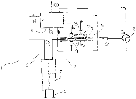
With reference to Figure 5, the number 1 indicates the
whole of a dialysis machine for carrying out dialysis
treatments on patients suffering from kidney failure. The
machine 1 comprises a blood circuit 2, a dialysate circuit 3,
and a filter 4. In use, the circuit 2 is connected to the
circulatory system of a patient and supplies the blood taken
from the patient to the filter 4 along an arterial branch 5
and returns the blood to the patient along a venous branch 6.
The filter 4 comprises a semi-permeable membrane 7, which
separates the blood from the dialysate and permits an
exchange of ions between the blood and the dialysate and the
extraction of some of the blood plasma from the blood circuit
2. The machine 1 comprises a peristaltic pump 8, which is
CA 02410439 2010-02-23
located on the arterial branch 5 and, in use, extracts the
blood from the patient and conveys the blood to the filter 4,
and a measuring device 9 for measuring hemoglobin
concentration (HGB) in the blood along the arterial branch 5
in a non-intrusive way.
The measuring device 9 comprises a connection 10 located
between the peristaltic pump 8 and the filter 4, a sensor 11
of the optical type, a pressure sensor 12, a temperature
sensor 13 and a calculation unit 14 connected to the sensors
11, 12 and 13. With reference to Figure 1, the connection 10
forms a section 5a of the arterial branch 5 and is interposed
between two flexible sections 5b and 5c of the arterial
branch 5.
With reference to Figures 6 and 7, the connection 10
comprises a tube 15 and a chamber 16 rigidly connected to the
.tube 15; the tube 15 is integral with the chamber 16 and both
are made from transparent rigid plastic. The chamber and/or
the tube may integrally carry a radial element protruding
from the surface of connection 10 in the form of a little fin
(not shown) that may serve to easily handle the connector and
as positioning device to easily mount and fix the connector
onto a machine. The tube 15 comprises an opening 17 for
connection to the section 5b, an opening 18 for connection to
the section 5c, a portion 19 adjacent to the chamber 16 and a
portion 20, which has. an internal diameter Di and is located
between the opening 17 and the portion 19. The chamber 16
comprises a container 21, a cover 22 provided with a central
hole 23 and an elastic membrane 24, which is gripped between
the container 19 and the cover 22 and is deformed as a
function of the blood pressure. In other words, the pressure
sensor 12 comprises the chamber 16 and an electric device 25
for measuring the extent of deformation of the membrane 24 in
the form of an electrical signal acquired by the calculation unit 14.
CA 02410439 2010-02-23
6
The sensor 11 comprises an emitter 26 for emitting a beam of
electromagnetic waves in the visible, or "NIR", spectrum, and for guiding the
beam
of electromagnetic waves along the portion 20 of the tube 15 and a detector 27
for
receiving a beam of electromagnetic waves on the opposite
side of the tube 14. The sensor 11 is described in detail in
the patent IT 1,240,489, whose content is included by
reference in the present description.
The temperature (T) sensor 13 is a sensor of
electromagnetic waves which are outside the visible or NIR
spectrum.
In use, the peristaltic pump 8 provides a flow of blood
Qb along the circuit 2 as indicated by the arrow in Figure 1
and through the connection 10. The peristaltic pump 8
supplies the values of the flow Qb to the calculation unit 14 at successive
instants.
The sensor 12 transmits electrical signals correlated to
the pressure values P at successive instants to the
calculation unit 14, while the sensor 13 supplies electrical
signals correlated with the values of temperature T to the
calculation unit 14. The blood flowing along the portion 20
of the tube 15 forms an optical path which is correlated with
the internal diameter Di of the portion 20, while the
detector 27 receives a beam of electromagnetic waves on the
opposite side of the portion 20. The emitted beam is
correlated with a signal of emitted intensity Io and the
received beam generates a signal of received intensity IR.
The calculation unit 14 receives, in a time sequence with
constant intervals, the values of the received intensity IR
for a constant emitted intensity I. In practice, the
absorption A is equal to the emitted intensity Io minus the
received intensity IR.
The measurement of the hemoglobin concentration HGB is
based on studies carried out by the applicant, who, by means
of experimental tests, has correlated the hemoglobin
CA 02410439 2010-02-23
6a
concentration HGB with the absorption A, in other words with
the received intensity signal IR for a constant emitted
intensity signal 10, as shown in the graph of Figure 1.
The applicant has determined the error of measurement of
the hemoglobin concentration HGB as a function of the blood
pressure P as shown in Figure 3, as a function of the blood
CA 02410439 2002-11-18
WO 02/071039 PCT/IB02/00563
7 -
flow Qb as shown in Figure 4, and as a function of
temperature T as shown in Figure 2.
The applicant's studies have demonstrated that the blood
flow Qb, the pressure P, and the temperature T modify the
blood's capacity for absorption (A) of electromagnetic
radiation, in other words the absorption A, and cause a
deviation between the values of hemoglobin concentration HGB
found in the machine and those found in laboratory tests. In
other words, the physical quantities acting on the blood
during the operation of the machine 1 cause structural
modifications of the red corpuscles, which, although small,
are sufficient to alter the measurement of the hemoglobin
concentration HGB. In particular, when the pressure P
increases the red corpuscles are flattened, while the flow Qb
causes an orientation of the red corpuscles and the
temperature T causes a change in the dimensions of the
corpuscles.
Measurements were made on the basis of the studies
carried out by the applicant, and by means of the measuring
device 9, and their accuracy was found to increase with an
increase in the allowance made for the physical quantities
which modify the structure of the red corpuscles.
The value of the internal diameter Di is set in the
calculation unit 14, which receives the value of the flow Qb
and calculates the hemoglobin concentration HGB as a function
of the values of absorption A of electromagnetic waves, of
the pressure values P measured by the sensor 12, of the flow
Qb of the pump 8, and of the values T measured by the sensor
13.
In practice, the following function relating the
hemoglobin concentration to the aforesaid quantities was
calculated on the basis of the studies which were carried
out:
IR F )
HGB = In 10 f( b,P,Di,T)LIn 1- IA 11 = f(QB,P,Di,T)
L o J
This function can also be simplified, since eliminating
the dependence on one or two of the measured physical
quantities, consisting of the pressure P, the flow Qb and the
CA 02410439 2002-11-18
WO 02/071039 PCT/IB02/00563
8 -
temperature T, will provide a measurement of the hemoglobin
concentration HGB which is less accurate than the measurement
in which the function takes into account all three of the
measured physical quantities, but is still more accurate than
a measurement based solely on the absorption A, and is closer
to the laboratory measurements.
The structure and functional working of the connection 10 is
important in order to properly compensate the measurement of
HGB as a function of the pressure. Indeed the amplitude,
period and variable components of pressure in the tube 15
(the pressure is constantly modulated by the blood pump 8)
influence the HGB measurement. Since the tube 15 and the
chamber 16 are directly engaged one another and both made of
rigid material the pressure detection in the chamber 16 is
very precise and strictly related to the pressure and to the
pressure variations in tube 15. Moreover, given the close
proximity between tube 15 and chamber 16 and the rigidity of
connection 10, it is practically impossible to deform the
blood conduit between the section where the optical detection
is carried out and the section where the pressure detection
is obtained. The axial distance between the cross section of
the portion 20 of tube 15 where the optical detection is
carried out and the cross section of chamber 16 where the
pressure detection is obtained shall be less than 50 mm; in
the embodiment shown in the figures 6 and 7 such a distance
is equal to 25 mm. The portion 20 of tube 15 shall present an
internal diameter Di less than 10mm.
With reference to Figures 8 and 9, the graphs show a
curve of the intensity IR received by the detector 27 as a
function of time t and a curve of the values of the variance
VAR of the curve of received intensity IR as a function of
time t.
With reference to Figure 8, the curve of the values of
IR comprises a first section 28, which is characterized by a
cyclical variation of the values of IR caused by the flow Qb
provided by the peristaltic pump 8 and corresponds to a
normal stage of operation of the dialysis machine 1, and a
section 29 which corresponds to a stage in which a blockage
CA 02410439 2002-11-18
WO 02/071039 PCT/IB02/00563
- 9 -
of the circuit has occurred up-line from the sensor 11.
Although the divergence between the values of IR of the
section 28 and those of the section 29 is significant in
graphic terms, it is difficult, in terms of the signal, to
establish a threshold which clearly distinguishes the section
28 from the section 29. Conversely, the variance VAR shows a
peak tending towards infinity at the point of the change from
the section 28 to the section 29, in other words at the
instant when the blockage of the circuit 2 occurs.
With reference to Figure 9, the curve of the received
intensity IR comprises a first section 30 which corresponds
to a stage of normal operation of the machine 1, and a
section 31 which corresponds to a stage in which a blockage
of the circuit has occurred down-line from the sensor 11,
which does not cause a significant variation of the received
intensity IR. Conversely, the down-line blockage causes a
significant variation of the variance VAR as a function of
time t.
The calculation unit 14 constantly compares each value
of the variance VAR with a range of acceptability in the
region of a mean value of the values of variance VAR
corresponding to the normal operation of the machine 1, in
other words without blockages of the circuit 2. If the value
of the variance VAR diverges significantly from the range of
acceptability, the calculation unit 14 emits an error signal
E.
Consequently, the measurement of the absorption A is
used not only to measure the hemoglobin concentration HGB,
but also to discover whether a blockage has occurred up-line
or down-line from the sensor 11 in the arterial branch S.