Note: Descriptions are shown in the official language in which they were submitted.
CA 02410870 2002-11-27
WO 01/91910 PCT/USO1/17590
COMBINATION SPRAY APPARATUS
CROSS-REFERENCE TO RELATED APPLICATIONS: NONE
STATEMENT REGARDING FEDERALLY SPONSORED RESEARCH OR
DEVELOPMENT: NONE
BACKGROUND OF THE INVENTION
This invention relates generally to apparatus for mixing and spraying fluid
materials. More particularly, it relates to such apparatus wherein the
selection of
sprayable materials can be made in conjunction with the apparatus.
BACKGROUND ART
It is customary to provide a single nozzle or wand from which can be
sprayed a variety of fluid materials. For example, at a do-it-yourself car
wash,
soap, water and wax can be sprayed fiom a single wand. However, the selection
of these materials must be made at a site remote from the wand.
It is also lmown in the art to provide dispensing apparatus for dispensing
different materials through a nozzle. For example, in U.S. patent 5,476,193, a
beverage dispensing apparatus is disclosed which dispenses through a nozzle a
preestablished volume of a syrup and a preestablished volume of a soda to be
intermixed within a nozzle prior to being dispensed into a container. In U.S.
patent 4,836,414 a premixed dispensing system is disclosed wherein several
beverages can be selected by pushing independent selection buttons which
control
independent dispensing valves and independent nozzles. A three-grade gasoline
dispensing system wherein an intermediate grade is provided by mixing two
other
grades through pump arrangement is described in U.S. patent 3,717,283.
CA 02410870 2002-11-27
WO 01/91910 PCT/USO1/17590
2
SUMMARY OF THE INVENTION
The prior art does not provide a sprayer device which provides for the
selection of different sprayable materials and can dispense the different
fluid
materials from a single body member.
It is an advantage of the invention to provide a sprayer apparatus which
affords a selection of sprayable materials in direct conjunction with the
sprayer
device.
It is another advantage of the invention to provide a sprayer apparatus of
the foregoing type which can mix two fluid materials.
It is still another advantage of the invention to provide a sprayer apparatus
which has a siphoning function for a fluid material.
It is yet another advantage of the invention to provide a sprayer apparatus
which is easily manipulated.
The foregoing advantages are accomplished in one aspect by the sprayer
apparatus of this invention which includes a main body portion with a flow
passage formed through the main body portion. A first barrel and a second
barrel
are in fluid communication with the flow passage. A first valve member is
connected to the first barrel and a second valve member connected to the
second
barrel with both the first and second valve members operatively associated
with
the flow passage.
In another aspect, an additional flow passage is in fluid communication
with the second barrel.
In a preferred embodiment, an eductor is operatively associated with the
second barrel.
In another preferred embodiment, there are two flow passages in fluid
communication with the eductor.
In still another aspect, there are two valve members each connected to one
of the two flow passages and constructed and arranged to separately open and
close the two passages, the two valve~members are operable by a single control
apparatus which includes a first gear with a camrning surface and a second
meshed gear which operates the second valve member.
CA 02410870 2002-11-27
WO 01/91910 PCT/USO1/17590
3
In yet another aspect, the second valve member is an on/off valve and the
first valve member includes a trigger mechanism.
BRIEF DESCRIPTION OF THE DRAWINGS
Fig. 1 is a side view of the sprayer apparatus of this invention.
Fig. 2 is a view similar to Fig. 1 with portions broken away.
Fig. 3 is a partial exploded view of the sprayer apparatus.
Fig. 4 is an exploded view of a valve member for use in the sprayer
apparatus.
Figs. 5 and 6 are sectioned views of the valve member shown in Fig. 4.
DESCRIPTION OF PREFERRED EMBODIMENTS
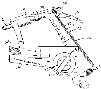
As shown in Figures 1 and 2, the combination spray apparatus generally
10 includes a body 12 having a first barrel 14 and a second barrel 16. A spray
head 18 extends from barrel 14 and a second spray head 20 extends from barrel
16. A liquid passage 22 in the form of a hollow tube is disposed inside the
body
12. It has internal threads 23 for connection to a source of liquid such as a
hose.
Fluid passage 22 connects also with a hollow handle 24 of a typical trigger
nozzle
such as sold by the Gilmour Company in Louisville, KY. It includes a handle
grip portion 26 which controls a rod 28 inside nozzle portion 30. Connected to
nozzle portion 30 is an attaclnnent member 32 having a nut 34 for connecting
to
nozzle portion 30. A second nozzle portion 33 connects to the attachment
member 32 by means of the nut 36. The spray head 18 slidably engages the
second nozzle portion 33.
When a source of liquid is connected to liquid passage 22, it will flow
through the handle grip portion 30 and the flow controlled in nozzle portion
30 by
the rod 28 and the trigger lever 26. The flow will continue through the
attaclunent
member 32 and into the second nozzle portion 33 where the adjustment of the
spray will be controlled by the spray head 18.
CA 02410870 2002-11-27
WO 01/91910 PCT/USO1/17590
4
A branch liquid passage 38 is also in fluid communication with liquid
passage 22. It supplies liquid to a valuing device 40 of the on/off type. It
is
connected to the branch fluid passage by the nut 42. An eductor 44 of the type
disclosed in U.S. patent 5,927,338 connects to the valuing device 40 and
includes
an inlet port 46 to which is connected the supply lines 48 and 50. The
adjustable
spray head 20 engages the eductor 44 at the end thereof.
Referring to Figure 3 it is seen that there are two valves 52 and 54 to
which liquid flow is regulated through the lines 48 and 50 to the eductor 44.
Liquid is supplied to these valves by the lines 58 and 57. Suitable fittings
such as
53, 51, 55 and 56 are provided on the valves 52 and 54, respectively for this
purpose. Lines 57 and 58 are in fluid communication with inlet fittings such
as 59
extending from housing 60. The flow of liquid through the valves 52 and 54 is
controlled by the gear 70 which has the axle 72 for rotatably fitting into
collar 74
which is connected to the body 12. Valves 52 and 54 are also secured to body
12
and are actuated by the contact of the~cam surface 76. Gear 70 drives gear 68
which has the cap 66 for engagement with the stem 64 of the valve 40.
Each of the valves 52 and 54 are of the same construction. Accordingly,
only valve 52 is shown in detail in Figures 4 - 6. It includes the valve body
84 in
which is slidably mounted a plunger 86 having a seal portion 88. The plunger
is
activated by the cam contact 80 which is guided over the valve body 84 by the
flange section 78. A spring 82 biases the cam contact upwardly as well as the
plunger 86 with respect to the housing 84. Valve 52 is shown in the closed
position in Figure 5. There it will be seen that the seal portion 88 is
positioned in
the channel 89 formed between the housing 84 and the valve cap 92. An
appropriate seal 90 is placed between the housing 84 and the cap 92. A slot 85
is
provided in the housing 84 to accommodate the end section 83 of the seal
portion
88. This affords a seal tight condition for the valve when the plunger is in
the
closed position
Figure 6 represents the valve 52 in an open position. As shown, the cam
contact 80 has been moved downwardly and accordingly so has the plunger 86.
This causes the seal portion 88 to move downwardly and out of the channel 89
thereby permitting liquid flow from inlet 51 to outlet 53.
CA 02410870 2002-11-27
WO 01/91910 PCT/USO1/17590
OPERATION
5 A better understanding of the combination spray apparatus 10 as well as
its unique features will be had by description of its operation. A source of
water
such as from a hose is connected to the threads 23 and the fluid passage 22. A
source of detergent such as Break-Up, available from Johnson Wax Professional
of Sturtevant, Wisconsin, is connected to the inlet 59. A source of sanitizer
such
as J-512, also available from Johnson Wax Professional, is connected to a
similar
inlet through housing 60 which is in fluid communication with the line 57. The
end 19a of the handle 19 of the control knob 17 is placed in a 12 o'clock
position
as viewed in Fig. 1. In this position valve 40 is in a closed position so that
no
water is flowing through the eductor 44. Water flows through the handle grip
portion 24 of the trigger nozzle 11 as well as the nozzle portion 30. Water is
sprayed through the spray head 18 by means of the activation of the trigger
lever
26. After suitable spraying has taken place, the detergent can then be applied
by
means of the eductor 40. This is accomplished by turning the handle 19 in a
counter-clockwise position so that the end 19a is in a 9 o'clock position.
Before
this movement, it will be appreciated that valve 40 is in a closed position so
that
no water is flowing through the eductor. When handle 19 is moved to the
previously mentioned 9 o'clock position valve 40 will open allowing water to
flow through the eductor. This is effected by a cap (not shown) on the inside
of
knob 17 engaging the axle 73 (see Fig. 2) of gear 70 which in turn rotates
gear 68
and the stem 64. At the same time, the inside cam surface 76 of gear 70 will
move over the cam contact 81 of valve 54 to allow a siphoning of detergent
from
line 58 through the valve 54, through line 48, to the eductor 44 and
consequently
out through the spray head 20. After the application of the detergent, it may
be
desirable to apply a sanitizer. This is accomplished by rotating the handle 19
and
the end portion 19a to a 3 o'clock position. This opens the valve 40 by the
opposite rotation of gear 68 as well as opens the valve 52 by movement of the
cam surface 76 over the cam contact 80 of valve 52. This allows a siphoning of
CA 02410870 2002-11-27
WO 01/91910 PCT/USO1/17590
6
sanitizes from line 57, through valve 52, through line 50 to supply sanitizes
to the
eductor 44 and ultimately the spray head 20.
It should be pointed out that the eductor described in U.S. patent
5,927,388 is particularly suitable for use with the combination spray
apparatus.
This is because of its back-flow tolerances which substantially reduces the
chance
of liquid flowing back though the air gap irrespective of any back pressure
created
by the spray head 20.
Referring to Figs. 4 and 6, it is seen that tl2e spring 82 is accommodated in
housing 84 in a manner to be isolated from the flow passage through the valve
52
as represented by the input and output passages 95 and 96, respectively, and
the
channel 89. This protects the spring 82 from contact with any corrosive or
degrading fluid materials in the passages and channel.
Another feature of the valves 52 and 54 is the configuration of the plunger
86. As best seen in Figs. 5 and 6 the seal portion is of a turned up J-shaped
configuration so that a sealing mechanism is located along and parallel to the
direction of motion of the plunger and not perpendicular. This assures that
any
wearing of the plunger surfaces does not degrade the quality of the seal as no
wear occurs on the major sealing surface.
It will thus be seen that there is now provided a combination spray
apparatus which can afford the selection of materials to be sprayed directly
in
conjunction with the spray apparatus and without having to move to a control
source. This is advantageous not only from a time saving standpoint but also
from the standpoint of convenience where the spraying nozzle may be used in a
difficult to reach position. The combination spray apparatus of this invention
has
been illustrated for use in conjunction with the spraying of both a detergent
and an
sanitizes material. It is obvious that it could be utilized to advantage with
only the
spraying of one additional material such as the detergent or the sanitizes.
This can
be accomplished through utilization of only one of the valve members such as
52
or 54. Further, while a particular trigger nozzle has been indicated for use
in the
combination spray apparatus, other styles and designs could be incorporated.
Neither is the particular design of the body I2 of critical importance. Other
geometric configurations could also be utilized. All such and other
modifications
CA 02410870 2002-11-27
WO 01/91910 PCT/USO1/17590
within the spirit of the invention are meant to be within its scope as defined
by the
appended claims.