Language selection

Search

Patent 2411759 Summary

Third-party information liability

Some of the information on this Web page has been provided by external sources. The Government of Canada is not responsible for the accuracy, reliability or currency of the information supplied by external sources. Users wishing to rely upon this information should consult directly with the source of the information. Content provided by external sources is not subject to official languages, privacy and accessibility requirements.

Claims and Abstract availability

Any discrepancies in the text and image of the Claims and Abstract are due to differing posting times. Text of the Claims and Abstract are posted:

  • At the time the application is open to public inspection;
  • At the time of issue of the patent (grant).
(12) Patent: (11) CA 2411759
(54) English Title: A RAPID TOOL COUPLING DEVICE FOR DIGGER TOOLS
(54) French Title: DISPOSITIF D'ACCOUPLEMENT RAPIDE POUR OUTILS D'EXCAVATION
Status: Deemed expired
Bibliographic Data
(51) International Patent Classification (IPC):
  • E02F 3/96 (2006.01)
  • E02F 3/36 (2006.01)
(72) Inventors :
  • MANTOVANI, ALBERTO (Italy)
(73) Owners :
  • MANTOVANIBENNE S.R.L. (Italy)
(71) Applicants :
  • MANTOVANIBENNE S.R.L. (Italy)
(74) Agent: AVENTUM IP LAW LLP
(74) Associate agent:
(45) Issued: 2007-10-09
(22) Filed Date: 2002-11-13
(41) Open to Public Inspection: 2003-05-19
Examination requested: 2004-09-07
Availability of licence: N/A
(25) Language of filing: English

Patent Cooperation Treaty (PCT): No

(30) Application Priority Data:
Application No. Country/Territory Date
01204404.6 European Patent Office (EPO) 2001-11-19

Abstracts

English Abstract


In the rapid tool coupling device for digger tools, a tool is
provided with two pivots operating as means for hooking-up, the
tool comprising: a body provided with mobile hooks which are
actuated to achieve stable removable couplings with at least one
of the two pivots. At least one plurality of first supports and
at least one second support, are predisposed to couple with a
corresponding plurality of pairs of the two pivots, which pairs
comprise a first pivot and a second pivot, and which can be
removably fixed to the body.


Claims

Note: Claims are shown in the official language in which they were submitted.


What is claimed is:

1. A rapid tool coupling device for releasably securing to a
working machine a digging tool selected from a plurality of
available digging tools, wherein each digging tool comprises a
pin connection unit comprising a first pin and a second pin, and
at least some of the respective pin connection units of the
available digging tools being different in relation to at least
one of their pin size and their configuration, the rapid tool
coupling device comprising:
a body operatively coupled to the working machine;
a plurality of first supports and at least one second
support being constructed and arranged to engage selected pins of
the respective pin connection units and being removably fixable
to said body;
displaceable hooks each constructed and arranged to engage
selected ones of said first and second pins;
wherein the first and second supports are selected to
correspond with the pin size and configuration of the pin
connection unit of the selected digging tool.

2. A rapid tool coupling device according to Claim 1, further
comprising a plurality of second supports constructed and
arranged to correspond with the pin size and configuration of the
pin connection units of the available digging tools.

3. A rapid tool coupling device according to Claim 1 or Claim
2, wherein each first support and each second support is provided
with a seating for contactingly housing the first and second pin
respectively of the pin connection unit of a selected digging
tool.

8


4. A rapid tool coupling device according to Claim 1 or Claim
2, wherein the first supports and the second supports are
constructed and arranged to be removably fixable to the body in
predetermined positions by removable constraints.

5. A rapid tool coupling device according to Claim 4, wherein
first reference points are provided on the body and the removable
constraints use the same reference points for each of the first
supports.

6. A rapid tool coupling device according to Claim 4, wherein
second reference points are provided on the body and the
removable constraints use the same reference points for each of
the second supports.

7. A rapid tool coupling device according to Claim 5, wherein
the first reference points comprise holes constructed and
arranged to receive bolt connections.

8. A rapid tool coupling device according to Claim 6 or Claim
7, wherein the second reference points comprise holes constructed
and arranged to receive bolt connections.

9

Description

Note: Descriptions are shown in the official language in which they were submitted.


CA 02411759 2002-11-13
0179P291CA01

A RAPID TOOL COUPLING DEVICE FOR DIGGER TOOLS
Field of Invention:
The present invention relates to a device useful for digger tools
and the like.

Backctround to the Invention:
Numerous manufacturers of diggers and digger tools exist on the
market today.

Also numerous are the different types of attachments, which are
generally dimensioned and configured so that only tools having
complementary attachments can be hooked up to them. This
constitutes a serious limitation to tool use, as it is not easy
to obtain a full range of tools, buckets or otherwise, for a
single digger.

In view of the above-noted shortcomings, the present invention
seeks to provide a rapid coupling device which overcomes the
limitations of the prior art with a simple solution.

Summary of the Invention:
The present invention provides a rapid coupling device which
overcomes the limitations of the prior art with a simple
solution. Specifically, though not exclusively, the present.
invention is useful for all tools, in particular buckets, which
are hooked up using two parallel pivots predisposed on the
bucket, which are used for hooking up to a rapid-coupling device
provided on the end of the digger manoeuvring arm.

1


CA 02411759 2006-11-16

In a first aspect, the present invention provides a rapid tool
coupling device for digger tools, in which a tool is provided
with two pivots operating as means for hooking-up, comprising a
body provided with devices for blocking, having mobile hooks
which are actuated to achieve stable removable couplings with at
least one of the two pivots; and at least one plurality of first
supports and at least one second support, which are predisposed
to couple with a corresponding plurality of pairs of the two
pivots, which pairs comprise a first pivot and a second pivot,
and which can be removably fixed to the body.

In a broad embodiment, the invention therefore seeks to provide a
rapid tool coupling device for releasably securing to a working
machine a digging tool selected from a plurality of available
digging tools, wherein each digging tool comprises a pin
connection unit comprising a first pin and a second pin, and at
least some of the respective pin connection units of the
available digging tools being different in relation to at least
one of their pin size and their configuration, the rapid tool
coupling device comprising:
a body operatively coupled to the working machine;
a plurality of first supports and at least one second
support being constructed and arranged to engage selected pins of
the respective pin connection units and being removably fixable
to said body;
displaceable hooks each constructed and arranged to engage
selected ones of said first and second pins;
wherein the first and second supports are selected to
correspond with the pin size and configuration of the pin
connection unit of the selected digging tool.

2


CA 02411759 2006-11-16

Preferably, the device further comprises a plurality of second
supports constructed and arranged to correspond with the pin size
and configuration of the pin connection units of the available
digging tools.
Preferably, each first support and each second support is
provided with a seating for contactingly housing the first and
second pin respectively of the pin connection unit of a selected
digging tool.
Preferably, the first supports and the second supports are
constructed and arranged to be removably fixable to the body in
predetermined positions by removable constraints, and more
preferably, first reference points are provided on the body and
the removable constraints use the same reference points for each
of the first supports.

Preferably, second reference points are also provided on the body
and the removable constraints use the same reference points for
each of the second supports.

Preferably, each of the first reference points and the second
reference points comprise holes constructed and arranged to
receive bolt connections.
Brief Description of the Drawings:
Further characteristics and advantages of the present invention
will be provided in the detailed description that follows,
illustrated by way of example and not to be considered limited to
the accompanying figures of the drawings, in which:

3


CA 02411759 2006-11-16

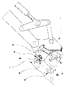
Figure 1 is a partially-sectioned schematic side view according
to line III-III of Figure 3;
Figure 2 is a side view of a detail shown Figure 1;

Figure 3 is a schematic side view from the left of the detail
shown in Figure 2;
Figure 4 is an exploded side view of the detail shown in Figure
2.

Detailed Description:
The invention will be described for the purposes of illustration
only in connection with certain embodiments; however, it is to be
understood that other objects and advantages of the present
invention will be made apparent by the following description of
the drawings according to the present invention. While the
preferred embodiment is disclosed, this is not intended to be
limiting. Rather, the general principles set forth herein are
considered to be merely illustrative of the scope of the present
invention and it is further understood that numerous changes may
be made without straying from the scope of the present invention.
With reference to the drawings, Figure 1 to 4 illustrates a body
1 of a rapid coupling device for digger tools, of the type in
which the tool 7 is provided with a first pivot shown as pin 3
and a second pivot shown as pin 4. The first pin 3 and the
second pin 4 together constitute means by which the tool will be
hooked up. The body 1 is provided with blocking devices
comprising mobile hooks 2 which achieve stable but removable
couplings with at least one of the two pins 3 and 4, and
especially with the second pin 4.

4


CA 02411759 2006-11-16

The hooking-up is achieved by coupling the pins 3 and 4 in
special coupling seatings 50 and 60 especially afforded in first
supports 5 and second supports 6 which are removably fixed on the
body 1. Each body 1 is predisposed to receive a pair of first

supports 5 and a pair of second supports 6. The supports of each
pair are positioned in such a way that the surfaces of the
seatings 50 and 60 are aligned to couple respectively with the
first pins 3 and the second pins 4. The first supports 5 and the
second supports 6 are mounted easily and removably on the body 1,
and can be constrained thereon in predetermined positions.
Furthermore, for each tool 7, i.e. for each hooking-up system
constituted by a first pin 3 and a second pin 4, a set formed by
a pair of first supports 5 and a pair of second supports 6 is
provided. Thus, by mounting the right supports 5 and 6 on the
body 1, the desired tool can be fixed thereon.

It is not certain that in each case the above-described
conditions will arise. It is possible that even with a plurality
of different tools 7, it will be necessary to have a
corresponding number of first supports 5 and only one second
support 6 - or vice versa. In this embodiment, the first pins 3
(or second pins 4) of a plurality of tools 7 are not very
different in type one from another. The pins 3 and 4 can be
coupled in a single seating 50 (or 60) of a first support 5 (or
second support 6), the same seating being suitable for all of the
tools 7, for situations where the geometrical and dimensional
difference in the attachment is present only in the seatings 60
(or 50) of the second supports 6 (or first supports 5).

More generally, there is a plurality of first supports 5 which
5


CA 02411759 2006-11-16

corresponds to a plurality of second supports 6. These supports 5
and 6 are predisposed to couple with a corresponding plurality of
the first pins 3 and the second pins 4, and can in all cases be
removably fixed to the body 1. The stability of the couplings is
ensured by the fact that a single pair, formed by a first pin 3
and a second pin 4 on a single tool 7, is coupled with another
pair constituted by first supports 5 and second supports 6.

The relative linkage between the first supports 5 and the body 1
is removable and uses a common reference on the body for all the
first supports S. The relative linkage between the second
supports 6 and the body 1 is removable and uses the same
references on the body for all the second supports 6.

In particular, the references are formed by holes 11 made on the
body 1 for allowing any first support 5 to be bolted thereon, and
by other holes 12, also made on the body 1 for allowing any
second support 6 to be bolted thereon.

The adaptation of the tool attachment to a specific tool 7 is
made easy by making the attachment itself as a modular structure
which comprises a body 1, provided with mobile hooks 2 which in
the illustrated embodiment are so moved by a pneumatic cylinder
8, and a double plurality of pairs of first supports 5 and second
supports 6 which are easily mountable on, and dismountable from,
the body 1.

A special combination of first supports 5 and second supports 6
corresponds to each tool. When mounted on the body 1, by using
the predetermined references, a rapid attachment can simply be
6


CA 02411759 2006-11-16

obtained simply, which corresponds to the particular coupling
dimensions of the single tool.

It should be understood that the preferred embodiments mentioned
here are merely illustrative of the present invention. Numerous
variations in design and use of the present invention may be
contemplated in view of the following claims without straying
from the intended scope and field of invention herein disclosed.
7

Representative Drawing
A single figure which represents the drawing illustrating the invention.
Administrative Status

For a clearer understanding of the status of the application/patent presented on this page, the site Disclaimer , as well as the definitions for Patent , Administrative Status , Maintenance Fee  and Payment History  should be consulted.

Administrative Status

Title Date
Forecasted Issue Date 2007-10-09
(22) Filed 2002-11-13
(41) Open to Public Inspection 2003-05-19
Examination Requested 2004-09-07
(45) Issued 2007-10-09
Deemed Expired 2008-11-13

Abandonment History

There is no abandonment history.

Payment History

Fee Type Anniversary Year Due Date Amount Paid Paid Date
Registration of a document - section 124 $100.00 2002-11-13
Application Fee $300.00 2002-11-13
Request for Examination $800.00 2004-09-07
Maintenance Fee - Application - New Act 2 2004-11-15 $100.00 2004-11-12
Maintenance Fee - Application - New Act 3 2005-11-14 $100.00 2005-09-29
Maintenance Fee - Application - New Act 4 2006-11-13 $100.00 2006-11-02
Final Fee $300.00 2007-07-24
Owners on Record

Note: Records showing the ownership history in alphabetical order.

Current Owners on Record
MANTOVANIBENNE S.R.L.
Past Owners on Record
MANTOVANI, ALBERTO
Past Owners that do not appear in the "Owners on Record" listing will appear in other documentation within the application.
Documents

To view selected files, please enter reCAPTCHA code :


To view images, click a link in the Document Description column. To download the documents, select one or more checkboxes in the first column and then click the "Download Selected in PDF format (Zip Archive)" or the "Download Selected as Single PDF" button.

List of published and non-published patent-specific documents on the CPD .

If you have any difficulty accessing content, you can call the Client Service Centre at 1-866-997-1936 or send them an e-mail at CIPO Client Service Centre.


Document
Description 
Date
(yyyy-mm-dd) 
Number of pages   Size of Image (KB) 
Abstract 2002-11-13 1 22
Description 2002-11-13 5 238
Claims 2002-11-13 2 70
Drawings 2002-11-13 3 61
Representative Drawing 2003-01-30 1 9
Cover Page 2003-04-25 1 35
Claims 2004-11-19 2 59
Description 2006-11-16 7 257
Claims 2006-11-16 2 66
Cover Page 2007-09-17 1 36
Prosecution-Amendment 2004-09-07 1 34
Assignment 2002-11-13 4 195
Prosecution-Amendment 2006-05-17 2 66
Prosecution-Amendment 2004-11-19 4 111
Prosecution-Amendment 2006-11-16 12 398
Correspondence 2007-07-24 2 48