Note: Descriptions are shown in the official language in which they were submitted.
CA 02411779 2002-11-13
OPTICAL FIBER COLLIMATOR USING GRADIENT INDEX ROD LENS
L
BACKGROUND OF THE INVENTION
The present invention relates to an optical fiber
collimator using a gradient index rod lens.
Fig. 1 shows a conventional collimator optical device
50 having incident side and receiving side optical fiber
collimators. The incident side optical fiber collimator
includes an optical fiber 11 and a rod lens L1, and the
receiving side optical fiber collimator includes an optical
fiber 12 and a rod lens L2. The optical device 50 converts
lights emitted from the single mode fiber 11 on the
incident side into collimated lights by use of the
collimator lens L1, and condenses the collimated lights by
use of the collimator lens L2 to couple them to the single
mode fiber 12 on the receiving side. The collimator lenses
L1 and L2 are gradient index rod lenses having a refractive
index distribution in a radial direction.
Various kinds of collimator optical devices (devices
for optical communications) 50 are produced by inserting an
optical function element (e.g., an optical filter, an
optical isolator, an optical switch or an optical
modulator) between the rod lenses L1 and L2. The device
for optical communications causes a predetermined function
to a light having propagated through the optical fiber 11
by use of the optical function element, and then couples
the light again to the optical fiber 12. In order to use a
function element (e. g., a large-sized matrix switch)
requiring a long light path length and having a large size
to cause the predetermined function, it is required to
provide a device for optical communications having as great
opposing distance (maximum collimation length Lmax) between
the rod lenses L1 and L2 as possible, and as high coupling
- 1 -
CA 02411779 2002-11-13
efficiency as possible.
Fig. 2 shows an optical fiber collimator 10 used in
the collimator optical device 50. The optical fiber
collimator 10 includes a gradient index rod lens 13, a
single mode fiber 14, a capillary 15 for holding the
optical fiber 14, and a glass tube 16. An incident side
-end face of the rod lens 13 and an end face of the optical
fiber 14 are each inclined planes obliquely buffed. The
rod lens 13 and the capillary 15 are fixed inside the glass
tube 16 at a position where the incident side end face of
the rod lens 13 and the end face of the optical fiber 14
are away from each other by a focal length of the rod lens
13.
In the optical fiber collimator 10, it is necessary to
- 15 increase the focal length of the rod lens I3 and enlarge a
beam diameter, in order to increase the opposing distance.
The focal length of the rod lens 13 can be changed by
adjusting a lens length Z of the rod lens 13. Here, the
"lens length" is the length between both the end faces of
the rod lens. In the case of the rod lens 13 having an
inclined plane, the "lens length" is the distance from an
intersection point of the inclined plane and a center axis
to the incident side end face (see Fig. 6). Since the
gradient index rod lens has a meandering period (pitch) of
a ray determined by its refractive index distribution, the
lens length Z is expressed. by pitch as a unit.
For example, in the case of a normal rod lens having a
lens element diameter of ~ 1.8 mm and a lens length Z of
0.25 pitches, the opposing distance is about 70 mm. On the
contrary, if the lens length is changed to 0.1 pitches, the
opposing distance extends up to about 200 mm. If the lens
length Z of the rod lens having a lens element diameter of
0.1 mm is changed from 0.25 pitches to 0.1 pitches, the
- 2 -
CA 02411779 2002-11-13
opposing distance extends from about 20 mm to about 70 mm.
In the conventional~optical fiber collimator 10, it is
necessary to decrease the lens length Z in order to
. increase the opposing distance. For example, if the lens
element diameter of the rod lens 13 is ~ I.8 mm and the
lens length Z thereof is 0.23 pitches, the actual lens
length Z is 4.8 mm. If the lens element diameter of the
lens 13 is ~ 1.8 mm and the lens length Z thereof is 0.1
pitches, the actual lens length Z is about 2 mm. Tf the
lens element diameter of the lens 23 is ~ 1.0 mm and the
lens length Z thereof is 0.1 pitches, the actual lens
length Z is 1.2 mm. However, if the lens length Z is small,
the following problems are caused.
(1) As shown in Fig. 3, if a short rod lens 13A
having a length of, for~example, 1.2 mm is set to the glass
tube 16, the rod lens 13A might incline because an axial
length of an outer circumferential surface (referential
surface) of the rod lens 13A is small. If the rod lens 13A
inclines, the collimated light (emitted light) emitted from
the rod lens 13A inclines with respect to the axial
direction, which decreases the coupling efficiency. As a
result, reliability might be decreased.
(2) If the length of the lens is small, it is
difficult to cut or buff the lens when the rod lens 13A is
manufactured. Especially, it is sometimes impossible to
obliquely buff the end face of the lens. This is because
it is difficult to hold the rod lens 13A in the cutting and
buffing processing.
_(3) It is difficult to handle the lens if the length
of the lens is small.
SUMMARY OF THE INVENTION
- 3 -
CA 02411779 2002-11-13
An object of the present invention is to provide an
optical fiber collimator~using a gradient index rod lens
that secures a required long opposing distance and is easy
to handle.
To attain the aforementioned .object, the present
invention provides an optical fiber collimator including: a
single mode fibers and a gradient index rod lens for
receiving an incident light from the single mode fiber and
converting the incident light into a collimated light, or
condensing an incident light and coupling the condensed
incident light to the single mode fiber. A meandering
period (pitch) of a ray determined by a refractive index
distribution of the rod lens is decided. The gradient.
index rod lens has a lens length larger by 0.5 meandering
periods than a minimum lens length required to obtain a
predetermined opposing distance between a pair of the rod
lenses.
Furthermore, the present invention provides a gradient
index rod lens optically coupled to an optical fiber. The
rod lens has a refractive index distribution for deciding a
meandering period (pitch) of a ray and a lens length larger
by 0.5 meandering periods than a minimum lens length
required to obtain a predetermined opposing distance
between a pair of the rod lenses.
Other aspects and advantages of the invention will
become apparent from the following description, taken in
conjunction with the accompanying drawings, illustrating by
way of example the principles of the invention.
BRIEF DESCRIPTION-OF THE DRAWINGS
The invention, together with objects and advantages
thereof, may best be understood by reference to the
following description of the presently preferred
- 4 -
CA 02411779 2002-11-13
embodiments together with the accompanying drawings in
which:
Fig. 1 is a schematic constitution view showing a
conventional collimator optical device;
Fig. 2 is a schematic sectional view of a conventional
optical fiber collimator;
Fig. 3 is a schematic sectional view of another
conventional optical fiber collimator;
Fig. 4 is a schematic sectional view of an optical
fiber collimator in accordance with a first embodiment of
the present invention;
Fig. 5 is a schematic sectional view of the
conventional optical fiber collimator including a rod lens
having a smaller lens length than a lens length of a rod
lens of the collimator of Fig. 4;
Fig. 6 is an enlarged view of the rod lens of the
optical fiber collimator of Fig. 4;
Fig: 7 is an explanatory view showing an imaging state
of the rod lens of 1/2 pitch; and
Fig. 8 is a schematic sectional view of the optical
fiber collimator in accordance with a modification.
DETAILED DESCRIPTION OF THE PREFERRED EMBODIMENTS
In the drawings, like numerals are used for like
elements throughout.
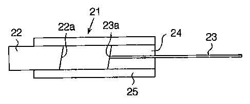
Fig. 4 is a schematic sectional view of an optical
fiber collimator 21 using a gradient index rod lens in
accordance with a first embodiment of the present invention..
The optical fiber collimator 21 includes a gradient index
.30 rod lens 22, a single mode fiber 23, a capillary 24 for
holding the optical fiber 23, and a glass tube 25. An
incident side end face 22a of the gradient index rod lens
(hereinafter referred to as a rod lens) 22 and an end face
5 -
CA 02411779 2002-11-13
23a of the optical fiber 23 are each inclined planes
obliquely buffed. The single mode fiber (hereinafter
referred to as an optical fiber) 23 is inserted into a
fiber insertion hole (not shown) of the capillary 24 and
integrated with the capillary 24 by use of an adhesive
agent. The rod lens 22 and the capillary 24 are fixed
inside the glass tube 25 by use of, for example, an
adhesive agent, at a position where the incident side end
face 22a of the rod lens 22 and the end face 23a of the
optical fiber 23 are away from each other by a focal length
of the rod lens 22.
Fig. 5 is a schematic sectional view of a conventional
optical fiber collimator 21A including a rod lens 42 having
a smaller lens length than the lens length of the rod lens
22. The constitution of the optical fiber collimator 21A
except for the rod lens 42 is the same as that of the
optical fiber collimator 21.
The lens element diameter of the rod lens 42 is ~ 1.0
mm, and its actual lens length Z is 1.2 mm. The opposing
distance of the rod lens 42 is about 70 mm.
The lens element diameter of the rod lens 22 is ~ 1.0
mm, and the actual lens length Z of the rod lens 22 is 7.2
mm (see Fig. 6). The lens length Z of the rod lens 22 is
larger than the lens length (minimum lens length) Z of the
rod lens 42 (e. g., 0.1 pitches) by 0.5 pitches (1/2
meandering periods). Therefore, the rod lens 22 makes it
possible to obtain an opposing distance of about 70 mm
equal to the opposing distance of the rod lens 42.
Fig. 7 shows the relation between a meandering period
(pitch) P of a ray and the lens length Z. Normally, when
the lens length Z of the gradient index rod lens is
increased by 1/2 pitches, an image is only inverted at both
- 6 -
CA 02411779 2002-11-13
ends having a length . of 1 /2 pitches ( P1 -~ Qi, P2 -~ 'Q2 : see
Fig. 7), but the magnification of the lens is not changed.
Therefore, the focal length of the lens is not changed.
r Owing to the characteristics of the gradient index rod lens,
the rod lens 22 makes it possible to obtain the same
opposing distance as that of the rod lens 42, and the rod
lens 22 can have a lens length Z about six times as large
as that of the rod lens 42.
Hereinafter, the characteristics of the gradient index
rod lens will be described using Equations.
When a distance in a radial direction from the center
of a section of the rod lens is r, a refractive index
distribution n (r) of the gradient index rod lens is
expressed by Equation (1) as follows:
n (r) - no (1 - Ar2/2) ~ ~ - (1)
In this case, a focal length f of the lens is
expressed by Equation (2) as follows:
f = 1/(no '~A ~ sin (~A ~ Z) ) ~ ~ ~ (2)
In Equations (1) and (2), no is the refractive index at the
center of the rod lens, '~A is a refractive index
distribution constant, and Z is the lens length. As
apparent from Equation (2), the facal length f changes
periodically with the lens length Z.
The meandering period (pitch) P of the lens is
expressed by Equation (3) as follows:
P = 2~c / ~A ... (3)
From Equations (2) and (3), the focal'length f has the
same value (absolute value)~on a period of P/2 (0.5
pitches), with respect to the lens length Z. That is, the
focal length f does not change even if the lens length Z is
increased by P/2, so that the same lens characteristics can
be obtained. In Equation (2), the sign of sin is inverted
CA 02411779 2002-11-13
every P/2 periods, and the image is inverted in accordance
with the inversion of the sign of sin.
A maximum collimator length Lmax is expressed by
Equation (4) as follows:
Lmax = 1 / { na'~A ~ tan ( VA ~ Z ) } - f ~ cos ( YA ~ Z )
... (4)
Therefore, the maximum collimator length Lmax changes
in the same period as that of the focal length f with
respect to the lens length Z.
The optical fiber collimator 21 in the first
embodiment has the following advantages.
(1) The lens length Z of the rod lens 22 is larger
than the lens length (minimum lens length) Z of the rod
lens 42 (0.1 pitches) by 0.5 pitches. Therefore, it is
possible to obtain the same opposing distance (about 70. mm)
as that of the rod lens 42, and it is possible to use the
rod lens 22 having a length of 7.2 mm, which is about six
times as large as that of the rod lens 42. In this way,
the required long opposing distance can be secured, and an
emitted light of the rod lens 22 can be prevented from
inclining with respect to the axial direction of the lens,
so that the coupling efficiency can be prevented from being
decreased. Therefore, it is possible to improve the
reliability while securing the required long opposing
distance.
(2) The lens length Z of the rod lens 22 is about six
times as large as that of the rod lens 42, so that it is
easy to handle the lens 22. Therefore, it is easy to hold
the lens 22 in the buffing processing of, for example,
cutting. or obliquely buffing the rod lens 22, thereby
facilitating the cutting or oblique buffing when the lens
22 is manufactured.
The gradient index rod lens used in the optical fiber
g _
CA 02411779 2002-11-13
collimator in accordance with a second embodiment of the
present invention has a lens diameter of ~ 1.8 mm and a
lens length Z of about 12 mm. The opposing distance of the
rod lens is about 200 mm. The lens length Z of the rod
lens in the second embodiment is larger by 0.5 pitches than
the lens length Z necessary to obtain an opposing distance
of about 200 mm (0.l pitches, about 2.0 mm).
The optical fiber collimator in the second embodiment
has the same advantages as the optical fiber collimator in
the first embodiment.
It should be apparent to those skilled in the art that
the present invention may be embodied in many other
specific forms without departing from the spirit or scope
of the invention. Particularly, it should be understood
that the invention may be embodied in the following forms.
- ~ In each embodiment, the minimum lens length
required to obtain the opposing distance, which is
increased by 0.5 pitches, is not limited to 0.1 pitches.
In short, the rod lens.may have a length increased by 0.5
pitches, with respect to the minimum lens length.
Preferably, the minimum lens length is 0.1 pitches or more.
~ The minimum lens length is preferably from about
0.7 or more to about 2 mm or less.
~ In each embodiment, the lens element diameter is
arbitrary.
~ In each embodiment, any of the following methods
may be applied as a "me-thod of increasing the lens length
(pitch) Z". (1) A method of cutting a rod lens to let it
have (0.1 + 0.5) pitches, out of a lens base material that
is the same as a rod lens having a small lens length Z, for
example, a rod lens of 0.1 pitches. (2) A method of
cutting a rod lens having a small lens length, for example,
a lens of 0.1 pitches,.to let it have 0.5 pitches, out of a
- 9 -
CA 02411779 2002-11-13
lens base metal having the same lens element diameter as a
lens of 0.1 pitches, and~then joining the cut rod lens to
the lens of 0.1 pitches.
~ The present invention can also be applied to an
optical fiber collimator 21B in which anti-reflection
measures are taken as shown in Fig. 8. Zn the optical.
fiber collimator 21B, anti-reflection films 31, 32 and 33
are formed on both end faces of the rod lens 22 and the end
face of the optical fiber 23, respectively.
Therefore, the present examples and embodiments are to
be considered as illustrative and not restrictive and the
invention is not to be limited to the details given herein,
but may be modified within the scope and equivalence of the
appended claims.
- 10 -