Language selection

Search

Patent 2411800 Summary

Third-party information liability

Some of the information on this Web page has been provided by external sources. The Government of Canada is not responsible for the accuracy, reliability or currency of the information supplied by external sources. Users wishing to rely upon this information should consult directly with the source of the information. Content provided by external sources is not subject to official languages, privacy and accessibility requirements.

Claims and Abstract availability

Any discrepancies in the text and image of the Claims and Abstract are due to differing posting times. Text of the Claims and Abstract are posted:

  • At the time the application is open to public inspection;
  • At the time of issue of the patent (grant).
(12) Patent: (11) CA 2411800
(54) English Title: ORBITAL SANDER WITH SUCTION RING
(54) French Title: PONCEUSE ORBITALE AVEC ANNEAU D'ASPIRATION
Status: Expired and beyond the Period of Reversal
Bibliographic Data
(51) International Patent Classification (IPC):
  • B24B 23/04 (2006.01)
  • B24B 23/03 (2006.01)
  • B24B 55/10 (2006.01)
(72) Inventors :
  • MARTON, MIKSA (Canada)
(73) Owners :
  • MIKSA MARTON
(71) Applicants :
  • MIKSA MARTON (Canada)
(74) Agent: R. WILLIAM WRAY & ASSOCIATES
(74) Associate agent:
(45) Issued: 2007-01-23
(22) Filed Date: 2002-11-13
(41) Open to Public Inspection: 2003-05-13
Examination requested: 2002-11-13
Availability of licence: N/A
Dedicated to the Public: N/A
(25) Language of filing: English

Patent Cooperation Treaty (PCT): No

(30) Application Priority Data:
Application No. Country/Territory Date
10/054,517 (United States of America) 2001-11-13

Abstracts

English Abstract


A rotary orbital sander includes a motor
having a rotatable shaft with a radially off-set
portion. A suction housing is mounted to the motor
around the motor shaft and connectable with a vacuum
source. A sanding pad assembly including a backing
pad having a plurality of apertures therethrough and
an annular frame having a circumferential side wall
including first and second circumferential edges is
mounted to the radially off-set portion of the shaft.
A circular back wall extends from one of the
circumferential edges and has an opening therein
sealable with the suction housing. The other
circumferential edge is attached to the backing pad.
The sanding pad assembly resists flapping at high
rotational speeds. A sanding disk having a size and
shape complimentary to that of the sanding pad, and a
plurality of holes aligning with the apertures in the
sanding pad is mountable on the sanding pad. A
vacuum source draws sanding waste through the aligned
apertures and out the suction housing.


Claims

Note: Claims are shown in the official language in which they were submitted.

CLAIMS
The embodiments of the invention in which an exclusive property or privilege
is
claimed are defined as follows:
1. A suction ring for an orbital sander including a motor having a
rotatable shaft with a radially off set portion, a suction housing mounted to
the motor
around the motor shaft and connectable with a vacuum source for supplying
vacuum
pressure around the shaft, and a sanding pad assembly having a plurality of
apertures
therethrough, said suction ring comprising:
an annular frame mountable on said rotatable shaft and adapted for
rotation therewith, said annular frame having a circumferential side wall
including first
and second circumferential axially spaced edges and disposed between said
suction
housing and said sanding pad assembly;
one of said edges defining an opening and adapted to mount to the
sanding pad assembly thereon, said edge being a lower edge of said side wall;
and
a circular back wall extending generally radially inward from the other
of said circumferential edges and having an opening therein for communicating
said
vacuum pressure from said suction housing through said suction ring to said
orbital
sanding pad assembly;
said back wall being continuous with the other of said circumferential
edges of said circumferential side wall;
whereby said sanding pad assembly is rotatably supported against
flapping by said rotating suction ring and sanding waste can be communicated
through
said plurality of apertures of said sanding pad and through said suction ring
to said
suction housing.
2. The suction ring of claim 1 further comprising:
a plurality of radially disposed ribs extending generally from said
circumferential side wall to a like plurality of leg members disposed about
said opening
in said circular back wall, stiffening said suction ring and sanding pad
assembly.

3. The suction ring of claim 1 wherein said ring is made generally of
aluminum material.
4. A rotary orbital sander, comprising:
a motor having a rotatable shaft with a radially off set portion;
a suction housing mounted to the motor, around said motor shaft and
connectable with a vacuum source,
a sanding pad assembly mounted to the radially off set portion of said
shaft and adapted for rotation therewith;
said sanding pad assembly further including a backing pad having a
plurality of apertures therethrough and an annular frame having a
circumferential side
wall including first and second circumferential axially spaced edges and
disposed
between said suction housing and said backing pad;
a circular back wall extending generally radially inward from one of said
circumferential edges and having an opening therein sealable with said suction
housing;
and
the other of said circumferential edges being attached to said backing
pad.
5. The rotary orbital sander of claim 4, including a plurality of radially
disposed ribs extending generally from said circumferential side wall to a
like plurality
of leg members disposed about said opening in said circular back wall,
stiffening said
sanding pad assembly and backing pad.
6. The rotary orbital sander of claim 4, wherein said sanding pad
assembly further includes a sanding disk having a size and shape complimentary
to said
sanding pad, and a plurality of holes for alignment with the said apertures in
said
backing pad.
7. A sanding pad assembly for use with a rotary orbital sander having a
suction housing connectable with a vacuum source for drawing out sanding
waste, said
sanding pad assembly comprising:

a backing pad having a periphery;
a plurality of apertures extending through said backing pad; and
an annular frame having a circumferential side wall including first and
second circumferential axially spaced edges, one of said edges being a lower
edge of
said side wall and being attached to said backing pad, and a back wall
extending
generally radially inward from the other of said circumferential edges and
having an
opening in vacuum pressure flow communication with said suction housing.
8. The sanding pad assembly of claim 7, further including a sanding disk
having a plurality of holes disposed in like fashion to said apertures in said
backing pad
so that the plurality of holes of the disk align with the apertures in the
backing pad.

Description

Note: Descriptions are shown in the official language in which they were submitted.


CA 02411800 2005-09-19
1
04004.003
ORBITAL SANDER WITH SUCTION RING
TECHNICAL FIELD
This invention relates to a rotary orbital
sander, and more particularly to a rotary orbital
sander that is adapted for use with a vacuum source.
BACKGROUND OF THE INVENTION
In U.S. Patent No. 6,413,157, I disclosed a
double action orbital sander having a sanding pad
including a plurality of radially extending suction
channels for drawing sanding waste through holes in a
sanding disk aligned with the annular channels.
Although this arrangement has been very effective for
collecting and transporting loosened particles to a
suction housing, I have improved upon the delivery of
vacuum pressure provided through the holes in the
sanding disk.
My earlier application also included a
unique balancing system that uniquely balanced a pad
backing and backing pad mounted on the rotatable
shaft and minimized flapping of the pad backing and
back up pad under the high rotational operational
speed of the pad, that may be in excess of 10,000
rpm. While improving delivery of vacuum presence, I
have further improved upon eliminating the flapping
associated with the high speed rotation of a large
diameter pad backing of a disk shape.

CA 02411800 2003-02-03
2
SUMMARY OF THE INVENTION
The present invention provides a suction
ring for an orbital sander and/or a rotary orbital
sander that improves upon the unobstructed flow of
vacuum pressure provided through holes in a backing
pad and sanding disk. In this way, the suction ring
increases the delivered vacuum pressure to the
sanding disk.
The present invention also provides a
suction ring that improves upon the elimination of
flapping associated with the high speed rotation of a
disk shaped pad backing and backing pad of relatively
large diameter by providing a bridge-like structure
that attaches to the backing pad to work as one piece
with the pad backup and backup pad.
The suction ring is provided for use with
an orbital sander including a motor having a
rotatable shaft with a radially off-set portion, a
suction housing mounted to the motor around the motor
shaft and connectable with a vacuum source for
supplying vacuum pressure around the shaft, and a
sanding pad assembly having a plurality of apertures
therethrough.
The suction ring includes an annular frame
having a circumferential side wall including first
and second circumferential edges. The suction ring
is disposed between the suction housing and the
sanding pad assembly. One of the edges defines an
opening and is adapted to mount to the sanding pad
assembly. A circular back wall having an opening
therein communicates the vacuum pressure from the

CA 02411800 2003-02-03
3
suction housing to the orbital sanding pad assembly.
The back wall is continuous with the other
circumferential edge of the circumferential side
wall. Sanding waste is communicated through the
5 sanding pad passageways and suction ring to the
suction housing. .
In one embodiment a plurality of radially
disposed ribs extends generally from the
circumferential side wall to a like plurality of leg
10 members disposed about the opening in the circular
back wall, forming a bridge-like structure attached
to the sanding pad assembly which includes a pad
backing and back up pad. The suction ring itself is
rigid and it stiffens the assembly against
15 deformations that can occur at high rotational
velocity, which is often about 10,000 rpm.
The ring may be made generally of metal or
high impact plastic, and aluminum is the preferred
material.
20 A rotary orbital sander of the invention
includes a motor having a rotatable shaft with a
radially off-set portion. A suction housing is
mounted to the motor around the motor shaft and
connectable with a vacuum source. A sanding pad
25 assembly is mounted to the radially off-set portion
of the shaft.
The sanding pad assembly further includes a
backing pad having a plurality of apertures
therethrough and an annular frame having a
30 circumferential side wall including first and second
circumferential edges and disposed between said
suction housing and the sanding pad assembly. A

i
ii I I
CA 02411800 2003-02-03
4
circular back wall extends from one of the
circumferential edges and has an opening therein
sealable with the suction housing. The other
circumferential edge is attached to the backing pad.
5 The sanding pad assembly further includes a
sanding disk having a size and shape complimentary to
that of the sanding pad, and a plurality of holes
aligning with the apertures in the sanding pad.
A sanding pad assembly for use with a
10 rotary orbital sander having a suction housing
connectable with a vacuum source for drawing out
sanding waste includes a backing pad having a
periphery, a plurality of apertures extending through
said backing pad, and an annular frame having a
15 circumferential side wall attached to said backing
pad and including a circumferential edge defining in
part a back wall having an opening in vacuum pressure
flow communication with said suction housing.
The sanding pad assembly can further
20 include a sanding disk having a plurality of holes
disposed in like fashion to the apertures in the
backing pad so that the plurality of holes of the
disk align with the apertures in the sanding pad
assembly.
25 These and other features and advantages of
the invention will be more fully understood from the
following detailed description of the invention taken
together with the accompanying drawings.
30 BRIEF DESCRIPTION OF THE DRAWINGS
In the drawings:

CA 02411800 2003-02-03
5
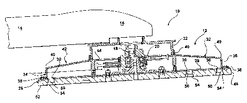
FIG. 1 is a cross-sectional view of a rotary
orbital sander constructed in accordance with the
present invention;
5
FIG. 2 is a cross-sectional view of a
suction housing illustrating a connector adapted for
connection with a vacuum source;
10 Fig. 3 is a schematic plan view, partially
in section, illustrating a sanding pad assembly of the
invention;
FIG. 4 is a sectional plan view of a suction
15 ring of the invention illustrating a plurality of
radially disposed ribs and like plurality of leg
members forming a bridge-like structure; and
FIG. 5 is a plan view of a sanding pad
20 illustrating the hole configuration therein and in the
pad backing.
DETAILED DESCRIPTION OF THE INVENTION
25
Referring now to the drawings in detail, a
rotary orbital sander is generally indicated by 10 and
includes a system 12 for communicating sanding waste
in accordance with the invention. Sander 10 includes
30 a handle 14 mounted to a drive motor 16. Motor 16 has
a rotatable shaft 18 with a radially off-set portion
20 extending generally perpendicular to the direction
of the handle 14. A suction housing 22 is mounted on
the motor 16 and the housing receives and surrounds
35 the rotatable shaft 18. Suction housing 22 is adapted

;f
CA 02411800 2003-02-03
6
to connect with a vacuum source, for example, a shop
vacuum, and includes a connector 24 for such
connection illustrated in FIG. 2.
A sanding pad assembly 26 is mounted for
5 rotation on the rotatable shaft 18. The sanding pad
assembly 26 includes a disk shaped pad backing 28 that
includes a plurality of apertures 30 through which
vacuum pressure is communicated. On a backside of pad
backing 28 there is attached a suction ring 32 for
10 rotation with the pad backing.
Suction ring 32 comprises an annular frame
34 having a circumferential side wall 36 including
first and second circumferential edges 38, 40.
Suction ring 32 is disposed between the suction
15 housing 22 and pad backing 28. One of the edges 38
defines an opening and is adapted to mount and/or
attach to the pad backing 28. A circular back wall 42
having an opening 44 therein communicates vacuum
pressure from the suction housing 22 to the apertures
20 in pad backing 28. The back wall 42 may be continuous
with circumferential edge 40 and the opening 44 is
spaced closely to the suction housing 22.
A seal ring 46, shown in phantom in FIG. 1
may be mounted around suction housing 22 adjacent the
25 suction ring opening 44 and lightly contact the
suction ring 32 to prevent false outside air from
getting into the flow of vacuum pressure which draws
loosened particles or sanding waste.
On the face of the pad backing 28 there is
30 mounted a resilient sanding pad 48 which. includes a
plurality of apertures 50 similarly disposed as the
apertures 30 in pad backing 28. Sanding pad 48
removably mounts a sanding disk 52 having abrasive
qualities and a like aperture 54 configuration as
35 apertures 30, 50. As particles are loosened during
the sanding process, they are drawn by the vacuum

CA 02411800 2003-02-03
7
source directly through aligned apertures 30, 50, 54,
into the suction ring 32 and out the suction housing
22.
In one embodiment, best seen in FIGS. 3 and
5 4, the suction ring 32 includes a plurality of
radially disposed ribs 56 that extend generally from
circumferential side wall 36 to a like plurality of
leg members 58 disposed about the opening 44 in the
circular back wall 42 forming a bridge-like structure.
10 In the illustrative embodiment, there are eight ribs
56 and eight leg members 58. The ribs 56 have a
section that extends perpendicular to the pad backing
28 and with the suction ring 32 mounted together with
'the sanding pad assembly 26 to act as one, the
15 assembly is greatly stiffened against possible
deformation at high rotational speeds.
Preferably, the suction ring 32 is made of
aluminum as is the pad backing 28. High impact
plastic construction may be used, but is less durable
20 in commercial applications.
Although the invention has been described by
reference to specific embodiments, it should be
understood that numerous changes may be made within
the spirit and scope of the inventive concepts
25 described. Accordingly, it is intended that the
invention not be limited to the described embodiments,
but that it have the full scope defined by the
language of the following claims.

Representative Drawing
A single figure which represents the drawing illustrating the invention.
Administrative Status

2024-08-01:As part of the Next Generation Patents (NGP) transition, the Canadian Patents Database (CPD) now contains a more detailed Event History, which replicates the Event Log of our new back-office solution.

Please note that "Inactive:" events refers to events no longer in use in our new back-office solution.

For a clearer understanding of the status of the application/patent presented on this page, the site Disclaimer , as well as the definitions for Patent , Event History , Maintenance Fee  and Payment History  should be consulted.

Event History

Description Date
Time Limit for Reversal Expired 2009-11-13
Letter Sent 2008-11-13
Grant by Issuance 2007-01-23
Inactive: Cover page published 2007-01-22
Inactive: Final fee received 2006-10-11
Small Entity Declaration Determined Compliant 2006-10-11
Pre-grant 2006-10-11
Notice of Allowance is Issued 2006-04-11
Letter Sent 2006-04-11
Notice of Allowance is Issued 2006-04-11
Inactive: Approved for allowance (AFA) 2006-03-22
Inactive: IPC from MCD 2006-03-12
Amendment Received - Voluntary Amendment 2005-09-19
Amendment Received - Voluntary Amendment 2005-05-12
Inactive: S.30(2) Rules - Examiner requisition 2005-03-17
Inactive: S.29 Rules - Examiner requisition 2005-03-17
Application Published (Open to Public Inspection) 2003-05-13
Inactive: Cover page published 2003-05-12
Inactive: Correspondence - Formalities 2003-02-03
Inactive: First IPC assigned 2003-01-30
Inactive: Filing certificate - RFE (English) 2003-01-10
Filing Requirements Determined Compliant 2003-01-10
Letter Sent 2003-01-10
Application Received - Regular National 2003-01-10
Request for Examination Requirements Determined Compliant 2002-11-13
All Requirements for Examination Determined Compliant 2002-11-13

Abandonment History

There is no abandonment history.

Maintenance Fee

The last payment was received on 2006-11-14

Note : If the full payment has not been received on or before the date indicated, a further fee may be required which may be one of the following

  • the reinstatement fee;
  • the late payment fee; or
  • additional fee to reverse deemed expiry.

Please refer to the CIPO Patent Fees web page to see all current fee amounts.

Fee History

Fee Type Anniversary Year Due Date Paid Date
Application fee - small 2002-11-13
Request for examination - small 2002-11-13
MF (application, 2nd anniv.) - small 02 2004-11-15 2004-11-15
MF (application, 3rd anniv.) - small 03 2005-11-14 2005-11-07
Final fee - small 2006-10-11
MF (application, 4th anniv.) - small 04 2006-11-14 2006-11-14
MF (patent, 5th anniv.) - small 2007-11-13 2007-11-13
Owners on Record

Note: Records showing the ownership history in alphabetical order.

Current Owners on Record
MIKSA MARTON
Past Owners on Record
None
Past Owners that do not appear in the "Owners on Record" listing will appear in other documentation within the application.
Documents

To view selected files, please enter reCAPTCHA code :


To view images, click a link in the Document Description column. To download the documents, select one or more checkboxes in the first column and then click the "Download Selected in PDF format (Zip Archive)" or the "Download Selected as Single PDF" button.

List of published and non-published patent-specific documents on the CPD .

If you have any difficulty accessing content, you can call the Client Service Centre at 1-866-997-1936 or send them an e-mail at CIPO Client Service Centre.


Document
Description 
Date
(yyyy-mm-dd) 
Number of pages   Size of Image (KB) 
Abstract 2002-11-13 1 37
Description 2002-11-13 7 321
Claims 2002-11-13 4 135
Drawings 2002-11-13 4 125
Representative drawing 2003-02-06 1 16
Cover Page 2003-04-22 1 49
Description 2003-02-03 7 251
Abstract 2003-02-03 1 29
Claims 2003-02-03 4 101
Drawings 2003-02-03 4 88
Claims 2005-09-19 3 107
Description 2005-09-19 7 251
Representative drawing 2007-01-03 1 14
Cover Page 2007-01-03 1 49
Acknowledgement of Request for Examination 2003-01-10 1 174
Filing Certificate (English) 2003-01-10 1 159
Reminder of maintenance fee due 2004-07-14 1 110
Commissioner's Notice - Application Found Allowable 2006-04-11 1 162
Maintenance Fee Notice 2008-12-29 1 171
Correspondence 2003-01-10 1 18
Correspondence 2003-02-03 17 487
Fees 2004-11-15 1 33
Fees 2005-11-07 1 31
Correspondence 2006-10-11 1 39
Fees 2006-11-14 1 37
Fees 2007-11-13 1 37