Note: Descriptions are shown in the official language in which they were submitted.
CA 02412083 2002-11-15
LOW EXTERNAL FIELD INDUCTOR
TECHNICAL FTELD OF THE INVENTION
The present invention is directed, in general, to
winding configurations for inductive devices and, more
specifically, to a winding configuration for an inductor
reducing or minimizing external magnetic fields.
BACKGROUND OF THE INVENTION
Many configurations for the windings of an inductor
around a core or form have been proposed or employed. The
simplest and most common configuration involves progressive
windings around the radial circumference of a cylindrical
core or form. Alternative configurations, usually designed
to maximize magnetic flux and/or inductance, increase
sensitivity to electromagnetic waves, or reduce Lorentz
forces, include toroidal windings (progressive windings
around a doughnut-shaped core or form) and similar
variations.
Tn borehole production, inductors are employed for
filtering electric (normally three phase) power to be
transmitted into the borehole. Surface voltage magnitudes
- 1 -
' CA 02412083 2002-11-15
of the electric power may equal or exceed 10 kilovolts
(kV), with associated, proportionally high currents. For
inductors having conventional configurations, such high
currents through the windings can produce intense magnetic
fields external to the inductor. The external magnetic
fields, in turn, induce eddy currents within surrounding
metals and conductors and, because of resistance, generate
undesirable heat. As a result, cabinets for enclosing
surface power equipment for borehole production systems
must be made larger to provide extra distance so that the
intense magnetic fields produced by the inductor do not
produce significant eddy currents within the cabinet walls.
There is, therefore, a need in the art for a low
external field inductor for use with borehole production
electric power systems.
- 2 -
' CA 02412083 2002-11-15
SUL~iARY OF THE INVENTION
To address the above-discussed deficiencies of the
prior art, it is a primary object of the present invention
to provide, for use in borehole production system, an
inductor which is wound axially around a cylindrical center
structure, such as a core or form, so that each turn
includes portions extending axially along a circumferential
outer surface of the center structure and portions
extending across the end surfaces of the center structure.
Adjacent axial portions, which are preferably but not
necessarily consecutive turns, carry current in the same
direction to the extent possible. External magnetic fields
therefore fall off rapidly and at least partially offset so
that, the inductor can handle high currents such as those
relating to filtered electric power transmitted into a
borehole for powering artificial lift equipment.
The foregoing has outlined rather broadly the features
and technical advantages of the present invention so that
those skilled in the art may better understand the detailed
description of the invention that follows. Additional
features and advantages of the invention will be described
hereinafter that form the subject of the claims of the
invention. Those skilled in the art will appreciate that
- 3 -
._.. _.x ~ , ~,~~f.,,~~:_~~~,~,p,~r ":,~u~a~,~"~~._...___.._______ _ _.
_.e_.__.__. ___._T..____
CA 02412083 2002-11-15
they may readily use the conception and the specific
embodiment disclosed as a basis for modifying or designing
other structures for carrying out the same purposes of the
present invention. Those skilled in the art will also
realize that such equivalent constructions do not depart
from the spirit and scope of the invention in its broadest
form.
Before undertaking the DETAILED DESCRIPTION OF THE
INVENTION below, it may be advantageous to set forth
definitions of certain words or phrases used throughout
this patent document: the terms "include" and "comprise,"
as well as derivatives thereof, mean inclusion without
limitation; the term "or" is inclusive, meaning and/or; the
phrases "associated with" and "associated therewith," as
well as derivatives thereof, may mean to include, be
included within, interconnect with, contain, be contained
within, connect to or with, couple to or with, be
communicable with, cooperate with, interleave, juxtapose,
be proximate to, be bound to or with, have, have a property
of, or the like; and the term "controller" means any
device, system or part thereof that controls at least one
operation, whether such a device is implemented in
hardware, firmware, software or some combination of at
least two of the same. It should be noted that the
- 4 -
..,.:..... ,..,. ..<,.."._ ~ ~ .,, .. w mr .... "u~,wuu.,_......,
.s.,ny"cmemaw-", .-x,:rraaumc~" _~:~fr n~,nm~n..:.:~,.
,o",:.."~"",..wws.",~..~....,.~,...""~.,~."" . _......f ...,.. ....._...,.. _
,......._... _.....__.._....._ ... ......
CA 02412083 2002-11-15
functionality associated with any particular controller may
be centralized or distributed, whether locally or remotely.
Definitions for certain words and phrases are provided
throughout this patent document, and those of ordinary
skill in the art will understand that such definitions
apply in many, if not most, instances to prior as well as
future uses of such defined words and phrases.
- 5 -
CA 02412083 2002-11-15
BRIEF DESCRIPTION OF THE DRAWINGS
For a more complete understanding of the present
invention, and the advantages thereof, reference is now
made to the following descriptions taken in conjunction
with the accompanying drawings, wherein like numbers
designate like objects, and in which:
FIGURE 1 depicts a borehole production system
employing a low external field inductor for filtering a
drive transmitting power into the borehole according to one
embodiment of the present invention;
FIGURES 2A through 2C are circuit diagrams for
suitable filter configurations including low external field
inductors for use in the electric power structure of a
borehole production system according to various embodiments
of the present invention;
FIGURES 3A through 3C are various views of the
windings of a low external field inductor according to one
embodiment of the present invention;
FIGURES 4 through 6 are various plots of the magnetic
field produced by a low external field inductor according
to one embodiment of the present invention; and
- 6 -
CA 02412083 2002-11-15
FIGURES 7 and 8 are end views of alternative winding
configurations for a low external field inductor according
to one embodiment of the present invention.
CA 02412083 2002-11-15
DETAILED DESCRIPTION OF THE INVENTION
FIGURES 1 through 8, discussed below, and the various
embodiments used to describe the principles of the present
invention in this patent document are by way of
illustration only and should not be construed in any way to
limit the scope of the invention. Those skilled in the art
will understand that the principles of the present
invention may be implemented in any suitably arranged
device.
FIGURE 1 depicts a borehole production system
employing a low external field inductor for filtering a
drive transmitting power into the borehole according to one
embodiment of the present invention. Production system 100
includes a power source 101, such as a generator or a
connection to the local alternating current (A/C) power
grid, coupled by power electronics 102 to an electrical
drive 103, which in the exemplary embodiment is preferably
a variable frequency drive (VFD) capable of operating in
one or more of an n-step variable voltage inverter (VVI)
mode and a pulse width modulation (PWM) mode.
Drive 103, under operational control of an associated
controller 104, generates electrical power (typically three
phase power) which is passed through resistive-capacitive
_ g _
CA 02412083 2002-11-15
(RC) filters) 105, which typically include series-, Y-, or
delta-connected capacitors) and inductor(s), then trans-
mitted over power cables) 106 into a borehole 107. The
transmitted power is received within the borehole 107 by
artificial lift equipment 108 coupled to production tubing
109 and lowered within the borehole 107 in accordance with
the known art. Those skilled in the art will recognize
that artificial lift equipment 108, which in the exemplary
embodiment preferably comprises an induction motor and a
submersible centrifugal pump forming an electrical
submersible pump (ESP) system, operates in response to the
received power to assist in production of oil, gas, and
other hydrocarbon fluids from the borehole 107. A detailed
description of the construction and operation of a suitable
electrical submersible pump system is contained in U.S.
Patent 6,167,965, issued to the assignee of the present
invention.
Those skilled in the art will recognize that the
complete construction and operation of a borehole
production system is not depicted or described herein.
Instead, only so much of the borehole production system as
is unique to the present invention or necessary for an
understanding of the present invention is shown and
described. However, borehole production system 100
- 9 -
' CA 02412083 2002-11-15
includes, embodied chiefly within filters) 105, one or
more low external field inductors according to the present
invention as described in greater detail below.
FIGURES 2A through 2C are circuit diagrams for
suitable filter configurations including low external field
inductors for use in the electric power structure of a
borehole production system according to various embodiments
of the present invention. Series-, Y-, and delta-connected
filters are respectively depicted. In the present
invention, each of the inductors LA, LB and L~ are
preferably low external field inductors as described below.
Moreover, those skilled in the art will recognize that such
low external field inductors may be employed at other
locations within the electric power structure of a borehole
production system, such as in filters for taps to the power
cable conductors within the borehole.
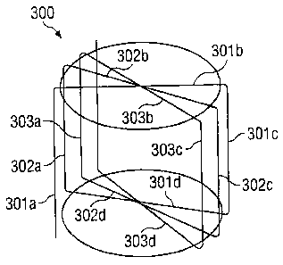
FIGURES 3A through 3C are various views of the
windings of a low, external field inductor according to one
embodiment of the present invention. FIGURE 3A is a
perspective view of a partially wound inductor 300. As
with conventional inductors, a cylindrical or drum-shaped
core or form is employed for low external field inductor
300. However, windings on a conventional inductor are
around a radial circumference of the core or form and
- 10 -
~>.:.~~~x:;ac.~w~a~nuu.,.~..mxmww..~..e..,.".,~..,...,~".w.~ ._ ,......"".",
.",.~.~..."~,n.....
' CA 02412083 2002-11-15
progress axially, forming a helix. Windings on low
external field inductor 300, however, are directed axially
and progress radially (on both sides) around the circum-
ferential outer surface of the core or form.
On inductor 300, a first winding or turn includes: a
portion 301a extending axially along the circumferential
outer surface of the core or form; a second portion 301b
extending diagonally across one end surface of the
cylindrical core or form; a third portion 301c also
extending axially along the circumferential outer surface
of the core or form, but on the side opposite portion 301a;
and a fourth portion 301d extending diagonally across a
second end surface of the cylindrical core or form. The
second and third turns similarly include portions 302a-203d
and 303a-303d, respectively, with axial portions 302a and
302c of the second turn each advanced in a clockwise
direction (viewed from the top end) around the circum-
ferential outer surface from corresponding axial portions
301a and 301c of the first turn, and axial portions 303a
and 303c of the third turn each advanced in a clockwise
direction around the circumferential outer surface from
corresponding axial portions 302a and 302c of the second
turn.
- 11 -
CA 02412083 2002-11-15
Each diagonal end portion of a turn crosses over the
corresponding diagonal end portions of all previous turns,
with end portions 302b and 302d crossing over end portions
301b and 301d, respectively, end portion 303b crossing over
both end portions 301b and 302b, and end portion 303d
crossing over both end portions 301d and 302d. In this
manner, axial portions of a turn advance from the previous
turn in the same direction around the circumferential outer
surface of the core or form on both sides. While the axial
portions of the turns progress clockwise (viewed from the
top end) in the example shown, counterclockwise progress is
equally suitable.
The windings are continued around the core or form in
the manner shown until the desired number of windings for
inductor 300 are complete. The axial portions of
successive turns may be directly adjacent and touching on
each side, or may be (preferably uniformly) spaced apart
around the circumferential outer surface of the core or
form.
FIGURES 3B and 3C are an end view and a side elevation
view, respectively, of a completely wound low external
field inductor 301 according to one embodiment of the
present invention. Inductor 301 has twenty uniformly
spaced turns, identified numerically, with arrowheads
- 12 -
~,u,.e., ".."... ...r," w , . ,"A4 fv..77x t%... ,m. .7FYMbfJveH.
.HaSHStaw~i~<.,ms,svdmHp»Hyu . ...nqvovmw~.~N....,~,<...M--.~.-. , ... .._....
CA 02412083 2002-11-15
indicating the direction of current flow within the
respective turn. As can be seen from FIGURE 3C, current
flows in same direction within adjacent axial portions of
the winding pairs (with the exception of the winding pair
containing the first and last turn). For those adjacent
winding pairs for which current flows in the same
direction, the resulting external magnetic fields will fall
off rapidly with distance from a given axial turn portion
and will also at least partially offset. Internal magnetic
fields also partially offset, but will accumulate somewhat
and therefore remain sufficiently strong to produce an
inductance due to the concentration over a smaller area.
Inductor 301 can handle high currents without creating
an intense external magnetic field, and does not
appreciably affect, nor is appreciably affected by,
ferromagnetic material in close proximity. Useful for
power systems, one application of inductor.301 is air core
inductors for pulse width modulated (PWM) output filters on
power system inverters. Another suitable use is high
quality (Q) inductors for radio frequency (RF) signals,
providing an inductor minimally affected by surrounding as
well as minimizing radiation. While an air core is
suggested for the exemplary embodiment, a high permeability
- 13 -
CA 02412083 2002-11-15
core may be employed to produce higher inductance per unit
volume.
FIGURES 4 through 6 are various plots of the magnetic
field produced by a low external field inductor according
to one embodiment of the present invention. The diagrams
relate to the magnetic field of inductor 301 depicted in
FTGURES 3B and 3C, taken at a section A-A at an arbitrary
position along the axial length of inductor 301. FIGURE 4
is a three dimension plot of magnetic field intensity as a
function of distance from the axis of inductor 301, while
FIGURE 5 is a vector view of the magnetic field and FIGURE
6 is a contour map of magnetic field intensity.
Referring back to FIGURES 3B and 3C, inductance for
inductor 301 may be calculated from:
n n
L = '~° nd 1 + 2~ cos 2'~ k In h + '~° nh 1 + 2~ cos 2~ k In
d'
' xm ~ n ~ 2~d . ?c n 2~d
k-,
w
where L is the inductance, = 4~z x 10-' v°lt ~ sec
,u° , n is the number
amp~m
of complete turns or loops, d~ is the cylinder diameter, h
is the cylinder height, and dw is the wire diameter. For a
cylinder having equal diameter and height of 1.13 inches
and wound 68 complete turns in the manner of inductors 300
- 14 -
CA 02412083 2002-11-15
and 301 with wire having a diameter of 0.027 inches, the
inductance will be approximately 103.19 micro-Henrys (uH).
Those skilled in the art will recognize that, for use
in filters) 105, the desired inductance of inductor 301
will vary inversely with the magnitude of electric power
being transmitted into the borehole. For example, for
1,000 kilo-volt-amps (kVA), a 40 mH inductor might be
required; for 500 kVA, an 80 mH inductor; and for 250 mH, a
160 mH inductor. Specific values will depend on other
system particulars.
FIGURES 7 and 8 are end views of alternative winding
configurations for a low external field inductor according
to one embodiment of the present invention. As with FIGURE
3B, the twenty turns are numerically identified and
arrowheads indicate the direction of current flow.
Variations in the winding configuration illustrated by
inductor 301 may be desirable or necessary for physical
reasons or for ease in manufacture. FIGURE 7 illustrates
that adjacent turns (along the axial length) need not
necessarily be consecutive turns. One or more consecutive
turns may be wound adjacent to each other, then a space
skipped before another set of adjacent, consecutive turns,
with the intervening gap filled by later turns. However,
the winding is again conffigured so that current in adjacent
- 15 -
CA 02412083 2002-11-15
axial portions of the turns is in the same direction to the
extent possible. Inductor 700 illustrates groups of three
turns, although the same technique may be employed with
single turns or groups of any number of turns.
FIGURE 8 illustrates that the inductor need not
necessarily be wound so that axial portions of turns
carrying current in the same direction are all adj acent, to
the extent possible, as with inductors 301 and 700.
Inductor 800 illustrates two spaced groups of three turns
having axial portions carrying current in the same
direction, separated by a group of three turns having axial
portions carrying current in the opposite direction. The
number and spacing of turns having adjacent axial portions
carrying current in the same direction may be varied, as
long as at least two adj acent axial portions carry current
in the same direction to reduce external magnetic fields.
It should be noted that the core or form need not be
perfectly cylindrical, but may instead have, for example,
an octagonal cross-section. End portions of the core or
form may be rounded, or may include guides for the winding
portions across the ends.
Although the present invention has been described in
detail, those skilled in the art will understand that
various changes, substitutions, variations, enhancements,
- 16 -
CA 02412083 2002-11-15
nuances, gradations, lesser forms, alterations, revisions,
improvements and knock-offs of the invention disclosed
herein may be made without departing from the spirit and
scope of the invention in its broadest form.
- 17 -
~, .. . . ~ ..