Language selection

Search

Patent 2412104 Summary

Third-party information liability

Some of the information on this Web page has been provided by external sources. The Government of Canada is not responsible for the accuracy, reliability or currency of the information supplied by external sources. Users wishing to rely upon this information should consult directly with the source of the information. Content provided by external sources is not subject to official languages, privacy and accessibility requirements.

Claims and Abstract availability

Any discrepancies in the text and image of the Claims and Abstract are due to differing posting times. Text of the Claims and Abstract are posted:

  • At the time the application is open to public inspection;
  • At the time of issue of the patent (grant).
(12) Patent: (11) CA 2412104
(54) English Title: TABULAR WORKPIECE NOTCHING MACHINE USABLE FOR GENERAL GRINDING OPERATIONS
(54) French Title: MACHINE A GRUGER POUR TRAVAUX GENERAUX D'ABRASION DE PIECES TUBULAIRES
Status: Expired and beyond the Period of Reversal
Bibliographic Data
(51) International Patent Classification (IPC):
  • B24B 7/00 (2006.01)
  • B24B 9/00 (2006.01)
  • B24B 21/00 (2006.01)
  • B24B 21/18 (2006.01)
  • B24B 41/00 (2006.01)
(72) Inventors :
  • CAPORUSSO, ALESSANDRO (Italy)
(73) Owners :
  • NEW TECH S.R.L.
(71) Applicants :
  • NEW TECH S.R.L. (Italy)
(74) Agent: GOWLING WLG (CANADA) LLP
(74) Associate agent:
(45) Issued: 2005-07-12
(22) Filed Date: 2002-11-14
(41) Open to Public Inspection: 2003-05-15
Examination requested: 2002-11-14
Availability of licence: N/A
Dedicated to the Public: N/A
(25) Language of filing: English

Patent Cooperation Treaty (PCT): No

(30) Application Priority Data:
Application No. Country/Territory Date
RM2001A000677 (Italy) 2001-11-15

Abstracts

English Abstract


A tubular workpiece notching machine usable for general grinding operations
has a worktable (1) whose base plate (10) is pivotally mounted to the frame
(6) of the notching machine around a pivotal orthogonal axis (Y-Y) in such a
manner that the worktable (1) is movable from a first working position in
which the machine vice (2) co-operates with the shaping pulley (3) in
recessing ends of tubular workpiece by grinding, to a second working
position in which the shaping pulley (3) is used for generally grinding a
workpiece. Connecting means are provided for removably anchoring the base
plate (10) of the worktable (1) to the frame (6) in the first working
position.


Claims

Note: Claims are shown in the official language in which they were submitted.

6
CLAIMS
1. A tubular workpiece notching machine usable for general grinding
operations, having on a frame (6) a pair of pulleys carrying an abrasive bell
(5) travelling endlessly on them, and a worktable (1) holding, up, over a base
plate (10), a machine vice (2) adjustable in its angular position with respect
to
a shaping pulley (3) of said pair of pulleys, characterized in that:
- said base plate (10) of the worktable (1) is pivotally mounted in said
frame (6) around a pivotal orthogonal axis (Y-Y) in such a manner that
the worktable (1) is movable, by rotation around said pivotal axis, from a
first working position in which the machine vice (2) co-operates with said
shaping pulley (3) in recessing ends of tubular workpiece by grinding, to
a second working position in which the shaping pulley (3) is used for
generally grinding a workpiece;
- connecting means are provided for removably anchoring said base plate
(10) of the worktable (1) to the frame (6) in said first working position.
2. The tubular workpiece notching machine according to claim 1,
characterized in that said pivotal axis (Y-Y) of the base plate (10) in the
frame (6) is made by a couple of lugs (60, 60) integral with the frame (6),
that
pivotally hold internally said base plate (10) through a rotational pivot (7).
3. The tubular workpiece notching machine according to claim 1,
characterized in that said connecting means for removably anchoring said
base plate (10) of the worktable (1) to the frame (6) in said first working
position comprise an abutting vertical plate (61) integral with the frame (6),
a
connecting counter-plate (11), which is connected at right angles to the base
plate (10) and designed to match frontally with said abutting vertical plate

7
(61) in said second working position, and threaded coupling means to
connect the abutting vertical plate (61) to the connecting counter-plate (11).
4. The tubular workpiece notching machine according to claim 3,
characterized in that said connecting means have male-female type, mutually
matching means (62, 12).
5. The tubular workpiece notching machine according to claim 1,
characterized in that said worktable is provided with a single hand control
member (8) for moving the machine vice (2) towards and away from the
shaping pulley (3) in said first working position.

Description

Note: Descriptions are shown in the official language in which they were submitted.


, .s
CA 02412104 2002-11-14
[.)PCCrIDtiOli
TuL~ular workgiece ncot~lticmmachitic usa.hle for ~t 4~ral
arindiug_nper~tio~~S
Tcchnxcal Field
''his invention relates to a tubular workPiecc nUtching machine usable
kar general grinding; ogErations. The term "grinding ogc;ration" means any
operation ~,vhich is pErformcd by removing chips from a workpiece by means
of an abrasive belt.
The so called notching machine is a grinding machine far shaping or
recessing the ands of tubular workpic,ccs- This zz~achine has a pair of
pulleys
carrying on an abrasive belt: one of the .pulleys is a dri~ring pulley for the
abrasive belt and the other puilsy is a shaping pulley co-operating with the
at~rasive belt to sliapa recesses. A machine vice .for clannpin~ a tubular
workpiece is located near the shaping pulley and is movable towards and
away from the shaping pulley in ardGr to allow the; tubular workpiecem
claci~ped by the machine vice, to be ground.
Back round of the Invention
In prior art notching machines, in ard~t to achiove a movement o1: tl~e
machinE vice towards and away from tll~ shaping pulley, the machine vice is
mounted so to rotate on a worktable as well known. 'The worktable has a
feeding xnovemeittt with respect to the shaping pulley, that is performed by
known feeding moans aad controlled by control means, that are known as
well.
l~ouradays natchitag machines ors trot able to operate as simple
grinding ~naachan~s because the ~xrorktable itself prevents an opcrxtor from

CA 02412104 2002-11-14
7
cringing workpiec:es to be ground gear the sltaning pulley. Therefore, today
twc~ diffiersnt nzachinec are r~quirGd in order to perform eit9zer t~;rindin~
8nd
notching operatioris_ 'This causes larks capital requirement;; with ~t
consequence of art increase of production cost;, a5 wrcil as a great
encumbrance in a plant.
This invention seeks to overcome the drawbacks above mentioned,
In particular, an objeck of the preaent invenkiott is to me.nufacture a
machine which allows bath tubular workpieces notehlng and genCral grinding
operations to b~ performed.
to l7isc osure of the Invention
Therefore, aceord.ing to the prnsEnt invention this object is achieved
by a tubular workpiece n4tching txsa.chine usable far general grinding
opcrat:ionso hawing on a frame a pair of pulleys carrying an abrasive belt
travelling endlessly on them, and a worktable holding up, over a base place, a
'15 machine vice adjustable in its ailgular position with respect to d shaping
pulley of said pair of pulleys, wherein said base plate of the warktablc is
pivotally mounted in said frame around a pivat;al orthogonal axis i11 Such a
rnanner iixat tht worktable is movable, by rotation around said pivotal axis,
from a first working position in which the machine vice co-operates with Said
20 shaping pulley in recessing ends of tubular workpiece by grinding, to a
second working positron in which the shaping pulley is used for generally
grinding a worlGgicce; connecting means being provided for removably
anchoring said base plate of the worktable to the frame in said first working
position.

CA 02412104 2002-11-14
3
'fhv invention will toe descxibe:d bElow with rel'ere;nce to an
cmhodizrient thereof in canncction with tl,c ac.ccmp.inyfn~, drawing, in
which;
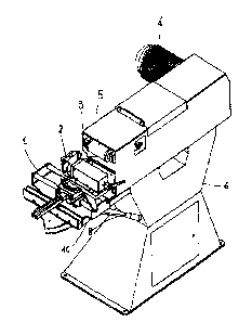
1=figure 1 is a perspective view of a notching machino according to the
present inve~ition in a working position Lor recessing ends of tubular
worklai.cces; and
Figure ~ is a pe:rspectivt; View al' ~2 tzotc:l2ittg machine in Flburc; 1 in a
wrorking position far general grinding operations.
In the figures a notching machine pulley according to the present
invention is shown. First, reference is made to Figure 1, in which a worktable
l0 1 holds up, over a base plate 10, a machine vice 2 adjustable in its
angular
po3ition with respect to a shaping pulley 3. The shaping pulley 3 i~ the title
pulley of a pair of pulleys, the otlacr pulley, not shown in the drawing,
being a
driving pulley connected to a motor 4. An ak~rasive belt S travels endlessly
on
the two pulleys.
The specific worktable 1, shown in the figur~s, is disclosed in another
patent application of the same Applicant. This worktable 1 i5 provided with a
single hand control member 8 for moving the machine vice 2 towards and
away from the shaping pulley 3,
Anyway, it should be apparent that the worktable could he difi'erent,
e.g. of a eonventlonal type. As known, the worktable allours the woxkpiacc
clamped by the machine vice 2 to be moved a~COxding to a desired
orientation anglo with respect to the shaping pulley 3.
Unusually the base plate ~.0 of tho wrorktable 1 is not integral with a
frame 6 if the notching machine. According to the present invention, as

CA 02412104 2002-11-14
SIIOVJn 11Z Figure 2, the bnsc l~laetc t0 i~ pivotally mautLted icl tl7e frame
h
around a pivotal orthogonal axis Y-Y.
In particular, in the delaicted embodilrient, the nivolrll axis Y-Y of the
bast plate 1() in the firame L5 is made by a couple of lugs 6(), (i(1 integral
uvith
s the l:rame 6, that pivotally hold internally the base plate 1(f thrnugl2 d
rot~.tionul pivot 7. Obviously, th4 pivotal axis can be made dilferettlly.
In this way the worktable 1 is movable, by rotation around the laivotal
axis ~f-Y, from a first wor>cing position shown in Figure 1 to a second
working position shown in Figure 2. In the first working position the machine
t o vice 2 co-operates with the shaping pulley 3 in recessing ends of tubular
workpiece (nor shown) by grinding, and in the second working position the
shaping ptLllcy 3 can lee used for generally grinding a workpicce. In this
second working position the worktable can be suitable joined to the frame of,
the machine.
is Even if not shown in Figure 2, the frame 6 can be provided with
useful fittings, for cxacnple a balancing platform, for grinding operdlions_
For
this purpose a front plate 62, being integral with the frame fi, can be used.
The front plate 61 operates as an abutting vertical plate for connecting means
adapted to removaf3ly anchor the base plate 10 of the worktable 1 to the
2o frame 6 in the first working p~sition.
Such connecting tnsans comprise, in addition to the vertical plate fix ,
a oonnocting counter-plate 11, which is connected at right angles to the base
plate a 0. Threaded coupling means, not shown, connect the vertical abutting
plate 61 to the connecting counter-plate 11, when the worktable is rotated
is from the second warlcing position to the first one.
"..o

CA 02412104 2002-11-14
Further, tile conneecing m4ans have tn~lc-female Type, txtutUttlly
matci~in~~ mans. For example such matching means err. mfide 1~y a list ft?
integrrtl in a lower hart of the abutting vertical plate (~1 rind a
correcpondin~;
slot 12 in the connecting counter-plate I1.
The present invention has been described with reference to its spccil:ic
embodiment, but it would be Expressly ttnderstttod that modifications,
addition and/or omissions can be made ouithout daparting from the Spirit o~
intretttion as defined in the Eaclnsed claims_

Representative Drawing
A single figure which represents the drawing illustrating the invention.
Administrative Status

2024-08-01:As part of the Next Generation Patents (NGP) transition, the Canadian Patents Database (CPD) now contains a more detailed Event History, which replicates the Event Log of our new back-office solution.

Please note that "Inactive:" events refers to events no longer in use in our new back-office solution.

For a clearer understanding of the status of the application/patent presented on this page, the site Disclaimer , as well as the definitions for Patent , Event History , Maintenance Fee  and Payment History  should be consulted.

Event History

Description Date
Time Limit for Reversal Expired 2011-11-14
Letter Sent 2010-11-15
Inactive: IPC from MCD 2006-03-12
Grant by Issuance 2005-07-12
Inactive: Cover page published 2005-07-11
Pre-grant 2005-04-25
Inactive: Final fee received 2005-04-25
Notice of Allowance is Issued 2005-03-10
Letter Sent 2005-03-10
Notice of Allowance is Issued 2005-03-10
Inactive: Approved for allowance (AFA) 2005-02-28
Amendment Received - Voluntary Amendment 2004-11-09
Application Published (Open to Public Inspection) 2003-05-15
Inactive: Cover page published 2003-05-14
Letter Sent 2003-04-11
Inactive: First IPC assigned 2003-03-14
Inactive: Single transfer 2003-02-27
Inactive: Courtesy letter - Evidence 2003-01-21
Filing Requirements Determined Compliant 2003-01-16
Inactive: Filing certificate - RFE (English) 2003-01-16
Letter Sent 2003-01-14
Application Received - Regular National 2003-01-14
Request for Examination Requirements Determined Compliant 2002-11-14
All Requirements for Examination Determined Compliant 2002-11-14

Abandonment History

There is no abandonment history.

Maintenance Fee

The last payment was received on 2004-10-29

Note : If the full payment has not been received on or before the date indicated, a further fee may be required which may be one of the following

  • the reinstatement fee;
  • the late payment fee; or
  • additional fee to reverse deemed expiry.

Please refer to the CIPO Patent Fees web page to see all current fee amounts.

Fee History

Fee Type Anniversary Year Due Date Paid Date
Registration of a document 2002-11-14
Request for examination - standard 2002-11-14
Application fee - standard 2002-11-14
MF (application, 2nd anniv.) - standard 02 2004-11-15 2004-10-29
Final fee - standard 2005-04-25
MF (patent, 3rd anniv.) - standard 2005-11-14 2005-10-31
MF (patent, 4th anniv.) - standard 2006-11-14 2006-10-31
MF (patent, 5th anniv.) - standard 2007-11-14 2007-10-25
MF (patent, 6th anniv.) - standard 2008-11-14 2008-10-31
MF (patent, 7th anniv.) - standard 2009-11-16 2009-11-12
Owners on Record

Note: Records showing the ownership history in alphabetical order.

Current Owners on Record
NEW TECH S.R.L.
Past Owners on Record
ALESSANDRO CAPORUSSO
Past Owners that do not appear in the "Owners on Record" listing will appear in other documentation within the application.
Documents

To view selected files, please enter reCAPTCHA code :


To view images, click a link in the Document Description column. To download the documents, select one or more checkboxes in the first column and then click the "Download Selected in PDF format (Zip Archive)" or the "Download Selected as Single PDF" button.

List of published and non-published patent-specific documents on the CPD .

If you have any difficulty accessing content, you can call the Client Service Centre at 1-866-997-1936 or send them an e-mail at CIPO Client Service Centre.


Document
Description 
Date
(yyyy-mm-dd) 
Number of pages   Size of Image (KB) 
Description 2002-11-14 5 166
Abstract 2002-11-14 1 18
Claims 2002-11-14 2 57
Representative drawing 2003-03-17 1 10
Cover Page 2003-04-23 1 40
Drawings 2002-11-14 1 34
Cover Page 2005-06-28 1 40
Acknowledgement of Request for Examination 2003-01-14 1 173
Filing Certificate (English) 2003-01-16 1 160
Courtesy - Certificate of registration (related document(s)) 2003-04-11 1 107
Reminder of maintenance fee due 2004-07-15 1 111
Commissioner's Notice - Application Found Allowable 2005-03-10 1 162
Maintenance Fee Notice 2010-12-29 1 171
Correspondence 2003-01-16 1 25
Fees 2004-10-29 1 32
Correspondence 2005-04-25 1 33
Fees 2005-10-31 1 33
Fees 2006-10-31 1 30
Fees 2007-10-25 1 32
Fees 2008-10-31 1 30
Fees 2009-11-12 1 31