Language selection

Search

Patent 2412655 Summary

Third-party information liability

Some of the information on this Web page has been provided by external sources. The Government of Canada is not responsible for the accuracy, reliability or currency of the information supplied by external sources. Users wishing to rely upon this information should consult directly with the source of the information. Content provided by external sources is not subject to official languages, privacy and accessibility requirements.

Claims and Abstract availability

Any discrepancies in the text and image of the Claims and Abstract are due to differing posting times. Text of the Claims and Abstract are posted:

  • At the time the application is open to public inspection;
  • At the time of issue of the patent (grant).
(12) Patent Application: (11) CA 2412655
(54) English Title: METHOD FOR THE BLASTING CALIBRATION OF A CHILL MOLD
(54) French Title: METHODE DE CALIBRATION PAR SABLAGE D'UN MOULE METALLIQUE
Status: Deemed Abandoned and Beyond the Period of Reinstatement - Pending Response to Notice of Disregarded Communication
Bibliographic Data
(51) International Patent Classification (IPC):
  • B22C 09/00 (2006.01)
  • B21D 26/08 (2006.01)
  • B22D 11/057 (2006.01)
(72) Inventors :
  • HAURI, ROLAND (Switzerland)
(73) Owners :
  • KM EUROPA METAL AG
(71) Applicants :
  • KM EUROPA METAL AG (Germany)
(74) Agent: G. RONALD BELL & ASSOCIATES
(74) Associate agent:
(45) Issued:
(22) Filed Date: 2002-11-25
(41) Open to Public Inspection: 2003-06-07
Examination requested: 2007-08-22
Availability of licence: N/A
Dedicated to the Public: N/A
(25) Language of filing: English

Patent Cooperation Treaty (PCT): No

(30) Application Priority Data:
Application No. Country/Territory Date
101 60 134.4 (Germany) 2001-12-07

Abstracts

English Abstract


ABSTRACT OF THE DISCLOSLURE
A method for blasting calibrating a chill mold (1) is provided. A calibrating
mandrel is inserted into chill mold (1), thereafter an explosive material is
placed
on the outer surface (4) of chill mold (1) and is ignited. The inner side (3)
of chill
mold (1) is pressed against the calibrating mandrel by the explosive force,
and
brought to the setpoint measure. In the mold wall (2), chill mold (1) has
bores
(5) for cooling means and for measuring elements, which extend in the
longitudinal direction (LR) of chill mold (1) and exit at the end faces (6, 7)
of
mold wall (2). Before the blasting calibration, the bores (5) are filled up
with a
free-flowing material and tightly closed. The free-flowing material is
preferably
an incompressible fluid and/or a bulk material.


Claims

Note: Claims are shown in the official language in which they were submitted.

WHAT IS CLAIMED IS:
1. A method for blasting calibration of a chill mold (1) having bores (5) in a
chill mold wall (2), comprising: reinforcing the chill mold (1) in its wall
thickness, at least at its end regions, by building-up welding; filling up the
bores (5) with a free-flowing material and tightly closing them at their ends;
inserting a calibrating mandrel into the chill mold (1); covering the outer
surface
(4) of the chill mold (1) with an explosive material; and subsequently
igniting the
explosive material, whereby the inner side (3) of the chill mold wall (2) is
pressed
against the calibrating mandrel,
2, The method according to Claim 1, wherein the bores (5) are filled up with
an incompressible material.
3. The method according to Claim 1, wherein the bores (5) are filled up with
a bulk material,
4. The method according to Claim 1, wherein the bores (5) are filled up with
a mixture of an incompressible material and a bulk material
5. The method according to Claim 1, wherein the bores (5) are fabricated
over the entire length of the mold wall (2), opening out at its end faces (6,
7).
6. The method according to Claim 2, wherein the bores (5) are fabricated
over the entire length of the mold wall (2), opening out at its end faces (6,
7).
7. The method according to Claim 3, wherein the bores (5) are fabricated
over the entire length of the mold wall (2), opening out at its end faces (6,
7).
8. The method according to Claim 4, wherein the bores (5) are fabricated
over the entire length of the mold wall (2), opening out at its end faces (6,
7).
9. The method according to Claim 1, wherein the bores (5) are fabricated
5

having a round cross section.
10. The method according to Claim 2, wherein the bores (5) are fabricated
having a round cross section.
11. The method according to Claim 3, wherein the bores (5) are fabricated
having a round cross section.
12. The method according to Claim 4, wherein the bores (5) are fabricated
having a round cross section.
13. The method according to Claim 5, wherein the bores (5) are fabricated
having a round cross section.
14. The method according to Claim 6, wherein the bores (5) are fabricated
having a round cross section,
15. The method according to Claim 7, wherein the bores (5) are fabricated
having a round cross section.
16. The method according to Claim 8, wherein the bores (5) are fabricated
having a round cross section.
17. The method according to Claim 1, further comprising processing the end
regions of the chill mold (1) to a new measure after the inner side (3) is
pressed
against the calibrating mandrel.
18. The method according to Claim 1, wherein the chill mold (1) is a chill
tube.
19. The method according to Claim 1, wherein the chill mold (1) is an ingot
mold,
6

Description

Note: Descriptions are shown in the official language in which they were submitted.


CA 02412655 2002-11-25
METHOD F R. THE BLASTI G CALIBRATION OF A CHILL
BACKGROUND OF THE INVEN~'I(ZN
Field ~ the Invention
The invention relates generally to a blasting calibration of a chill mold.
Description of $P aced Art
Among the related art are cooled ingot molds in which cooling channels are
inserted into the tube walls, parallel to the longitudinal axis, which are
able to
have cooling means applied to them.
Furthermore chill tubes and also ingot molds are known vc~hich have vertical
and/or horizontal channels in the mold walls into which temperature
measuring elements can be inserted.
Because of the wear of a mold during casting, it is necessary to take it out
of
operation after a certain time in use, and to recalibrate it. For this
purpose,
each mold is first dechromed and then ground internally. Subsequently, a
calibrating mandrel is placed into the mold, which in its external dimensions
is
equivalent to the internal dimensions of the new mold. After the insertion of
the
calibrating mandrel, the end faces of the mold are tightly clased, using
plates.
Thereafter, the outer surface of the mold is covered with a suitable
explosive,
and this is detonated in a vessel filled aVith a fluid medium. Because of the
blasting energy liberated, on the one side, and the counterpressure of the
liquid
medium on the other, the inner wall of the mold is pressed against the
calibrating mandrel. In this r~aanner, the mold gets back its exact inner
contour
required for its use in casting operation.
However, because of the wear of the mold during casting, and because of the

CA 02412655 2002-11-25
internal grinding after deplating the chromium coat, it cannot be avoided in
this
method that material is removed, and as a result, the wall thickness of the
mold
is reduced during its repair, and consequently, the outer dimensions are
reduced.
In order not to deform the bores in the mold in unacceptable fashion during
the
blasting calibration, no matter whether the bores are intended as cooling
channels or receptacles for temperature measuring elements, filler pieces,
preferably of high-glade steel, are inserted into the bores f rst, and are
fitted
exactly to the bores. Both the manufacture of these filler pieces and their
mounting in the bores, as well as their dismounting, are connected with
comparatively high time and manufacturing expenditure,
SUMMARY OF THE I V~VENTION
It is an object of the invention to provide a method far blasting calibrating
molds, especially in the form of chill tubes and ingot molds, which is easier
to
control and relates to lower expenditure
These and other objects of the invention are achieved by a method for the
blasting calibration of a chill mold (1), especially in the form of a chill
tube or an
ingot mold. Bores (S), which are provided in the chill mold wall (2), are
filled up.
Thereafter, a calibrating mandrel _is inserted into chill mold ( 1) and the
outer
surface (4) of the chill rnold ( 1) is covered with an explosive material,
whereupon
the explosive material is ignited, and thereby the inner side (3) of the chill
mold
wall (2) is pressed against the calibrating mandrel. In accordance with the
invention, the chill mold (1) is reinforced in its wall thickness, at least at
its end
regions, by building-up welding before the blasting calibration, then the
bores
(5) are filled up with a free-flowing material and tightly closed at the ends,
whereupon the blasting calibration i5 carried out, and subsequently the end
regions are processed to a new measure.
2

CA 02412655 2002-11-25
$RIEF DESCR1 _ ION OF T~I~RAWINGS
The present invention will be described in greater detail with reference to
the
following drawings wherein:
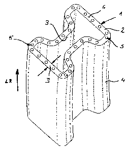
Figure 1 is a perspective view of the upper section of a chill tube in
accordance
with the invention.
Figure 2 is a changed perspective view, partially in section, of the tube mold
of
Figure 1.
Dla TAILED DESCRIPTIQN OF THE INVENTIQN
The invention is based on two measures which supplement each other in a
combining way, One measure is the reinforcement of the end regions of the
mold before the blasting calibration. This is done in particular bybuilding-up
welding, so that the losses in wall thickness due to the casting are
compensated. In order not to deform the bores in the mold wall in an
unacceptable fashion during the blasting calibration, they are now filled up
before the blasting calibration with a free-flowing material and tightty
closed at
the end. By using a free-flowing material, one can, on a comparatively simple
basis, also take into account differex~t cross sections of the bores. Filler
pieces
that are specifically geared to the cross sections of the bores are no longer
required. The expenditure in cost and the time-intensive effort drop out
completely.
The advantages of the present invention are particularly noticeable when, as
the
mold, a chill tube or an ingot mold made of copper or a copper alloy are
involved_
The bores can be filled up with an incompressible material, such as water.
However, the bores may also be filled up with a bulk material. In this case,
the
compressibility of the bulk material has a connection with its pore volume.
The
3

CA 02412655 2002-11-25
greater the compression of the bulk material and the finer the granulation,
the
lower is the pore volume of the bulk material and the greater is the strength
(resistance to compressionj,
A further specific embodiment of the method according to the invention is that
the bores are filled up with a mixture of an incompressible material and a
bulk
material.
If the bores are made to run the whole length of the tube wall and opening up
into their end faces, this simplifies the manufacturing of the bores, and thus
also the fabrication and recalibration of a mold.
The bores are preferably fabricated having a round cross section.
Chill tube 1, illustrated in Figures 1 and 2, has a double T-shaped cross
seckion.
It has a tube wall 2 having a thickness D which remains uniform around the
circumference. Consequently, the casting shape defined by inner wall 3 of tube
mold 1 exists also at outer surface 4.
Bores 5 run in the longitudinal direction IrR of chill tube 1 in tube wall 2.
Bores
5 extend parallel to one another at a distance apart and exit from end faces
$, 7
of tube wall 2, They have a circular cross section.
4

Representative Drawing
A single figure which represents the drawing illustrating the invention.
Administrative Status

2024-08-01:As part of the Next Generation Patents (NGP) transition, the Canadian Patents Database (CPD) now contains a more detailed Event History, which replicates the Event Log of our new back-office solution.

Please note that "Inactive:" events refers to events no longer in use in our new back-office solution.

For a clearer understanding of the status of the application/patent presented on this page, the site Disclaimer , as well as the definitions for Patent , Event History , Maintenance Fee  and Payment History  should be consulted.

Event History

Description Date
Time Limit for Reversal Expired 2009-11-25
Application Not Reinstated by Deadline 2009-11-25
Deemed Abandoned - Failure to Respond to Maintenance Fee Notice 2008-11-25
Letter Sent 2007-09-24
Request for Examination Received 2007-08-22
Request for Examination Requirements Determined Compliant 2007-08-22
All Requirements for Examination Determined Compliant 2007-08-22
Inactive: IPC from MCD 2006-03-12
Amendment Received - Voluntary Amendment 2004-02-24
Amendment Received - Voluntary Amendment 2003-09-12
Application Published (Open to Public Inspection) 2003-06-07
Inactive: Cover page published 2003-06-06
Letter Sent 2003-04-29
Inactive: Single transfer 2003-03-26
Inactive: First IPC assigned 2003-02-13
Inactive: Courtesy letter - Evidence 2003-01-21
Inactive: Filing certificate - No RFE (English) 2003-01-17
Filing Requirements Determined Compliant 2003-01-17
Application Received - Regular National 2003-01-17

Abandonment History

Abandonment Date Reason Reinstatement Date
2008-11-25

Maintenance Fee

The last payment was received on 2007-11-21

Note : If the full payment has not been received on or before the date indicated, a further fee may be required which may be one of the following

  • the reinstatement fee;
  • the late payment fee; or
  • additional fee to reverse deemed expiry.

Patent fees are adjusted on the 1st of January every year. The amounts above are the current amounts if received by December 31 of the current year.
Please refer to the CIPO Patent Fees web page to see all current fee amounts.

Fee History

Fee Type Anniversary Year Due Date Paid Date
Application fee - standard 2002-11-25
Registration of a document 2003-03-26
MF (application, 2nd anniv.) - standard 02 2004-11-25 2004-11-17
MF (application, 3rd anniv.) - standard 03 2005-11-25 2005-11-23
MF (application, 4th anniv.) - standard 04 2006-11-27 2006-11-17
Request for examination - standard 2007-08-22
MF (application, 5th anniv.) - standard 05 2007-11-26 2007-11-21
Owners on Record

Note: Records showing the ownership history in alphabetical order.

Current Owners on Record
KM EUROPA METAL AG
Past Owners on Record
ROLAND HAURI
Past Owners that do not appear in the "Owners on Record" listing will appear in other documentation within the application.
Documents

To view selected files, please enter reCAPTCHA code :


To view images, click a link in the Document Description column. To download the documents, select one or more checkboxes in the first column and then click the "Download Selected in PDF format (Zip Archive)" or the "Download Selected as Single PDF" button.

List of published and non-published patent-specific documents on the CPD .

If you have any difficulty accessing content, you can call the Client Service Centre at 1-866-997-1936 or send them an e-mail at CIPO Client Service Centre.


Document
Description 
Date
(yyyy-mm-dd) 
Number of pages   Size of Image (KB) 
Description 2002-11-24 4 177
Claims 2002-11-24 2 75
Abstract 2002-11-24 1 24
Drawings 2002-11-24 1 24
Representative drawing 2003-02-18 1 8
Claims 2003-09-11 2 46
Description 2003-09-11 4 158
Filing Certificate (English) 2003-01-16 1 160
Courtesy - Certificate of registration (related document(s)) 2003-04-28 1 107
Reminder of maintenance fee due 2004-07-26 1 111
Reminder - Request for Examination 2007-07-25 1 119
Acknowledgement of Request for Examination 2007-09-23 1 189
Courtesy - Abandonment Letter (Maintenance Fee) 2009-01-19 1 173
Correspondence 2003-01-16 1 24
Fees 2004-11-16 1 37
Fees 2005-11-22 1 37
Fees 2006-11-16 1 35
Fees 2007-11-20 1 36