Note: Descriptions are shown in the official language in which they were submitted.
CA 02413089 2007-10-01
23549-512
-1-
METHOD OF PLACING FIBERS INTO CHANNELS OF A MOLD
AND FIBER PLACEMENT HEAD FOR ACCOMPLISHING SAME
Technical Field
The present invention relates to a method of
automatically (robotically) placing fiber means into a plurality of
channels of a mold to form the ribs of a structural member. The
present invention also relates to a fiber placement head for use in
placing fiber means, preferably automatically, into a plurality of
channels of a mold utilizing a number of such heads.
Background Art
So-called isogrid structures have been developed that
are very advantageous in terms of weight and strength. Such
composite isogrid structures comprise a ribbed latticework by itself,
or with the addition of a skin or panel on one or both sides of the
ribs. Such isogrid structures are formed by placing fiber means into
the channels of a female mold. After completion of placement of the
fiber means into the channels, the resulting latticework is cured, if
necessary, and removed from the mold. A skin, such as a
composite layer, can be placed on one side of the latticework and
cured therewith prior to removal from the mold, or skin or panels can
be placed on one or both sides after removal from the mold. Skin
or panels can be secured to the ribs by, for example, an appropriate
adhesive. The skin can, for example, be a preimpregnated tape or
woven cloth. The panels can be made of any suitable material.
lsogrid structures can be used for a variety of purposes. By way of
example only, isogrid structures, be they in the form of panels,
cylinders, cones or any other suitable shape, can be used for
CA 02413089 2007-10-01
23549-512
2
decking, shipping containers, walking bridges, housing
material, automotive applications, shrouds, signs, support
structures, wings and fuselages, nozzles, spacecraft
structure, etc. The ribbed latticework by itself can be
used, for example, as reinforcement for a poured structure,
such as in concrete slabs.
Up until now, no quick and economical means have
been available for placing fiber means into molds to form
the ribbed isogrid latticework structure. Pursuant to some
heretofore known approaches, fiber means have been placed
into the mold one channel at a time. At best such
procedures are at least partially manually performed. A
procedure also known from conventional fiber placement
systems uses reciprocating shoes that push and pull a wide
band of fiber tows or tapes onto the top of the mold or into
the mold channels. This known process is not continuous, it
pulsates, and is very slow. In addition, the fiber
placement systems are bulky and expensive. Applicant is not
aware of any more relevant art, and certainly none that
provides for an automatic, multiple head lay-down process.
It is therefore an object of embodiments of the
present invention to provide a continuous fiber placement
method and fiber placement heads that are very time and cost
effective.
According to one aspect of the invention, there is
provided a method of placing fiber means into a plurality of
channels of a mold of any desired shape to form ribs of a
structural member, said channels extending in different
directions, said method comprising the steps of: providing
multiple fiber placement heads; while providing relative
CA 02413089 2007-10-01
23549-512
2a
movement between said mold and said heads in several
different directions, simultaneously placing said fiber
means into a number of said channels of said mold by means
of said heads; and repeating said relative movement and
placing step to dispose into said channels a desired
thickness of said fiber means.
There is also provided a multiple fiber-placement
head for placing fiber means simultaneously into a plurality
of channels of a mold, to form ribs of a structural member,
each of said heads comprising: a single motor driven wheel
for continuously withdrawing fiber means from a supply means
thereof and for feeding said fiber means through said fiber-
placement head, wherein said fiber means are disposed about
part of a circumference of said wheel; guide rollers for
guiding said fiber means through said fiber-placement head;
and means for compacting said fiber means in said channels,
wherein said wheel feeds said fiber means to said means for
compacting.
Brief Description of the Drawings
The features of embodiments of the invention, and
their technical advantages, can be seen from the following
description together with the claims and the accompanying
schematic drawings, in which:
Fig. 1 shows one exemplary embodiment of a female
mold with channels used for practicing the
CA 02413089 2007-10-01
23549-512
-3-
method and apparatus of the present
invention;
Fig. 1a is an enlarged view of several triangular nodal
areas of the mold of Fig. 1;
Fig. 2 is a front view of a table and gantry for placing
fiber means into the mold of Fig. 1;
Fig. 3 is a top view of the apparatus of Fig. 2;
Fig. 4 is a side view of the apparatus of Fig. 2;
Figs. 5a
and 5b are detailed views showing two positions of the
fiber placement head assembly of the present
invention;
Fig. 6 shows one exemplary embodiment of a ribbed
isogrid latticework structure without a skin
covering, showing attachment means;
Fig. 7 is a side view of a further exemplary
embodiment for processing a cylindrical mold;
Fig. 8 is a top view of the apparatus of Fig. 7;
Fig. 9 is a front view of the apparatus of Fig. 7;
Fig. 10 is a side view of another embodiment of the
present invention for processing a conical
mold; and
Fig. 11 is a top view of the apparatus of Fig. 10.
Disclosure of the Invention
The method of the present invention is characterized
primarily by providing relative movement between a mold and the
fiber-placement heads, while providing such relative movement
CA 02413089 2007-10-01
23549-512
-4-
simultaneously placing the fiber means into a number of the
channels of the mold by means of the heads, and repeating the
relative movement and placement as often as necessary to dispose
into the channels a desired thickness of the fiber means, thus
forming a lattice structure.
The fiber-placement head of the present invention is
characterized by a single motor-driven wheel for continuously
withdrawing fiber means from a spindle or other supply thereof,
means for guiding the fiber means into the channels of a mold, and
means for compacting the fiber means in the channels.
Pursuant to the present invention, a plurality of such
fiber-placement heads can be used in an apparatus that is
characterized by means for providing relative movement between
the heads and a mold, and means for automatically controlling the
heads and the relative movement between such heads and the
mold.
The inventive method and fiber-placement heads
make it possible to significantly reduce the time and cost for
disposing fiber means simultaneously into a number of the channels
of a mold to form the ribs of a structural member. In particular, by
the use of several such heads, the number of passes required to
effect placement of the fiber means into the mold channels is
reduced. In other words, a multiple lay-down process of fiber
means into the mold channels is provided. In addition, by reducing
manual operations in conjunction with the placement of the fiber
means into the mold channels, the time for effecting such fiber
placement is greatly reduced, as is the cost for the overall
production.
CA 02413089 2007-10-01
23549-512
-5-
Further specific features of the present invention will
be described in detail subsequently.
Detailed Description of Preferred Embodiments
Referring now to the drawings in detail, an example of
an isogrid mold used in conjunction with the method and apparatus
of the present invention is shown in Fig. 1. This mold is indicated
generally by the reference numeral 10, and is a female mold cast
from a male mold designed for a particular application, or can also
be made from a solid or hard material using a cutting device such
as a router. The mold can be made of polymeric material, including
rubber and foam, or can be made of some other material, such as
particle board. The aforementioned male mold can be a metallic
isogrid-patterned casting tray that is machined. However, it would
also be possible to provide a composite male mold using a
stereolithography mold process. The female mold 10 can then be
cast by pouring polymeric material, such as SILASTIC*, therein and
allowing the casting tray and SILASTIC silicone rubber to cure, for
example, at room temperature for 24 hours, to form the female
mold.
Grooves or channels 11 are disposed in one surface
of the mold 10 and form the isogrid design. These channels 11
extend in three different directions, preferably at 600 relative to one
another, e.g. +60, -60, and 0, so as to form triangles between them,
preferably equilateral triangles. The embodiment of the mold 10
shown in Fig. 1 is a flat mold. Other shapes of the moid 10 are also
possible, and will be discussed in detail subsequentiy.
The following discussion will first be made in
conjunction with the production of a flat panel using the flat female
* trade-mark
CA 02413089 2007-10-01
23549-512
-6-
mold 10 of Fig. 1. In order to place fiber means into the channels
11 of the mold 10, the mold is placed on an X, Y, Z computer table
as illustrated in Fig. 2; in this embodiment, the gantry 20 completes
the form of the X, Y, Z table. An isogrid structure, such as a panel,
is now ready for initial fabrication by having respective
preimpregnated fiber means, for example in the form of fiber tows,
placed into the grooves or channels 11, and the nodes 12, of the
mold 10. This is accomplished in an automatic manner by means
of a plurality of fiber placement head assemblies 22, which will be
described in greater detail subsequently. The fiber placement head
assemblies, or heads, 22 are movable relative to the mold 10 in
order to place fiber means into the channels 11 in several different
directions. For example, the heads 22 are disposed on the head
transport shaft 23 in such a way as to be movable thereon. In
addition, the gantry 20 is movable on a base portion 24 thereof both
in a direction perpendicular to the shaft 23 and at an angle thereto.
Spindles or spools 26 of impregnated fiber means are also disposed
on the gantry 20 by means of appropriate brackets. From the top
view of Fig. 3, it can be seen that a movement of the heads 22 at an
angle to both the shaft 23 and the track means 27, in order to place
fiber means in the angled channels 11, is accomplished by moving
the heads 22 not only along the shaft 23 but also in a direction
perpendicular thereto on the track means 27. This is accomplished
by the motors 28, which are computer driven, for controlling and
moving the heads 22 and the gantry 20. It would also be possible
to dispose a mold 10 on the table in such a way that rather than
being stationary, the mold is movable. Thus, for example, the mold
10 could be movable in two directions perpendicular to one another,
CA 02413089 2007-10-01
23549-512
-7-
or the mold could be movable in one direction while the heads 22
are movable in a direction perpendicular thereto, thereby being able
to place fiber means into all of the channels 11 of the mold 10.
Fig. 4 illustrates how the spindles 26 are respectively
disposed on shafts 30 that are mounted in support means 31. This
side view of the inventive apparatus also shows how the heads 22
travel along the shaft 23 and the track means 27 for placement of
fiber means into the channels 11 of the mold 10. The number of
spindles 26 should correspond to the number of heads 22, and are
preferably moved with the heads.
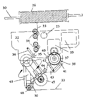
Figs. 5a and 5b are detailed views showing two
different positions of the fiber placement head assembly 22. The
heads 22 allow for the placement, compaction, heating and cutting
of the fiber means 33, such as a fiber tow or band of filaments
impregnated with resin and stored and withdrawn from the
respective spindles 26. The fiber means 33 is first fed through a
series of guide rollers 34. The fiber means 33 is then passed about
a guide roller 35 that is part of the rocker arm tensioning means or
mechanism 36, such as a spring-supported or any other suitable
tensioning means, for maintaining propertension on the fiber means
and for controlling the speed of the non-reciprocating wheel 37 of
the continuous feed system 38. This wheel 37, which is driven by
motor means 39, serves to continuously withdraw fiber means 33
from the spindle 26 and feed it through the fiber placement head
assembly 22. The fiber means is disposed about part of the
circumference of the wheel 37. Compaction rollers 40 and 41 are
provided in order to help hold the tacky fiber means 33 against the
wheel 37 and to prevent slippage of the fiber means relative to the
CA 02413089 2007-10-01
23549-512
-8-
wheel 37. The guide roller 42 is part of a further rocker arm
tensioning means 43 that maintains the proper tension of the fiber
means 33, whereby, by the means of a computer that reads the
tension, the speed of the wheel 37 is adjusted to speed up or slow
down feed of the fiber means if necessary. The two tensioning
means 36 and 43 are preferably synchronized with one another and
with the speed of the motor means 39, so that if the tension of the
fiber means 33 is not within a specified range, appropriate
adjustments can be automatically made. A further guide roller 44
is also provided.
During placement of the fiber means 33 into a channel
11 of the mold 10, a compaction roller 45 is lowered by means of
the rocker and rotating arm assembly 46, which includes a
pneumatic piston and solenoid motor 47. The pneumatic piston
serves to control the pressure of the compaction roller 45, which
ensures that the fiber means 33 is properly disposed in the channel
11 by applying appropriate pressure to the fiber means. A guide
roller 48, such as a V-shaped guide roller, which is also disposed on
the assembly 46, guides the fiber means 33 to the compaction roller
45. This guide roller 48 also serves for controlling the lay-down and
flaring (if desired) of the fiber means 33 as well as cutting thereof.
A curing means 49, such as a fiber optic tube, hot gas tube, etc.,
can be provided in order to partially cure or heat the fiber means 33,
if desired, prior to placement thereof in the channel 11. A cutting
means 50 is also provided in order to cut the fiber means 33 when
the end of a channel 11 has been reached, as will be described in
detail subsequently.
Pursuant to a presently preferred embodiment of the
CA 02413089 2007-10-01
23549-512
-9-
present invention, the number of fiber placement head assemblies
22 will correspond to the greatest number of channels 11 that
extend in a given direction in the mold 10. For example, in the
embodiment of the fiber placement system illustrated in Fig. 3, the
number of heads 22 will correspond to the number of channels 11
extending in either angular direction. In such a case, it is then
merely necessary, for each layer of fiber means 33, to make three
passes with the fiber placement head assemblies 22 at the mold 10
in order to place the fiber means into the mold channels 11, namely
once in each of the three directions in which the channels 11
extend. However, it is not absolutely necessary that the number of
heads 22 correspond to the number of channels 11 in any given
direction. For large molds, it may not be practical to do so.
Nonetheless, multiple heads 22 will always be provided so that the
number of passes in any given direction can be minimized, and the
speed, and hence cost, of production of the isogrid structures will be
very economical. Although, as indicated, the inventive process
operates with multiple fiber placement head assemblies 22, the
invention will now be explained in greater detail in conjunction with
only one head 22.
In Fig. 5a, the fiber placement head assembly 22 is
shown in a position prior to lay-down of the fiber means 33. The
head 22, as shown by the arrow, moves to the left as viewed in the
drawing. In this position prior to lay-down, the compaction roller 45
is raised and the guide roller 48 is lowered. This guide roller 48
could be provided with "grabber means" for the fiber means 33, or
could be provided with an appropriate surface that acts to "grab" the
fiber means. As illustrated, the fiber means 33 has been threaded
CA 02413089 2007-10-01
23549-512
-10-
through the head assembly 22 and is ready to be placed into a
channel 11. It should also be noted, as can be seen in Fig. 3, that
not all of the channels 11, namely those that extend at an angle, are
of the same length, so that varying lengths of fiber means are
placed in the channels by their respective heads 22. The position
of the head 22 illustrated in Fig. 5a is maintained, for example, until
the edge of the mold 10 has been reached. However, if the fiber
means 33 is to be flared, the position illustrated in Fig. 5a can be
maintained for a longer period of time. In this context, the term
flaring means that individual fiber means are to be separated from
one another. This takes place near the edge of the mold 10 by
means of a wider channel portion on the mold itself. Such flaring of
the fiber means 33 is used, for example, to provide a means for
either interconnecting isogrid structures or for connecting an isogrid
structure to another structure. Other means for such connections
are also possible and will be discussed in detail subsequently. In
order to effect the flaring or separation of the fiber means 33, the
rocker and rotating arm assembly 46 can be rotated as indicated in
Fig. 5a in order to alter the position of the guide roller 48. When it
is desired to compact the fiber means 33 within the channel 11, the
guide roller 48 is raised and the larger compaction roller 45 is
lowered, as shown in Fig. 5b. When the appropriate length of the
fiber means 33 in the channel 11 has been achieved, either at the
end of the channel or even beyond the channel, the fiber means 33
is cut by the cutting means 50; this is again accomplished in the
position of the rollers indicated in Fig. 5a. Depending upon the
conditions desired for the fiber means 33, such fiber means can be
heated, for example to increase tackiness, or partially cured by the
CA 02413089 2007-10-01
23549-512
-11-
aforementioned means 49 prior to placement of the fiber means 33
into the channel 11.
The foregoing procedure is repeated, either in the
same direction or preferably in alternate directions for reasons to be
discussed subsequently, as often as necessary in order to obtain
the desired thickness of fiber means in the channels 11. In order to
avoid thicker rib portions at the intersections of the channels 11 of
the mold 10, these areas of intersection are provided with widened
triangular nodes 12 (Fig. 1 a) that allow the fiber means to spread
out somewhat and prevent a build up at the intersection or cross-
over points. Alternating the direction of fiber lay-down will also
ensure that the fiber means 33 spread out evenly in the nodes 12.
Furthermore, these nodal areas, which are then rich in resin, are
critical for obtaining acceptable bonding to a skin or panel that is
placed on the ribs. In addition, these nodal areas can also be used
as attachment points, for example for mounting hinges, posts,
electronic boxes, etc., (see for example the hinges 14 mounted on
posts 15 in Fig. 6) and can also serve as a means to thereby
interconnect isogrid structures to one another or to other structure.
Structures could also be interconnected, for example, by I beam like
means. After completion of placement of the fiber means 33 into
the channels 11, the ribbed isogrid structure is complete, although
as previously discussed, the structure can then be cured, skin can
be attached or bonded thereon, etc. An example of the completed
ribbed isogrid structure, without the presence of a skin thereon, is
shown in Fig. 6. Although this structure is illustrated with the
attachment means 14, the structure does not necessarily have to
have attachment means. It should also be noted that attachment
CA 02413089 2007-10-01
23549-512
-12-
means could be attached to a skin or panel of such a structure, for
example again vi posts 15 or the like. Such posts 15 are shown
also in Fig. 1, and can be inserted, for example, prior to curing of the
fiber means 33 in the mold 10.
It should be noted that pursuant to one expedient
embodiment of the present invention, the fiber means 33 can be
placed into the channels 11 of the mold 10 by the heads 22 at a rate
of 90 feet per minute. The fiber means 33 have a width, for
example, of 1/4 to'/2 of an inch, although widths up to one inch
could be accommodated. By way of example only, a typicai flat
panel size could be 3 feet by 4 feet or 3 feet by 5 feet.
The previous discussion has been made in
conjunction with the placement of the fiber means 33 into the
channels 11 of a flat mold 10. However, it is also possible pursuant
to the present invention to use molds having any other desirable
shape. For example, reference is now made to Figs. 7-9, which
illustrate the use of the present invention in conjunction with a
cylindrical mold 10A. This mold can again be made from a
polymeric material, for example a flexible material, which allows the
mold to be wrapped to the desired shape. However, the mold 10A
could also be a solid material having channels machined therein.
In Fig. 7, the mold 10A is disposed on a rotatable
mandrel 52, which is motor driven. The fiber placement head
assemblies 22 are disposed on a circular part of the gantry 20A, as
shown in Fig. 9. The gantry 20A is mounted such that it can move
on the track means 27, so that the gantry 20A, and hence the heads
22, can be moved in the direction of the double arrow of Fig. 7 in a
direction parallel to the axis of the rotatable mandrel 52. Thus, by
CA 02413089 2007-10-01
23549-512
-13-
rotating the mold 10A on the mandrel 52, and/or by moving the
heads 22 in a direction parallel to the axis of the mandrel 52, fiber
means 33 can be placed into all of the channels 11 of the mold 10A
using the heads 22 in the manner previously described.
In a similar manner, the present invention can be used
to produce a conical isogrid structure, as shown in Figs. 10 and 11,
as well as Fig. 9.
As indicated previously, the inventive process and
fiber placement head assembly are intended to operate
automatically. This is accomplished by means of a programmable
controller, such as the controller 53 indicated in Figs. 7, 8 and 10,
11. The controller 53 is programmed to respond to and control a
number of operating parameters, including speed of feed of the fiber
means 33 through the fiber placement head assemblies 22, speed
of lay-down of the fiber means 33, the number of heads 22 that are
operating, the length of fiber means 33 to be placed into the
channels 11, the number of passes to be executed by the heads 22,
etc. The controller 53 is programmed in conjunction with the
specific isogrid structure being produced, and also responds to
various operating parameters, including tension on the fiber means
33 in the heads 22, by means of appropriate sensors that feed
information to the controller 23. Known means are provided for
sensing and transmitting parameter values to said controller 53 as
well as adjustment signals back therefrom to the head assembly 22
and other working components.
The fiber means 33 can be made of any suitable
material, including glass, fiberglass, graphite, polyamide resins, etc.
In addition, the fiber means can be in the form of fiber tows made up
CA 02413089 2007-10-01
23549-512
-14-
of a large number of individual filaments, they could be large
individual filaments, or they could be bands made up of several fiber
tows. The fibers are impregnated with varying types and amounts
of resin, for example thermosetting, thermoplastic, and non-thermal
cure resins, the selected quantity or proportion of which can vary
depending upon the resin material and the particular application of
the isogrid structure, especially whether or not skins or other panels
are to be attached to the ribbed structure.
ln view of the foregoing, it can be seen that this
invention not only provides a new fiber placement method, but also
provides a new head for realizing such a method, especially in an
apparatus that carries the mold with its channels, all for producing
an isogrid structure, for example in the form of panels, cylinders,
cones or any other desired shape.
The present invention is, of course, in no way
restricted to the specific disclosure of the specification and
drawings, but also encompasses any modifications within the scope
of the appended claims.