Language selection

Search

Patent 2413317 Summary

Third-party information liability

Some of the information on this Web page has been provided by external sources. The Government of Canada is not responsible for the accuracy, reliability or currency of the information supplied by external sources. Users wishing to rely upon this information should consult directly with the source of the information. Content provided by external sources is not subject to official languages, privacy and accessibility requirements.

Claims and Abstract availability

Any discrepancies in the text and image of the Claims and Abstract are due to differing posting times. Text of the Claims and Abstract are posted:

  • At the time the application is open to public inspection;
  • At the time of issue of the patent (grant).
(12) Patent: (11) CA 2413317
(54) English Title: LAYING HEAD BEARING WITH OFFSET PRELOADING
(54) French Title: PALIER A TETE D'APPUI AVEC PRECHARGEMENT DECENTRE
Status: Expired and beyond the Period of Reversal
Bibliographic Data
(51) International Patent Classification (IPC):
  • B21B 39/00 (2006.01)
  • B21B 13/00 (2006.01)
  • B21C 47/14 (2006.01)
  • F16C 25/06 (2006.01)
(72) Inventors :
  • SHORE, T. MICHAEL (United States of America)
  • WALSH, JAMES F. (United States of America)
(73) Owners :
  • SIEMENS INDUSTRY, INC.
(71) Applicants :
  • SIEMENS INDUSTRY, INC. (United States of America)
(74) Agent: SMART & BIGGAR LP
(74) Associate agent:
(45) Issued: 2009-02-03
(22) Filed Date: 2002-12-02
(41) Open to Public Inspection: 2003-06-14
Examination requested: 2002-12-02
Availability of licence: N/A
Dedicated to the Public: N/A
(25) Language of filing: English

Patent Cooperation Treaty (PCT): No

(30) Application Priority Data:
Application No. Country/Territory Date
10/082,986 (United States of America) 2002-02-26
10/300,060 (United States of America) 2002-11-20
60/340,190 (United States of America) 2001-12-14

Abstracts

English Abstract

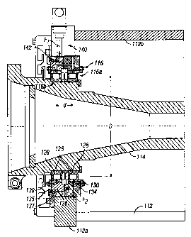
A bearing assembly is disclosed for rotatably supporting a quill in the housing of a rolling mill laying head. The bearing assembly includes first and second axially spaced roller bearing sets interposed between the quill and the housing. The bearing assembly also includes a force exerting unit for applying a radial preloading force to the first bearing set at a first location around the circumference thereof. The preloading force is opposed by a reactionary force acting on the second bearing set at a second location around the circumference thereof disposed 180° from the first location.


French Abstract

Ensemble de paliers servant à supporter un fourreau de façon rotative dans le logement d'une tête de pose de laminoir. L'ensemble de paliers comprend un premier et un second paliers à rouleaux axialement espacés et placés entre le fourreau et le logement. L'ensemble de paliers comprend également un dispositif servant à appliquer une force de précharge radiale au premier palier à un premier emplacement autour de la circonférence de celui-ci. € la force de précharge s'oppose une force de réaction agissant sur le second palier à un second emplacement autour de la circonférence de celui-ci à un angle de 180 degrés par rapport au premier emplacement.

Claims

Note: Claims are shown in the official language in which they were submitted.


What is claimed is:
1. A bearing assembly for rotatably supporting a quill in the housing of a
rolling mill laying head, said bearing assembly comprising:
first and second axially spaced roller bearing sets interposed between said
quill
and said housing contained in first and second cartridges respectively;
means for retaining said cartridges in an integral axially aligned and
abutting
relationship; and
force exerting means for applying a radial preloading force to said first
bearing
set at a first location around the circumference thereof, said preloading
force being
opposed by a reactionary force acting on said second bearing set at a second
location
around the circumference thereof disposed 180° from said first
location.
2. The bearing assembly of claim 1 wherein said first and second bearing
sets each comprise roller elements captured between circular inner and outer
races, said
inner races being fixed with respect to said quill and said outer races being
fixed with
respect to said housing.
3. The bearing assembly of claim 2 wherein said force exerting means is
supported by said housing and is arranged to act on the outer race of said
first bearing
set, and wherein said reactionary force is exerted by said housing acting on
the outer
race of said second bearing set.
4. The bearing assembly of claim 1 wherein said second cartridge is
received and rotatably fixed in a bore in a front plate of said housing, and
wherein said
first cartridge projects axially from said second cartridge and inwardly into
said housing.
5. The bearing assembly of claim 4 wherein said force exerting means is
constructed and arranged to engage said first cartridge.
7

6. The bearing assembly of claim 1 wherein the center to center distance
between said first and second bearing sets is between about 5 to 40% of the
nominal
diameter of said bearing sets.
7. The bearing assembly of claim 1 wherein said preloading force is
resiliently applied.
8. A rolling mill laying head comprising:
a housing;
a quill;
axially spaced front and rear bearing assemblies interposed between said quill
and said housing for rotatably supporting said quill, said front bearing
assembly
comprising first and second axially spaced roller bearing sets contained,
respectively, in
first and second cartridges;
means for retaining said cartridges in an integral axially aligned abutting
relationship; and
force exerting means for applying a radial preloading force to said first
bearing
set at a first location around the circumference thereof, said preloading
force being
opposed by a reactionary force acting on said second bearing set at a second
location
around the circumference thereof disposed 180° from said first
location.
9. The rolling mill laying head of claim 8 wherein said first and second
bearing sets each comprise roller elements captured between circular inner and
outer
races, said inner races being fixed with respect to said quill and said outer
races being
fixed with respect to said housing.
8

10. The rolling mill laying head of claim 9 wherein said force exerting means
is supported by said housing and is arranged to act on the outer race of said
first bearing
set, and wherein said reactionary force is exerted by said housing acting on
the outer
race of said second bearing set.
11. The rolling mill laying head of claim 8 wherein said second cartridge is
received and rotatably fixed in a bore in a front plate of said housing, and
wherein said
first cartridge projects axially from said second cartridge and inwardly into
said housing.
12. The rolling mill laying head of claim 11 wherein said force exerting
means is constructed and arranged to engage said first cartridge.
13. The rolling mill laying head of claim 8 wherein the center to center
distance between said first and second bearing sets is between about 5 to 40%
of the
nominal diameter of said bearing sets.
14. The rolling mill laying head of claim 8 wherein said preloading force is
resiliently applied.
15. A method of reducing clearances between the components of a bearing
assembly rotatably supporting a quill in the housing of a rolling mill laying
head, said
method comprising:
subdividing the bearing assembly into axially spaced roller bearing sets;
containing said roller bearing sets in cartridges retained in an axially
aligned
abutting relationship; and
applying a preolading force to one of said cartridges at a first location
around the
circumference of its respective bearing set, and opposing said preloading
force with
reactionary force applied to another of said cartridges at a second location
disposed 180°
from said first location.
9

Description

Note: Descriptions are shown in the official language in which they were submitted.


CA 02413317 2002-12-02
File: D-1184(CIP)
LAYING HEAD BEARING WITH OFFSET PRELOADING
BACKGROUND OF THE INVENTION
1. Field of the Invention
This invention relates to laying heads of the type employed in high speed rod
mills to
form the hot rolled exiting product into a helical formation of rings.
2. Description of the Prior Art
A conventional laying head is schematically depicted at 10 in Figure 1. The
laying
head includes a housing 12 containing a hollow quill 14 rotatably supported
between front and
rear roller bearing assemblies 16 and 18. The quill 14 carries a bevel gear 20
meshing with a
mating bevel gear 22, the latter being driven in a conventional manner by a
gear box and
motor (not shown).
A laying pipe 24 is carried by the quill 14. The laying pipe has an entry end
24a
aligned with the rotational axis X of the quill, and a curved intermediate
section 24b leading to
an exit end 24c spaced radially from the axis X.
1

CA 02413317 2007-11-21
In a typical modern day high speed rolling operation, a finished rod with a
5.5mm diameter exits the mill a speeds on the order of 112-120 m/sec and at a
temperature in the range of 750 to 1100 C. The rod can either be delivered to
the laying
head at these elevated temperatures, or it can be water cooled down to about
600-950 C
before it enters the entry end 24a of the laying pipe. The curvature of the
laying pipe,
coupled with its rotation about axis X, forms the rod into a helical series of
rings R. The
rings are delivered to a cooling conveyor (not shown), on which they are
distributed in
an offset overlapping pattern for additional cooling prior to being gathered
into coils.
When operating under these conditions, the laying head can attain rotational
speeds on the order of 1500-2250 RPM and higher, and the rotating components
of the
laying head, including the roller bearing assemblies supporting the quill, can
be exposed
to temperatures as high as 100-110 C. The roller bearing assemblies must thus
be
designed with adequate clearances to accommodate thermal expansion and
contraction.
It has now been determined that, particularly in the front bearing assembly
16,
which is relatively lightly loaded, at certain speeds such clearances can
cause
detrimental roller skidding and vibration.
SUMMARY OF THE INVENTION
It is desirable to eliminate or at least significantly reduce roller skidding
and
vibration caused by clearances in the front bearing assembly.
To this end, the front bearing assembly is subdivided into first and second
axially
spaced roller bearing sets. A radial preloading force is applied to the first
roller bearing
set at a first location around the circumference thereof. The preloading force
is opposed
by a reactionary force acting on the second bearing set at a second location
around its
circumference disposed 180 from the first location.
2

CA 02413317 2007-11-21
Accordingly, in one aspect of the invention, there is provided a bearing
assembly
for rotatably supporting a quill in the housing of a rolling mill laying head,
said bearing
assembly comprising: first and second axially spaced roller bearing sets
interposed
between said quill and said housing contained in first and second cartridges
respectively; means for retaining said cartridges in an integral axially
aligned and
abutting relationship; and force exerting means for applying a radial
preloading force to
said first bearing set at a first location around the circumference thereof,
said preloading
force being opposed by a reactionary force acting on said second bearing set
at a second
location around the circumference thereof disposed 180 from said first
location.
According to another aspect of the invention, there is provided a rolling mill
laying head comprising: a housing; a quill; axially spaced front and rear
bearing
assemblies interposed between said quill and said housing for rotatably
supporting said
quill, said front bearing assembly comprising first and second axially spaced
roller
bearing sets contained, respectively, in first and second cartridges; means
for retaining
said cartridges in an integral axially aligned abutting relationship; and
force exerting
means for applying a radial preloading force to said first bearing set at a
first location
around the circumference thereof, said preloading force being opposed by a
reactionary
force acting on said second bearing set at a second location around the
circumference
thereof disposed 180 from said first location.
According to another aspect of the invention, there is provided a method of
reducing clearances between the components of a bearing assembly rotatably
supporting
a quill in the housing of a rolling mill laying head, said method comprising:
subdividing
the bearing assembly into axially spaced roller bearing sets; containing said
roller
bearing sets in cartridges retained in an axially aligned abutting
relationship; and
applying a preolading force to one of said cartridges at a first location
around the
circumference of its respective bearing set, and opposing said preloading
force with
3

CA 02413317 2007-11-21
reactionary force applied to another of said cartridges at a second location
disposed 180
from said first location.
These and other advantages and features of the present invention will now be
described in greater detail with reference to the accompanying drawings,
wherein:
BRIEF DESCRIPTION OF THE DRAWINGS
Figure 1 is a schematic representation of a typical high speed rod laying
head;
Figure 2 is an enlarged longitudinal sectional view of the front portion of a
laying
head with the laying pipe removed, and incorporating a preloaded front bearing
assembly in accordance with one embodiment of the present invention;
Figure 3 is a sectional view taken along line 3-3 of Figure 2; and
Figure 4 is a view similar to Figure 2 of another laying head incorporating a
preloaded front bearing assembly in accordance with a second embodiment of the
invention.
3a

CA 02413317 2002-12-02
File: D-1184(CIP)
DETAILED DESCRIPTION OF PREFERRED EMBODIMENT
With reference to Figures 2 and 3, it will be seen that the housing 12
includes a front
plate 12a and a top plate 12b. The front bearing assembly 16 of the present
invention includes
inboard and outboard roller bearing sets 16a, 16b axially separated by a
center to center
distance "d". Preferably, the distance d is between about 5 to 40% of the
nominal diameter
"D" of the bearing sets 16a, 16b.
Each bearing set 16a, 16b includes roller elements 26 captured between
circular inner
and outer races 28, 30. The inner race 28 of bearing set 16b is seated on and
fixed relative to
the quill 14. The inner race 28 of bearing set 16a is seated on and fixed
relative to an inner
ring 32, which in turn is shrunk onto the quill.
The outer races 30 of the bearing sets 16a, 16b are contained respectively, in
cartridges
34, 36. The cartridges 34, 36 are received in axial alignment in a bore 13 in
the front housing,
plate 12a. Cartridge 34 is held against cartridge 36 by shoulder bolts 38
acting through
resilient so called `beliville" washers 39. A slight clearance is provided
between the shanks of
the bolts 38 and the holes in cartridge 34 through which they extend as well
as between the
cartridge 34 and the bore 13. These clearances are sufficient to accommodate
slight vertical
movement of cartridge 34 relative to cartridge 36.
Cartridge 34 includes an integral lobe 34a underlying a top plate 12b of the
housing.
Lobe 34a is engaged by an adjustable bolt 40 threaded through a bushing 42 on
the top plate
12b.
By appropriately adjusting the bolt 40, a downward preloading force Fi is
exerted on
cartridge 34, and hence on bearing set 16a at a first location along its
circumference. The
4

CA 02413317 2002-12-02
File: D-1184(CIP)
interposition of a resilient bellville washer 44 between the bolt 40 and lobe
34a insures that the
preloading force is resiliently applied. The preloading force may also be
applied by equivalent
alternative means, e.g., pressure cylinders, plastic or gas springs, etc.
The preloading force Fi on bearing set 16a is opposed by a reactionary force
Fa exerted
by the front housing plate 12a and acting on bearing set 16b at a second
location disposed 180
from the point of application of the preloading force. The preloading and
reactionary forces
Fi, F2 act in concert to eliminate clearances respectively in the upper half
of bearing set 16a
and the lower half of bearing set 16b. This in turn prevents or at least
beneficially reduces
both roller skidding and vibration attributable to normal operating clearances
between the
bearing components.
Figure 4 discloses a second embodiment of the invention wherein the front
bearing
assembly 116 again includes inboard and outboard roller bearing sets 116a,
116b, each
including roller elements 126 captured between inner and outer races 128, 130.
The inner
races 128 of both bearing sets are seated on and fixed relative to the quill
114. The outer race
130 of the inboard set 116a is contained within a cartridge 134 fixed in a
bore of the front
housing plate 112a. The outer race 130 of the outboard set 116b is contained
within a
cartridge 136, which in turn is held by a retaining 135 in a stepped bore 137
of cartridge 134.
A slight clearance between cartridge 136 and the bore 137 in cartridge 134,
coupled
with a modest retaining force exerted by a retainer ring 135, serve in concert
to accommodate
some slight vertical movement of cartridge 136 relative to cartridge 134.
A piston-cylinder unit 140 acts at a first location via an intermediate
arcuate foot 142 to
apply a preloading force Fl to cartridge 136 and hence to the outer race 130
of the outboard set
116b. This preloading force is again opposed by a reactionary force F2 exerted
against the
5

CA 02413317 2002-12-02
File: D-1184(CIP)
outer race 130 of the inboard set 116a at a location disposed 180 from the
point of application
of the preloading force. As with the first embodiment, the preloading force
may alternatively
be exerted by other equivalent means, e.g., that shown in Figures 2 and 3.
It thus will be seen that in a broad sense, the present invention operates to
preload one
bearing set by applying a force to its outer race at one location, with the
other bearing set
being preloaded by a reactionary force acting on its outer race at a location
disposed 180 from
the point of application of the preloading force. The preloading force may be
applied either to
the outer race of the inboard set, as shown in Figures 2 and 3, or to the
outer race of the
outboard set, as shown in Figure 4.
From the foregoing detailed description, it has been shown how the objectives
and
advantages of the invention may be obtained by several preferred embodiments.
However,
modifications and equivalents of the disclosed concepts such as readily occur
to those skilled in
the art are intended to be included within the scope of this invention.
We claim:
6

Representative Drawing
A single figure which represents the drawing illustrating the invention.
Administrative Status

2024-08-01:As part of the Next Generation Patents (NGP) transition, the Canadian Patents Database (CPD) now contains a more detailed Event History, which replicates the Event Log of our new back-office solution.

Please note that "Inactive:" events refers to events no longer in use in our new back-office solution.

For a clearer understanding of the status of the application/patent presented on this page, the site Disclaimer , as well as the definitions for Patent , Event History , Maintenance Fee  and Payment History  should be consulted.

Event History

Description Date
Time Limit for Reversal Expired 2014-12-02
Letter Sent 2013-12-02
Inactive: Office letter 2013-02-01
Inactive: Reversal of will be deemed expired status 2013-01-31
Letter Sent 2012-12-03
Letter Sent 2010-12-07
Revocation of Agent Requirements Determined Compliant 2010-05-31
Appointment of Agent Requirements Determined Compliant 2010-05-31
Inactive: Office letter 2010-05-18
Grant by Issuance 2009-02-03
Inactive: Cover page published 2009-02-02
Pre-grant 2008-11-20
Inactive: Final fee received 2008-11-20
Notice of Allowance is Issued 2008-06-20
Letter Sent 2008-06-20
Notice of Allowance is Issued 2008-06-20
Inactive: Approved for allowance (AFA) 2008-04-21
Amendment Received - Voluntary Amendment 2007-11-21
Inactive: S.30(2) Rules - Examiner requisition 2007-06-06
Inactive: IPC from MCD 2006-03-12
Application Published (Open to Public Inspection) 2003-06-14
Inactive: Cover page published 2003-06-13
Letter Sent 2003-03-14
Inactive: First IPC assigned 2003-02-14
Inactive: IPC assigned 2003-02-14
Inactive: Courtesy letter - Evidence 2003-01-28
Inactive: Filing certificate - RFE (English) 2003-01-23
Filing Requirements Determined Compliant 2003-01-23
Letter Sent 2003-01-23
Application Received - Regular National 2003-01-23
Request for Priority Received 2003-01-14
Amendment Received - Voluntary Amendment 2003-01-14
Inactive: Single transfer 2003-01-14
Request for Examination Requirements Determined Compliant 2002-12-02
All Requirements for Examination Determined Compliant 2002-12-02

Abandonment History

There is no abandonment history.

Maintenance Fee

The last payment was received on 2008-11-05

Note : If the full payment has not been received on or before the date indicated, a further fee may be required which may be one of the following

  • the reinstatement fee;
  • the late payment fee; or
  • additional fee to reverse deemed expiry.

Patent fees are adjusted on the 1st of January every year. The amounts above are the current amounts if received by December 31 of the current year.
Please refer to the CIPO Patent Fees web page to see all current fee amounts.

Owners on Record

Note: Records showing the ownership history in alphabetical order.

Current Owners on Record
SIEMENS INDUSTRY, INC.
Past Owners on Record
JAMES F. WALSH
T. MICHAEL SHORE
Past Owners that do not appear in the "Owners on Record" listing will appear in other documentation within the application.
Documents

To view selected files, please enter reCAPTCHA code :


To view images, click a link in the Document Description column. To download the documents, select one or more checkboxes in the first column and then click the "Download Selected in PDF format (Zip Archive)" or the "Download Selected as Single PDF" button.

List of published and non-published patent-specific documents on the CPD .

If you have any difficulty accessing content, you can call the Client Service Centre at 1-866-997-1936 or send them an e-mail at CIPO Client Service Centre.


Document
Description 
Date
(yyyy-mm-dd) 
Number of pages   Size of Image (KB) 
Drawings 2002-12-01 4 161
Description 2002-12-01 6 242
Abstract 2002-12-01 1 20
Claims 2002-12-01 2 76
Representative drawing 2003-02-19 1 18
Drawings 2003-01-13 4 130
Description 2007-11-20 7 286
Claims 2007-11-20 3 113
Claims 2007-11-20 4 129
Representative drawing 2009-01-18 1 18
Acknowledgement of Request for Examination 2003-01-22 1 173
Filing Certificate (English) 2003-01-22 1 160
Courtesy - Certificate of registration (related document(s)) 2003-03-13 1 130
Commissioner's Notice - Application Found Allowable 2008-06-19 1 165
Maintenance Fee Notice 2014-01-12 1 171
Correspondence 2003-01-22 1 23
Correspondence 2003-01-13 1 47
Correspondence 2003-04-02 1 10
Fees 2005-11-20 1 35
Correspondence 2008-11-19 1 38
Fees 2008-11-04 1 34
Correspondence 2010-03-08 11 652
Correspondence 2010-05-17 6 411
Correspondence 2010-05-17 1 29
Correspondence 2013-01-31 1 12