Note: Descriptions are shown in the official language in which they were submitted.
CA 02413743 2002-12-20
WO 02/01273 1 PCT/EPOI/07276
n
NIGHT-VISION DEVICE
The invention relates to a night-vision device, more particularly monocular,
according to
the preamble of claim 1 as well as to a device for the coupling in and
coupling out of
optical signals, particularly for being used in such a night-vision device,
according to claim
9.
Night-vision devices are essentially designed according to the following
principles. An
object lens, preferably fast, focusses the rays issuing from a subject to be
observed to the
input window of a residual-light amplifier. There the image of the subject is
electronically
amplified and because of the phosphorescent coating at the exit of the
residual-light
amplifier appears as a light green image on the amplifier's output window. The
subject's
amplified, green image is inverted via an optical image inverter system
associated with. but
where applicable separate from, the residual-light amplifier. This green image
is projected
into the user's eye via an eyepiece.
This results in a heavy, relatively expensive night-vision device of long
build having an
unfavorable position of the center of mass in applications that are not hand-
held.
From WO 96/10764, a monocular night-vision device is known in which two
reflective
optical elements having one reflecting surface each are arranged between the
residual-light
amplifier and the eyepiece. These reflecting surfaces, mutually offset, are
oriented against
one another. This night-vision device, too, has the structural disadvantages
of conventional
night-vision devices.
From US 4,000,419, furthermore, a coupling-in device for the coupling in of
optical
signals into the beam path between the final element of a night-vision device
on the side of
the eye and the user's eye is known. Depending on the particular situation,
such a device
can be attached to a night-vision device intended for it. By attaching the
coupling-in
device, the papillary distance is necessarily reduced, which significantly
reduces the
wearing comfort, particularly for wearers of glasses, and there may be
situations where an
optical post-adjustment is required.
CA 02413743 2002-12-20
WO 02/01273 2 PCT/EP01107276
The invention, to the contrary, is based on the task of providing a night-
vision device that
has a residual-light amplifier, where necessary with a conventional inverter,
but which
brings a distinct reduction of the length, weight, and production cost of the
device. The
distance between the device's center of mass and the user's head should also
be reduced,
particularly in applications that are not hand-held. Moreover, depending on
the applicable
situation, there is the underlying aim of adding or extracting visual
information via
additional devices.
This is achieved according to the invention, by realizing the characterizing
features of
claim 1 and claim 9, respectively. If it is said there that the optical axis
of the device's
object lens is supposed to be "essentially" parallel to the axis that leads to
the receptor,
then small departures from parallelism may in certain cases result from
parallax balance. If
it is said that the beam path between the residual-light amplifier and the
receptor is
I S determined by reflective optical elements, then this does not at all
exclude the simul-
taneous use of lens systems with refractive elements. We wish to make sure
here that by
the expression "definition of the beam path between residual-light amplifier
and receptor",
the bending of the optical axis of the beam of rays is to be understood.
Advantageous or alternative embodiments are described by the characteristics
of the
dependent claims.
In the invention, the beam path is bent on principle by reflective optical
elements between
the residual-light amplifier and a receptor such as, for instance, the human
eye and between
the residual-light amplifier and the subject. This leads to a considerable
reduction in weight
and length of the device that is advantageous for the wearing comfort of a
device according
to the invention, as well as to a reduction of production costs. In addition,
the solution
according to the invention that has four reflective optical elements can offer
the possibility
of a direct observation of the subject (like for instance through sun glasses)
and simul-
taneous perception of its amplified, generally green image that is
superimposed on the
"direct" image. The reflective surface of the first reflective element that is
associated with
CA 02413743 2002-12-20
WO 02/01273 3 PCT/EPOl/07276
the receptor will not restrict the field of vision for viewing without the
amplified residual
light when made of an appropriate size.
In an embodiment of the device according to the invention, the eyepiece can be
in two
parts when the reflective surface associated with the receptor is designed
without the
possibility of simultaneous viewing of the "direct" image. A first part of the
eyepiece is
arranged on the receptor ray axis between the mirror associated with the
receptor and the
receptor, and a second part of the eyepiece is arranged between the mirror
associated with
the receptor and the residual-light amplifier. It thus becomes possible to
realize a device of
smaller size and thus additionally optimize the position of the device's
center of mass in
applications.
A complete image inversion is possible when employing reflective elements.
Then a
specific inverter can be left out. In addition, individual reflecting surfaces
may be inte-
grated into other components of the device (for instance, into the eyepiece
mirror) unless
the mirrors are arranged in an uninterrupted sequence, and larger freedom of
design is
gained for the beam path bending.
By bending of the beam path, a given beam path can be adapted more closely to
the
geometric situation, and compact overall dimensions appropriate to given
applications can
be realized. Thus, an optimum position of the center of mass of the device can
be achieved,
particularly in helmet-based applications. For hand-held applications, too,
shapes that are
ergonomically advantageous can be achieved.
Further improvements are achieved by a bending of the beam path that can be
selected
variably, in which case the optical axis of the object lens and the axis of
the receptor ray
can be rotated relative to other components between them. Generally, attention
will have to
be paid to the fact that this rotation must always be mutually parallel. If
pivoting motions
of one of these axes become necessary in addition, then the other axis would
have to
perform the corresponding counter-pivoting motions in mutually parallel
planes.
CA 02413743 2002-12-20
WO 02/01273 4 PCT/EPO1/07276
It thus becomes possible to adapt a particular device to the individual
situation of the user.
and additional flexibility is gained in possible system integrations of the
device, for
instance as a night aiming device in daylight aiming devices, daylight range
finders, com-
passes and the like.
Even essentially mirror-symmetric modifications of the device can be
visualized, so that it
becomes superfluous to provide left and right versions of the device.
Two monocular devices can of course be combined into a binocular night-vision
device.
Depending on the situation, two identical devices can be combined on site to
hand-held or
helmet-based night-view goggles. The bent beam path makes possible a larger
object lens
separation for stereoscopic residual-light viewing in such a case.
The coupling-in and coupling-out device according to the invention offers the
possibility of
visual, silent information exchange even during residual-light observations
(situational
awareness), for instance when employed in action. According to the invention,
this device
is designed so that the distance between receptor and night-vision device is
not impaired by
the coupling-in or coupling-out device and that the latter can be plugged in
or out in the
field, occasionally even while the night-vision device is in operation. In the
part of the
beam path where the coupling-in or coupling-out device is inserted, the
optical beams
preferably are collimated. This makes it possible that a coupling-in or
coupling-out module
inserted into the beam path will have no effect on the beam path all the way
to the receptor,
i.e., constant viewing comfort is available even for wearers of glasses.
The most diverse applications are available for information to be coupled in,
which most
favorably would be differentiated in its color from the residual-light image:
Orientation
information (e.g., compass, GPS, distance information), target information
(position of a
potential target, susperimposed upon the residual-light image), alphanumeric
instructions
for action; an electronically adjustable haircross can be realized when
integrating the
device into an aiming system; blending in of image sequences from other
positions and
viewpoints, etc.
CA 02413743 2002-12-20
WO 02/01273 5 PCT/EPO1/07276
The most diverse applications for information to be coupled out are for
instance: docu-
mentation of the situation found, and of own actions executed (for instance,
police sharp-
shooters etc.), transmission of image sequences from one's own position to
deciders and
combat partners.
A modular design of the coupling-in and coupling-out device is distinguished,
on one hand
for its user friendliness and on the other hand for its great flexibility.
Thus, the mutual
dependence between the coupling-in or coupling-out device and the device into
which this
is received, will be minimized by providing a simple, reliable hardware
interface in the
form of a device socket. The user can carry such coupling-in or coupling-out
devices and.
depending on the application, plug them into a night-vision device or, where
applicable.
into another optical device having the corresponding device socket. Technical
progress
made in the coupling-in or coupling-out devices will have no negative
influence on the
technical level of an optical device provided with a corresponding device
socket so long as
the mechanical and optical design of the coupling-in or coupling-out device
remains
unchanged.
In the following the invention will be explained in greater detail and purely
in terms of
examples while referring to the embodiment variants represented in the figures
of the
drawing. The same designations and reference numerals are given to the same
parts
appearing in different exemplary embodiments and performing the same
functions. Shown
are:
in Figure 1 a an oblique-view representation of optical elements of a night-
vision device
according to the invention having a device socket for a coupling-in or
coupling-out
device for a visual information exchange;
in Figure 1 b a top-view representation of the optical elements of a rotatable
embodiment of
a night-vision device according to the invention;
in Figure 1 c an oblique-view representation of optical elements of a further
embodiment of
a night-vision device according to the invention with a device socket for a
coupling-in or coupling-out device as well as a two-part eyepiece;
CA 02413743 2002-12-20
WO 02/01273 6 PCT/EPO1/07276
in Figure 2a a lateral sectioned representation of an embodiment of a device
socket
according to the invention;
in Figure 2b a lateral sectioned representation of a coupling-in device
according to the
invention for information exchange; and
in Figure 2c a lateral sectioned representation of a coupling-out device
according to the
invention for information exchange.
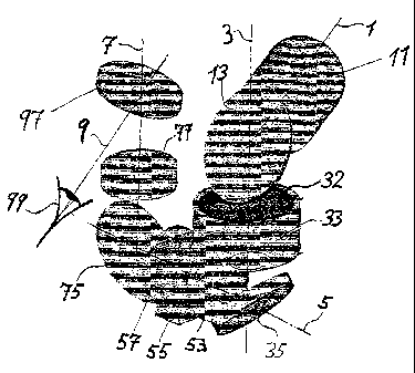
Figure 1 a shows the essential optical components of an embodiment of a
monocular night-
vision device according to the invention as well as their mutual arrangement.
This
embodiment comprises a residual-light amplifier 33, an object lens 11 having
an object
axis I, an eyepiece 77 having an eyepiece axis 7, lens systems, and four
reflective optical
elements with one reflecting surface each that are arranged in pairs
subtending specific
angles relative to each other. The reflective optical elements will generally
be planar but
may occasionally have a slightly aspherical shape. Instead of plane mirrors,
reflecting
prisms can be provided as the reflective elements. In Figure 1 a, the
respective reflecting
surfaces for instance are oriented as in a conventional Porro 2 system of
prisms. In contrast
to such a conventional system of prisms providing complete image inversion,
however, the
reflecting surfaces here are not arranged in a self contained assembly but are
associated
with different optical components of the night-vision device according to the
invention,
either individually or as a coplanar pair, that is, a pair having a common
plane of incidence
for optical rays.
The rays issuing from the subject are focussed by the object lens 11 via the
first reflective
element that is made in the shape of the object lens mirror 13, onto the input
window 32 of
the residual-light amplifier 33. The object lens mirror 13 is so oriented that
the object lens
axis 1 subtends aright angle with the optical axis of the residual-light
amplifier 33, which
is the amplifier axis 3. The beam of rays amplified by the residual-light
amplifier 33 is
again reflected by the second optical element that is made in the shape of the
amplifier
mirror 35. Here the amplifier mirror 35 has an orientation such that the
central axis of the
reflected beam of rays is parallel to a connecting axis 5. In this embodiment,
for instance,
the connecting axis 5 is normal to the plane going through the object lens
axis I and the
amplifier axis 3. The light rays reflected by the amplifier mirror 35 are
transformed by a
CA 02413743 2002-12-20
WO 02/01273 7 PCT/EPO1/07276
collimator lens system 53 to a preferably collimated beam of rays parallel to
the connecting
axis 5. This preferably collimated beam of rays may cross a device socket 55
provided in
this place. Then the beam of rays can be focussed by a focussing lens system
57 before
being once more deflected in a direction parallel to the amplifier axis 3 via
a third
reflective element that is made in the shape of a connecting mirror 75 to the
amplifier
mirror 35. The central axis of the beam of rays reflected at the connecting
mirror 75
coincides with the optical axis of an eyepiece lens system 77, which is the
eyepiece axis 7.
The amplifier mirror 35 and the connecting mirror 75 have a common plane of
incidence
here going through the amplifier axis 3, the connecting axis 5 and the
eyepiece axis 7. The
eyepiece lens system 77 indirectly projects the beam of rays reflected at the
connecting
minor 75 via the fourth reflective element that is made in the shape of the
receptor mirror
97, into the eye 99. Here the receptor minor 97 is oriented in such a way that
the receptor
ray axis 9 of the beam of rays reflected at the receptor mirror 97 is parallel
to the object
lens axis 1. Since the receptor mirror 97 can moreover be made so as to have a
wavelength-
dependent transmissivity, then the amplified night-vision image can be
superimposed onto
the real image (see-through system). A slight horizontal and vertical parallax
shift is seen.
only for subjects located in the immediate vicinity.
Figure 1 b shows an embodiment of a monocular night-vision device that has the
same
optical components as the night-vision device of Figure 1 a. In contrast to
the embodiment
in Figure 1 a, however, the reflecting surfaces are not oriented as in a Porro
2 system of
prisms. Moreover, in this embodiment, optical elements are interconnected
rotatably about
axes. Thus, on one hand the object lens mirror 13 and the object lens 11
connected
therewith are supported rotatably about the amplifier axis 3. On the other
hand, the
receptor mirror 97 in its turn is supported rotatably about the eyepiece axis
7. Here the
amplifier mirror 35, the collimator lens system 53, the device socket 55, the
focussing lens
system 57 and the connecting mirror 75 are rigidly interconnected via a
connecting piece
(not represented). Precautions must be taken at any rate that even after a
possible rotation
of the receptor mirror (97) and object lens mirror (13) the parallelism
between the receptor
ray axis 9 and the object lens axis 1 is preserved. This can for instance be
achieved by so-
called click stops or catches arranged in an identical fashion over the
rotating zones. This
parallel rotation could also be forced by a corresponding mechanical device. A
paraxial
CA 02413743 2002-12-20
WO 02/01273 8 PCT/EPO1 /07276
rotation of the receptor mirror 97 and object lens 11 has several advantages
at once. By
rotating both the receptor mirror 97 and the object lens 11 through
180°, the monocular
night-vision device of Figure 1b which here is adapted for right-eyed
observations could
basically be adapted for left-eyed usage. Paraxial rotation of the receptor
ray axis 9 and the
object lens axis 1 can generally also be used, as shown in Figure 1b, to
optimize the beam
path and thus the position of the device's center of mass for a commonly
adopted
attachment to the helmet while allowing for the individual situation of the
users. Here the
distance between the device's center of mass and the axis of rotation of the
helmet on the
user's head should be kept as short as possible.
Figure lc shows a further embodiment of a night-vision device according to the
invention
having a fully silvered receptor mirror 97. In contrast to the embodiments of
Figures 1 a
and 1b, only the residual-light-amplified image can be seen here, but not in
addition the
"direct" image. Instead, the eyepiece 77 is divided according to the invention
into two
eyepiece parts. A first eyepiece part 77a remains located between the receptor
mirror 79
and the connecting mirror 75. A second eyepiece part 77b is arranged on the
receptor ray
axis 9 between the receptor minor 97 and the receptor 99. It becomes possible
in this way
to realize the device in a smaller size and thus to additionally optimize the
position of the
device's center of mass in applications. Precautions must be taken that the
second eyepiece
part 77b is rigidly attached to the receptor mirror 97 if this embodiment is
designed as a
rotatable night-vision device according to the embodiment variant of Figure 1
b.
It can be seen from Figures 1 a, 1 b, and 1 c that the distribution of
components that is
presented is based on considerations of technical manipulation. that is.
compact size.
handiness, a favorable center of mass, etc. Of course, for a given optical
functioning of the
device, the individual components could be arranged in different ways between
the
reflective elements. For instance, the residual-light amplifier 33 could also
be located
between the amplifier mirror 35 and the connecting mirror 75. or even between
the
connecting mirror 75 and the receptor mirror 97.
Figure 2a shows a possible embodiment of a device socket 55, for instance for
a night-
vision device according to Figures la, 1b, and lc, that is located in the
connecting piece
CA 02413743 2002-12-20
WO 02/01273 9 PCT/EPO1/07276
between the amplifier mirror 35 and the connecting mirror 75. The recess 52
provided for
it in the connecting housing 51 encompasses for instance all of the beam cross
section of
the beam of rays 56, preferably collimated. Coupling-in and coupling-out
devices for the
coupling in or coupling out of visual information can of course also be
realized if only part
of the beam path is available for that purpose. In this embodiment, the beam
of rays 56 that
has been oriented parallel to the connecting axis 5 by the collimator lens
system 53, and is
preferably collimated, enters the recess 52 of the device socket 55 through a
first, plane
parallel sealing window 54. After passing through the recess 52, the beam of
rays 56,
preferably collimated, passes through a second plane parallel sealing window
54, and then
impinges upon the focussing lens system 57. With this arrangement according to
the
invention, on one hand a gas-tight separation of the device socket 55 from the
inner space
of the night-vision device that is filled with protective gas is guaranteed,
on the other hand
insertion of a partly transparent holder such as a plane parallel glass body
for the coupling-
in or coupling-out element can occur through the beam of rays 56, preferably
collimated.
into the recess 52, without impairing the beam path of the night-vision
device. Of course, a
coupling in or coupling out could also occur at other places of the device,
and even in parts
of the beam path that are not collimated, but the embodiment described in
Figure 2a is
advantageous because of its simplicity of design and its flexibility between
different device
types having an identical device socket concept. The notch 58 found at the
connecting
housing 51 which cooperates with a locking mechanism (not shown in Figure 2a)
allows a
protecting cover 59 to be fastened which is supposed to prevent contamination
and
mechanical damage to the device socket 55.
Figure 2b shows an embodiment of a coupling-in or coupling-out device
according to the
invention that is made in the shape of the coupling-in module 44. As shown,
the coupling-
in module 44 is inserted into the device socket 55 and locked. In this
situation the module
housing 41 overlaps the notch 58 and the locking elements (not shown in Figure
2b)
become engaged. An optically conducting support 42 for the coupling-in
element, for
instance a glass block which in addition to two plane parallel faces normal to
the
connecting axis 5 comprises the coupling-in element 45, for instance a
physical beam
splitter, in Figure 2b is inserted in such a way into the recess 52 that the
entire beam of rays
56 passes through it. However, the splitter area of the coupling-in element 45
may also be
CA 02413743 2002-12-20
WO 02/01273 10 PCT/EPO1/07276
very small. The sputter layer preferably has a composition such that at the
wavelengths
emitted by the residual-light amplifier it has a transmission maximum. The
coupling-in
element 45 has an orientation in the support 42 for the coupling-in element
which is such
that the coupling-in axis 4 of the projection optics 43 is coupled into the
beam path parallel
to the connecting axis 5 in the direction of the focussing lens system 57. The
radiant
surface can be a display 46, for instance an actively illuminated LCD screen,
an LED
display or some other light-emitting surface. The information presented on the
LCD screen
46 is made available via the coupling-in data interface 47. Apart from
alphanumeric
characters or graphical symbols, even moving pictures such as those coming
from a
thermal-image optical sight can be made available after appropriate scaling. A
"sensor
fusion'" of the most diverse sensors becomes possible by such an arrangement.
Figure 2c shows an embodiment of a coupling-in or coupling-out device
according to the
invention made in the shape of the coupling-out module 44. The coupling-out
module 66 is
realized in an analogous way in the same module housing 41. The support 62 for
the
coupling-out element which has the same outside dimensions as the support 42
for the
coupling-in element of Figure 2b comprises more particularly, contrarily, a
coupling-out
element 65 which reflects 10 to 20 % of the rays emitted from the residual-
light amplifier.
The coupling-out element 65 is oriented in such a way that it deflects a
coupling-out axis 6
of an imaging optics 63 parallel to the connecting axis 5 in the direction of
the collimator
lens system 53. Instead of the radiating surface, a receiving surface is found
in the
coupling-out module 66, such as a sensitive CCD array 64. The visual
information that is
coupled out is made available for instance through the coupling-out data
interface 67.
Basically, a combined coupling-in and coupling-out device having one coupling-
in element
and one coupling-out element each at a common element support is feasible.
Both the coupling-in data interface 47 and the coupling-out data interface 67
of the
coupling-in module 44 or coupling-out module 66 can be connected with radio
equipment
advantageously having its antenna at the helmet of the user. Wireless
transmission of the
optical information thus becomes possible.