Note: Descriptions are shown in the official language in which they were submitted.
CA 02414120 2002-12-13
IP 1348 1
Method and computer program product for modernisation of a lift installation
The invention relates to a method and a computer program product for
modernisation of a
lift installation according to the definition of the patent claims.
Lift installations for conveying persons and goods are relatively long-term
investment
products with service lives of 20 years and more. If after such a length of
time a general
overall of a lift installation arises, then the components of the lift
installation are often old in
terms of technology, which obliges a more or less complete exchange of
components.
1o Such an exchange of components of a lift installation is termed
modemisation in the
following. The modernisation is often carried out staggered in time, wherein
control units
and lift cages are modernised in a first stage, whilst drives are modernised
in the engine
room in a further stage and storey call transmitters are modernised in the
individual
storeys in a final stage.
The document US 5 352 857 is regarded as the closest state of the art for the
field of the
invention. US 5 352 857 discloses a method for modernisation of a lift
installation. The lift
installation consists of a group of lifts which convey users in a building,
wherein each lift is
controlled by a lift control. In order to maintain the transport capacity of
the lift installation
during modernisation, the modernisation is undertaken in modular manner and in
time
segments. A first method step consists of incorporating a group control and
several
adapter units. The adapter units are mounted at the lift controls and act
between the
individual lift controls and the new group control. In this manner there is
formed a
communications network which allows control of the individual lifts by way of
the new
group control. In further method steps existing components of the lift
installation are - at
freely selectable later moments in time - combined in modules. Existing lift
installation
components - such as the drive in the engine room, the storey call
transmitters in the
storeys, etc. - are then selected and removed in the manner of modules and
replaced by
new, corresponding lift installation components. When all modules have been
replaced,
the lift controls and the adapter units are removed in a further method step
and replaced
by a safety system interface in order to control the individual lifts by way
of the safety
system interface from the group control.
Disadvantages of this method of modernisation of a lift installation are that
the transport
capacity of the lift installation has to be maintained as best as possible
during the
CA 02414120 2002-12-13
IP 1348 2
modernisation, that the modular modernisation can be drawn out in time and
that the
method is material-intensive and thus costly in realisation.
In many cases, however, modernisation of a lift installation is carried out in
order to
produce an increase in the efficiency of the lift installation or to increase
the travel comfort
for the users. Thus, users want to be transported as quickly and directly as
possible, long
waiting times or a reboarding being perceived as disagreeable. In addition,
accelerations
and retardations of the lift cages should be hardly detectable by the users.
1o A first object of the invention is to provide a method and a computer
program product in
order to increase the efficiency of the lift installation or enhance the
travel comfort for users
even during modernisation of a lift installation. A further object of the
invention is to realise
this method and this computer program product economically and quickly.
Finally, the
invention shall be compatible with proven standards of machine construction
and the
electronics industry.
These objects are met by the invention according to the definition of the
patent claims.
According to the invention a lift installation which is disposed in a building
and to be
modernised is equipped with a destination call control within the framework of
preparatory
operations for modernisation of the lift installation. The destination call
control comprises
at least one storey terminal which is mounted at a storey. A user inputs a
destination call
report at the storey terminal or an identification code of the user is
recognised at the storey
terminal. The destination call control detects the boarding storey and the
destination
storey by a single destination call report or automatically associates a
destination storey
with an identification code recognised at a boarding storey. A destination
call report thus
comprises data not only with respect to the boarding storey, but also with
respect to the
destination storey. Traditional call reports containing only one item of
information or report
only a boarding storey or only a destination storey to the lift control are
superfluous by
virtue of the destination call control. In particular, the destination call
control avoids the
need for a user at a boarding storey to input a first call report at a storey
call transmitter in
order to call a lift to the boarding storey and then to input a second call
report in the lift
cage at a cage call transmitter in order to indicate a destination storey.
CA 02414120 2002-12-13
IP 1348 3
The destination call control comprises at least one computing unit which
evaluates the
destination call reports or unambiguously identifies users on the basis of
identification
codes and assigns a predetermined destination storey to identified users.
Further data,
such as data about the building or data about the actual user arrival, flow
into this
evaluation of the destination call reports or association of the
identification code.
According to a conveying result, a lift is allocated to each user and the user
is thus
conveyed in the shortest time or with the greatest travel comfort, for example
with low
waiting times or if possible without changeovers, to a destination storey.
The destination call control controls an existing lift control of the lift
installation, which is to
be modernised, by way of at least one device. The device has an intermediary
function in
that it converts the conveying result ascertained by the computing unit into
at least one call
report to the lift control. The computing unit communicates at least one
destination signal
to the device, which destination signal is converted by the device into at
least one call
report by which the lift control is controlled. In this manner the lift
installation to be
modernised can be equipped with a destination call control and is in that case
further
operated in accordance with call reports by the existing lift control.
The device documents the behaviour of the lift control as at least one travel
time profile.
The lift control is in that case to be regarded as a kind of 'black box', the
behaviour of
which is predictable in a learning process. For this purpose, at least one
signal of the lift
control is tapped off and the course thereof over time is documented as a
travel time
profile. The travel time profile contains data such as the acceleration, speed
and
retardation of the lift cage as a function of the length of the conveying
path, the carriage
load, etc. Advantageously, a large number of travel time profiles is
documented.
The invention relates to at least one computer program product which analyses
the travel
time profile and provides data with respect to the lift installation as at
least one advance
selector. The advance selector indicates for a travelling lift cage that
storey at which the
lift cage could still stop. For ascertaining the advance selector, the
computer program
product compares the course over time of the actual tapped signal with travel
time profiles
and selects that travel time profile which reproduces with the greatest
probability, or
substantially reproduces, the time course of the actual tapped signal.
Advantageously, an
advance selector is actualised for each lift of the lift installation at
continuous time intervals
and communicated to the destination call control. This actualised advance
selector flows
CA 02414120 2010-04-29
4
as further information into the evaluation of the conveying result by the
computing unit. The
advance selector enables a fast assignment of a user to a lift cage and thus
reduces waiting
times of the user. In addition, the advance selector makes it possible for the
lift cage to be
accelerated or retarded in hardly detectable manner and thus guarantees a high
travel comfort
for the user. The documentation of a large number of travel time profiles
enables an accurate
determination of the advance selector and optimises the efficiency of the lift
installation.
The equipping of the lift installation with a destination call control can be
carried out quickly, for
example within a few hours, for example in times of low loading of the lift
installation. For that
purpose the lift control is connected by way of at least one electrical line
with the device. The
storey terminal is mounted and the computing unit is installed. The system
consists of storey
terminal, computing unit and device, which are connected together by way of at
least one data
bus. The individual components of the system are standardised and can be
produced
economically.
The lift installation prepared in that manner for modernisation is simple and
uncomplicated to
modernise. Due to the fact that traditional call reports have become
superfluous by virtue of the
preparatory operations and that the efficiency of the lift installation has
been increased, a lift
installation can be modernised without disadvantages for the users.
Advantageously, a lift
installation with several lifts is modernised in modular manner in at least
one method step. By
contrast to the state of the art according to U.S. Patent No. 5,352,857, lift
installation components
are not, however, combined into modules and such a module modernises the lift
installation in
each method step, but at least one lift is substantially completely modernised
in each method
step. With advantage, a lift cage of a lift is modernised in one method step,
the drive of this lift is
modernised, the conveying cable of this lift is modernised, the lift control
of this lift is modernised
and the device is removed from this lift.
In one aspect, the present invention provides a method of modernising a lift
installation having at
least one lift controlled by at least one lift control by way of at least one
call report, comprising: a.
installing at least one floor terminal at each floor served by an lift
controlled by a lift
control for at least one of the input of destination call reports and for
recognition of identification
codes of users; b. installing at least one computing unit and connecting the
at least one
computing unit to said floor terminals for at least one of evaluating the
destination call reports
and association of destination floors with recognized ones of the
identification codes and for the
output of at least one destination signal; and c, installing at least one
modernising device and
connecting the at least one modernising device to said floor terminals and
said at least one
computing unit for reading the destination signal, for converting the
destination signal into at least
one call report and for controlling the lift control by way of the call
report.
CA 02414120 2010-04-29
4a
In yet another aspect, the present invention provides a computer program
product, comprising a
memory having computer readable code embodied thereon for modernising a lift
installation
having at least one lift, at least one lift control for controlling the at
least one lift by way of at least
one call report, characterised in that the computer program product has code
that compares at
least one target value actually detected at at least one output of the lift
control, or at least one
indication signal actually detected at at least one output of the lift
control, with target time profiles,
that the computer product has code that selects a travel time profile which
substantially
corresponds with the course of the actually detected target value or the
actually detected
indication signal over time and that the computer program product has code
that provides the
selected travel time profile as at least one advance selector.
The invention is explained in detail in the following on the basis of
exemplary embodiments
according to Figs. I to 3, in which:
Fig. 1 shows a part of a lift installation to be modernised,
CA 02414120 2002-12-13
IP 1348 5
Fig. 2 shows a part of the lift installation according to Fig. 1 after
conclusion of the
preparatory operations for modernisation and
Fig. 3 shows a schematic illustration of a part of a device.
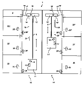
Fig. 1 shows a part of an exemplary embodiment of a lift installation to be
modernised,
with at least one lift 10, 10', 10" which is controlled by at least one lift
control 14, 14', 14".
The lift installation 1 is mounted in, for example, a building 2 with storeys
21, 21', 21" and
serves for conveying users such as persons or goods from one storey 21, 21',
21" to
1 o another storey 21, 21', 21". The building 2 comprises, for example, three
storeys 21, 21',
21" which are accessible by way of the lift installation 1.
The lift installation 1, comprises, for example, two lifts 10, 10' which are
arranged, for
example, parallel and adjacent to one another. Each lift 10, 10' comprises a
lift cage 11,
11' which is moved, for example suspended at a conveying cable 9, 9', by way
of a drive
12, 12' from one storey 21, 21', 21" to another storey 21, 21', 21". The
vertical conveying
direction of the lifts 10, 10' is indicated according to Figs. 1 and 2 by a
double arrow.
The drive 12, 12' is controlled by the lift control 14, 14', wherein in known
manner at least
one target value is produced, at least one regulating function is present and
at least one
start or at least one stop is realised. The actual position of a lift cage 11,
11' is detected,
for example, by way of at least one travel pick-up 24, 24', 24", 25, 25', 25"
and
communicated as at least one travel signal to the lift control 14, 14'. For
example, a first
travel pick-up 24, 24', 24" for a first lift 10 is mounted in each storey 21,
21', 21" and a
second travel pick-up 25, 25', 25" for a second lift 10' is mounted in each
storey 21, 21',
21".
The users pass by way of access means into or out of the lift cages 11, 11'.
For example,
the users in each storey 21, 21', 21" pass by way of an access means in the
form of a
storey door into or out of the lift cages 11, 11'. The lift cage 11, 11' has,
for example, an
access means in the form of a lift cage door through which the users pass into
or out of the
lift cage 11, 11'. In the lift cage 11, 11' the actual position of the lift
cage 11, 11' is
indicated to the user by way of at least one cage indicator 15, 15'.
CA 02414120 2010-04-29
6
The lift installation 1 is operated by users outside the lift cage 11, 11' by
way of at least
one storey call transmitter 22, 22', 22", 23, 23', 23" which is arranged, for
example, in a
storey 21, 21', 21" near the lift installation 1 and which has at least one
input means for
input of a first call report. For example, in each storey 21, 21', 21" a first
storey call
transmitter 22, 22', 22" is arranged near the storey door of the first lift 10
and in each
storey 21, 21', 21" a second storey call transmitter 23, 23', 23" is arranged
near the storey
door of the second lift 10'.
The lift installation 1 is operated by users in the interior of the lift cage
11, 11' by way of at
least one cage call transmitter 22, 22', 22" which has at least one input
means for input of
a second call report. These traditional call reports contain a single item of
information.
For example, the first call report indicates a conveying destination direction
(upwards or
downwards) or a boarding storey. The second call report indicates, for
example, a
destination storey.
The different components of the lift installation 1, such as storey call
transmitter 22, 22',
22", 23, 23', 23", cage call transmitter 13, 13', travel pick-up 24, 24', 24",
25, 25', 25", lift
control 14, 14', drive 12, 12' and cage indicator 15, 15' are connected
together by way of at
least one electrical line:
- For example, the storey call transmitter 22, 22', 22", 23, 23, 23" is
connected by
way of at least one electrical storey call transmitter line 16, 16' with at
least one input of
the lift control 14, 14' and thus enables communication of a first call report
to the lift control
14, 14'.
- For example, the cage call transmitter 13, 13' is connected by way of at
least one
electrical cage call transmitter line 18, 18' with at least one input of the
lift control 14, 14'
and thus enables communication of a second call report to the lift control 14,
14'.
For example, the travel pick-up 24, 24', 24", 25, 25', 25" is connected by way
of at
least one electrical travel pick-up line 17, 17' with at least one input of
the lift control 14, 14'
and thus enables communication of a travel signal to the lift control 14, 14'.
- For example, the drive 12, 12' is connected by way of at least one
electrical drive
line 19, 19' with at least one output of the lift control 14, 14' and thus
enables
communication of a target value to the drive 12, 12'.
For example, the cage indicator 15, 15' is connected by way of at least one
electrical cage indicator line 20, 20' with at least one output of the lift
control 14, 14' and
thus enables communication of at least one indicating signal to the cage
indicator 15, 15'.
CA 02414120 2002-12-13
IP 1348 7
These call reports, this travel signal, this target value and this indication
signal are, for
example, analog electrical signals of defined current strength, voltage,
frequency, period,
etc.
The operation of the lift installation 1 functions, for example, as follows:
A user actuates a storey call transmitter 22, 22', 22", 23, 23, 23" in a
boarding
storey.
According to a first call report, which is communicated by way of an
electrical
1o storey call transmitter line 16, 16' to the lift control 14, 14', the lift
control 14, 14' controls a
drive 12, 12' and moves a lift cage 11, 11' to the boarding storey.
After the lift cage 11, 11' has reached the boarding storey, the user boards
the lift
cage 11, 11' and actuates a cage call transmitter 13, 13'.
According to a second call report, which is communicated by way of an
electrical
cage call transmitter line 18, 18' to the lift control 14, 14', the lift
control 14, 14' controls the
drive 12, 12' and moves the lift cage 11, 11' from the boarding storey to the
destination
storey.
- After reaching the destination storey, the user disembarks from the lift
cage 11, 11'.
This lift installation 1 is now to be modernised. The invention is used for
this purpose.
Fig. 2 shows a part of an exemplary embodiment of a lift installation 1 after
conclusion of
preparatory operations in accordance with the invention for modernisation of
the lift
installation 1. Within the frame of the preparatory operations, the lift
installation 1 is
equipped with a destination call control 3.
The principle of the destination call control 3 is known from the document EP
0 246 395.
The destination call control 3 comprises at least one storey terminal 31, 31',
31" which is
arranged, for example, in each storey 21, 21', 21" near the lift installation
1. The storey
terminal 31, 31', 31" comprises at least one manual input means 32, 32', 32"
for input of a
destination call report or at least one recognition device 33, 33', 33" for
recognition of at
least one identification code. The recognition of an identification code
communicated by at
least one identification transmitter 34, 34', 34" to a recognition device 33,
33', 33" is known
from the document EP 0 699 617. The destination call control 3 detects, by a
single
destination call report, the boarding storey and the destination storey or
automatically
CA 02414120 2010-04-29
8
assigns a destination storey to an identification code recognised in a
boarding storey. A
destination call report comprises data regarding not only the boarding storey,
but also the
destination storey.
The destination call control 3 comprises at least one computing unit 30. The
computing
unit 30 is, for example, a commercially available personal computer or a work
station. The
computing unit 30 includes at least one processor and at least one data
memory. The
computing unit 30 is arranged at any suitable location, for example in a
vestibule of the
building 2 or in a computer room of the building 2, etc. The computing unit 30
executes at
least one computer program product for evaluation of destination call reports
or for
association of recognised identification codes with destination storeys. This
computer
program product is, for example, stored in the data memory and is loaded into
the
processor for execution thereof.
For example, an evaluation of destination call reports runs as follows:
The computer program product for evaluation of destination call reports
records an
input time of each destination call report with a statement of the boarding
storey as well as
of the desired destination storey in at least one request table.
This computer program product compares the distance between the boarding
storey and the actual position of the at least one lift cage 11, 11'. This
computer program
product also computes the distance between boarding storey and destination
storey. In
addition, this computer program product takes into consideration the actual
user presence
and computes possible intermediate stops along the conveying path.
On the basis of these data, this computer program product performs an
optimisation and ascertains for each destination call report at least one
conveying result.
The conveying result denotes the most favourable lift 10, 10' for conveying
the user, i.e.
the lift 10, 10' which conveys the user most quickly or with the highest
degree of travel
comfort to the destination storey.
An assignment of recognised identification codes with destination storeys
runs, for
example, as follows:
The computer program product for association of recognised identification
codes
with destination storeys records a recognition time of a recognised
identification code
under a statement of the boarding storey in a requests table.
CA 02414120 2002-12-13
IP 1348 9
In the data memory a user profile with at least one user-specific statement is
led to
a destination storey. This user profile is unambiguously identifiable by way
of an
identification address. Exactly one identification code exists for each
identification
address. For example, an identification address is able to be exactly
associated with an
identification code when the identification address and identification code
are identical.
This computer program product compares the recognised identification code with
the identification addresses of stored user profiles. This computer program
product then
precisely delivers a positive association result when one of the stored
identification
addresses is identical with the recognised identification code, but otherwise
this computer
io program product delivers a negative association result.
This computer program product records the destination storey in the requests
table.
This computer program product compares the distance between the boarding
storey and the actual position of the at least one lift cage 11, 11'. In
addition, this
computer program product computes the distance between the boarding storey and
destination storey. This computer program product also takes into
consideration the actual
user presence and computes possible intermediate stops along the conveying
path.
On the basis of this data, this computer program product performs an
optimisation
and ascertains at least one conveying result for each recognised
identification code. The
conveying result denotes the most favourable lift 10, 10' for conveying the
user, i.e. the lift
10, 10' which conveys the user the most quickly or with the highest degree of
travel
comfort to the destination storey.
The conveying result is converted. Advantageously, a lift 10, 10' allocated to
the
destination storey of the user is indicated to the user. For this purpose, the
storey terminal
31, 31', 31" has at least one lift indicator 35, 35, 35". The computing unit
30 executes at
least one computer program product for control of the lift installation 1. The
computing unit
controls the lift installation 1, which is to be modernised, by way of at
least one device
36, 36'. By the term "control" there is to be understood an indirect control.
In the present
30 case, the existing lift control 14, 14' is controlled by the computing unit
30 indirectly by way
of the device 36, 36'.
The storey terminal 31, 31', 31", the computing unit 30 and the device 36, 36'
communicate with one another by way of at least one data bus 37. The data bus
can be
any modern standard bus. Such data buses are known to the expert. The data bus
can
CA 02414120 2002-12-13
IP 1348 10
be based on electrical or optical signal transmission, such as an Ethernet
network, a
Token-ring network, etc. It can also be a radio network, an infrared network,
a radar
network, a radio beam network, etc. With knowledge of the present invention,
numerous
possibilities of realisation with respect thereto are open to the expert.
Fig. 3 shows a part of an exemplary embodiment of a device 36, 36'. The
computing unit
30 issues by way of the data bus 37 at least one destination signal to the
device 36, 36'.
The device 36, 36' comprises, for example, at least one input for the data bus
37 for
reception of the destination signal. For example, the destination signal is
transmitted to
1o the device 36, 36' in accordance with at least one communication protocol
of the data bus
37 and is read by the device 36, 36'. The device 36, 36' comprises, for
example, at least
one converter 361 which accepts the destination signal and converts it into a
call report.
The converter 361 is a commercially available and proven converter of the
electronics
industry.
The device 36, 36' and the lift control 14, 14' are connected together by way
of at least one
electrical line. The device 36, 36' comprises, for example, at least one
output for the issue
of call reports. This output is connected with the lift control 14, 14' by way
of at least one
storey call transmitter line 16, 16' as well as at least one cage call
transmitter line 18, 18'.
The call reports are issued to the lift control 14, 14' from at least one
signal generator 362
of the device 36, 36'. It is advantageous, but not obligatory, to arrange the
device 36, 36'
near the lift control 14, 14'. The signal generator 36 is a commercially
available and
proven signal generator of the electronics industry.
The operation of the modernised lift installation 1 functions, for example, as
follows:
A user inputs, in a boarding storey, a destination call report by way of a
manual
input means 32, 32', 32" of the storey terminal 31, 31' 31" or the user
carries an
identification transmitter 34, 34', 34" and communicates an identification
code to the
recognition device 33, 33', 33" of the storey terminal 31, 31', 31", which
identification code
is recognised by the recognition device 33, 33', 33".
The storey terminal 31, 31', 31" communicates to the computing unit 30 by way
of
the data bus 37 a conveying signal corresponding with the destination call
report or an
identification signal corresponding with a recognised identification code.
The computing unit 30 executes a computer program product and ascertains at
least one conveying result for the conveying signal or for the identification
signal.
CA 02414120 2002-12-13
IP 1348 11
At least one control signal for controlling the lift installation 1 is issued
as conveying
result.
The control signal comprises a user information signal which is communicated
by
way of the data bus 37 to the storey terminal 31, 31', 31" in the boarding
storey where the
user has made the destination call report. According to the user information
signal, the lift
10, 10' allocated to the destination storey of the user is indicated to the
user on the lift
indicator 35, 35', 35".
The control signal comprises at least one first destination signal which is
communicated by way of the data bus 37 to the device 36, 36'. According to
this first
destination signal the device 36, 36' issues by way of an electrical line a
first call report to
the lift control 14, 14'. According to this first call report the lift control
14, 14' controls a
drive 12, 12' and moves a lift cage 11, 11' to the boarding storey.
After the lift cage 11, 11' has reached the boarding storey, the user boards
the lift
cage 11, 11'.
- The control signal comprises at least one second signal which is
communicated by
way of the data bus 37 to the device 36, 36'. According to this second
destination signal
the device 36, 36' issues a second call report to the lift control 14, 14' by
way of an
electrical line. According to this second call report the lift control 14, 14'
controls the drive
12, 12' and moves the lift cage 11, 11' from the boarding storey to the
destination storey.
The user is conveyed without further action to the destination storey.
After reaching the destination storey the user disembarks from the lift cage
11, 11'.
The device 36, 36' has, at at least one input, at least one signal receiver
363 for detection
of at least one signal of the lift control 14, 14'. The signal is tapped at at
least one input or
at at least one output of the lift control 14, 14'. Advantageously, this input
of the device 36,
36' is connected by way of at least one drive line 19, 19' and/or at least one
cage indicator
line 20, 20' with the lift control 14, 14'. The signal receiver 363 detects,
for example, at
least one target value of the drive line 19, 19' and/or at least one
indication signal of the
cage indicator line 20, 20'. The signal receiver 363 is a commercially and
proven signal
receiver of the electronics industry.
The behaviour of this target value and/or of this indication signal over time
is documented
as at least one travel time profile. The travel time profile is a protocol
with regard to the
mode of function of the lift control 14, 14'. It documents numerous data about
the lift
installation 1, such as the acceleration, speed and retardation of a lift cage
11, 11' as a
CA 02414120 2002-12-13
IP 1348 12
function of the length of the conveying path, the cage load, etc. The travel
time profile can
be documented in any data format. For example, the device 36, 36' comprises at
least
one data memory 364 for storage of the travel time profile.
Two examples of signals tapped at the lift control 14, 14' serve for
illustration:
- The lift control 14, 14' communicates, for example, an indication signal on
the cage
indicator line 20, 20' as a form of acknowledgement for an input call report.
This
acknowledgement is communicated to a cage indicator 15, 15' of the lift cage
11, 11' and
is indicated there as the actual position of the lift cage 11, 11'. The
indication signal on the
cage indicator line 20, 20' is, for example, an electrical voltage of 5 V
direct voltage and is
of different length in time according to the respective storey to be
indicated. Thus, the
indication signal can, for indication of the first storey, be one second long,
whilst that for
indication of the second storey is two seconds long. The actual position of
the lift cage 11,
11' can thus be determined from this acknowledgement to the cage indicator 15,
15'.
- For example, the lift control 14, 14' communicates a target value on the
drive line
19, 19' for acceleration or retardation of a lift cage 11, 11'. The target
value for
acceleration of the lift cage 11, 11' is, for example, an electrical direct
voltage of 5 V. The
target value for retardation of the lift cage 11, 11' is, for example, an
electrical direct
voltage of 0 V. The acceleration or retardation of the lift cage 11, 11' can
thus be
determined from these target values.
Advantageously, the device*36, 36' executes at least one computer program
product which
analyses the travel time profile and determines or provides at least one
advance selector.
An advance selector indicates for a moving lift cage 11, 11' that storey at
which the lift
cage 11, 11' could still stop. For example, the device 36, 36' comprises a
data memory
364 for storage of the computer program product and at least one processor 365
for
carrying out the computer program product. The computer program product
compares, for
example, the actually detected indication signal or the actually detected
target value with
stored travel time profiles. The computer program product selects that travel
time profile
which substantially corresponds with the course over time of the actually
detected
indication signal or the actually detected target value and provides this
selected travel time
profile as an advance selector. By actually detected signal there is
understood a signal
obtained in real time or in quasi real time. For example, a signal is tapped
every 1/4 of a
second, preferably every 1/20 of a second, preferably every 1/1000 of a
second.
Advantageously, an advance selector is actualised at continuous time intervals
for each lift
CA 02414120 2002-12-13
IP 1348 13
10, 10' of the lift installation 1 and communicated to the computing unit 30.
For example,
an advance selector is communicated every 1/4 of a second, preferably every
1/20 of a
second, preferably every 1/1000 of a second, to the computing unit 30. With
knowledge of
the present invention, numerous possibilities of realisation of variants are
open to the
expert. Thus, it is entirely possible to perform the computer program product
on any
computer, for example on the computing unit 30 of the system or on a remote
server. In
this case the actually detected signal is communicated to the computing unit
or to the
remote server. Such a communication takes place, for example, by Internet.
1o An actualised advance selector flows as further information into the
conveying result. The
advance selector enables a rapid assignment of a user to a lift cage 11, 11'
and thus
reduces the waiting times of the user. In addition, the advance selector makes
it possible
that the lift cage 11, 11' is accelerated or retarded in hardly noticeable
manner and thus
guarantees a high travel comfort for the user. Through documentation of a
large,
substantially complete number of travel time profiles, the advance sector can
be
ascertained with a high degree of accuracy and the efficiency of the lift
installation I can
be optimised.
The preparatory operations for modernisation of the lift installation 1
consist in mounting at
least one storey terminal 31, 31', 31" and installing at least one computing
unit 30 as well
as at least one device 36, 36'. The system consisting of storey terminal 31,
31', 31",
computing unit 30 and device 36, 36' is advantageously composed of
prefabricated and,
for example, pre-configured units which are simple and quick to mount or to
install.
A storey terminal 31, 31', 31" is, for example, mounted in each storey 21, 21"
near the lift
installation 1. For example, a storey terminal 31, 31', 31" is mounted in each
storey 21,
21', 21" as a stand-alone apparatus near the two lifts 10, 10'. This stand-
alone apparatus
is, for example, fixed in the floor or to a wall of the storey 21, 21', 21" by
screws. These
storey terminals 31, 31', 31" replace the storey call transmitter, 22, 22',
22", 23, 23', 23" or
the cage call transmitter 13, 13'.
A device 36, 36' is installed at, for example, each lift control 14, 14'. For
this purpose, the
existing electrical storey call transmitter line 16, 16' to the storey call
transmitter 22, 22',
22", 23, 23, 23" or the existing electrical cage call transmitter line 18, 18'
to the cage call
transmitter 13, 13' is interrupted at the input of the lift control 14, 14'
and this input of the lift
CA 02414120 2002-12-13
IP 1348 14
control 14, 14' is, instead, connected by way of an electrical line with an
output of the
device 36, 36'. Advantageously, the existing electrical drive line 19, 19' at
the output of the
lift control 14, 14' is branched off and this output of the lift control 14,
14' is connected by
way of an electrical line with an input of the device 36, 36'. The existing
electrical cage
indicator line 20, 20' to the cage indicator 15, 15' is advantageously
interrupted at the
output of the lift control 14, 14' and this output of the lift control 14, 14'
is, instead,
connected by way of an electrical line with an input of the device 36, 36'. By
virtue of the
usually small number of inputs and outputs of the lift control 14, 14', this
installation of the
device 36, 36' is simple and quick to manage. The device 36, 36' is, for
example, fixed
near the lift control 14, 14' by screws.
The storey terminal 31, 31', 31", the computing unit 30 and the device 36, 36'
are, for
example, connected together by way of at least one data bus 37. The cable of
the data
bus 37 is, for example, laid in at least one existing cable shaft of the
building 2.
This lift installation 1 prepared in that manner for modernisation is simple
and complicated
to modernise. Advantageously, a lift installation 1 with several lifts 10, 10'
is modernised in
modular manner in at least one method step, wherein at least one lift 10, 10'
is
substantially completely modernised in each method step. With advantage, a
lift cage 11,
11' of a lift 10, 10' is modernised in one method step, the drive 12, 12' of
this lift 10, 10' is
modernised, the cable 9, 9' of this lift 10, 10' is modernised, the lift
control 14, 14' of this lift
10, 10' is modernised and the device 36, 36' of this lift 10, 10' is removed.