Note: Descriptions are shown in the official language in which they were submitted.
CA 02414127 2002-12-12
72NP06068
SYSTEM FOR CONNECTING AND LOCKING ROTOR BLADES OF AN AXIAL
COMPRESSOR
The present invention relates to a system for connecting and locking rotor
blades of an axial compressor.
More precisely, the invention relates to a system for connecting and locking
rotor blades which are fixed circumferentially and which are positioned in an
array on
the rotor disc of an axial compressor of a gas turbine.
The term "gas turbine" denotes the whole of a rotary heat engine which
converts the enthalpy of a gas into useful work, using gases obtained directly
from a
combustion process and supplying mechanical power on a rotating shaft.
The turbine therefore usually comprises one or more compressors or
turbocompressors, which compress air drawn in from the outside.
Various injectors supply the fuel, which is mixed with the air to form a fuel-
air
mixture for ignition.
The axial compressor is driven by a turbine, properly so called, or
turboexpander, which supplies mechanical energy to a user by converting the
enthalpy
of the gases burnt in the combustion chamber.
The turboexpander, the turbocompressor, the coinbustion chamber (or heater),
the output shaft for the mechanical energy, the control system and the
starting system
form the essential components of a gas turbine machine.
As regards the operation of a gas turbine, it is known that the fluid enters
the
compressor through a set of inlet ducts.
In these channels, the gas is characterized by low pressure and low
temperature, but as it passes through the compressor the gas is compressed and
its
temperature rises.
1
CA 02414127 2002-12-12
72NP06068
It then enters the combustion (or heating) chamber, where it undergoes a
further significant temperature rise.
The heat required to increase the gas temperature is supplied by the burning
of
liquid fuel introduced by injectors into the heating chamber.
The combustion is initiated by sparking plugs when. the machine is started.
At the outlet of the combustion chamber, the gas, at high pressure and high
temperature, passes through suitable ducts, reaches the turbine, where it
gives up
some of the energy accumulated in the compressor and in the heating
(combustion)
chamber, and then flows to the outside through the exhaust ducts.
Since the work transmitted by the gas to the turbine is greater than the work
absorbed by the gas in the compressor, a certain quantity of energy remains in
the
shaft of the machine, and this work, after deduction of the work absorbed by
the
accessories and by the passive resistance of moving mechanical parts,
constitutes the
useful work of the machine.
Where the compressor is concerned, the maximum compression pressure is
limited by the strength of the materials used.
Given the conditions of pressure, temperature and velocity of the rotating
members in which the compressor is made to operate, it will be understood that
the
various components, and in particular the blading, are particularly stressed
and
therefore subject to rapid deterioration.
To enable maintenance and replacement to be carried out, the blades of the
rotor disc are not made in one piece with it, but are fixed by their base
projections
which are inserted into suitable seats formed on the rim of the rotor disc.
In the connections of the rotor blades, the fixings are subjected, during the
operation of the machine, to high perpendicular, bending, and possibly
torsional
stresses.
2
CA 02414127 2002-12-12
72NP06068
It will be appreciated, therefore, that the blade connection procedure is a
crucial aspect of the design of any rotor.
In axial turbines, the most common type of blade fixing makes use of seats
formed in the rotor disc, having sides with a grooved profile, in which the
terminal
portions, or roots, of the blades are engaged.
These seats can be made in the form of peripheral grooves extending
essentially parallel to the axis of rotation of the rotor disc, so that the
blades are
inserted in an essentially axial direction.
A different type of blade fixing is provided by using what is known as
circumferential fixing, in which a circumferential groove is formed on the
outer
circumference of the rotor disc to enable the blades to be inserted in the
radial
direction.
A particularly significant problem in the field of the design of rotor blades
for
axial compressors is the problem of providing connections which reduce to a
minimum the down time for maintenance and replacement operations.
A first object of the present invention is therefore that of permitting the
speedy
assembly, dismantling and replacement of blades of the type fixed
circumferentially
to the rotor, by providing a blade connecting and locking system, with a
reduced
number of parts, which simplifies the removal of the locking devices and the
replacement of the blades without any need to dismantle the rotor.
One disadvantage encountered in the connections of blades to rotor discs in
the prior art is represented by the assembly tolerances: this is because
excessive
clearance in the assembly of the blades can cause dangerous vibrations, while
the
absence of such clearance can give rise to shrinkage due to the prevention of
thermal
expansion, causing additional stresses.
A second object of the present invention is therefore to provide a blade
connecting and locking system which ensures correct assembly tolerances.
3
CA 02414127 2009-01-02
,72NP06068
Another object of the present invention is to provide a system for connecting
and locking rotor blades of an axial compressor which provides high
reliability during
the operation of the machine.
In accordance with an embodiment of the invention there is provided a system
for connecting and locking blades which are fixed circumferentially to a rotor
disc of
an axial compressor, comprising a plurality of blades positioned in an array
along the
circumference of a rotor disc, each blade being provided with a shaped root
for
connection to the rotor disc; means of positioning and locking the blades,
which can
lock the blades in a predetermined position; a circumferential seat which has
a shaped
profile and which is formed along the circumference of the rotor disc, and
which can
house slidably in a radial arrangement the roots of the blades and the
positioning and
locking means; at least one insertion slot, intersecting the circumferential
seat to
permit the insertion of the roots of the blades and the positioning and
locking means;
the positioning and locking means comprising at least one block having a
lateral
profile in the shape of a dovetail with rounded corners, formed by a pair of
recesses
made in the upper portion of the block and capable of being retained by
counterparts
formed along the walls of the circumferential seat, the recesses being joined
in the
proximity of the base of the block to a pair of projections which can be
retained in
bends of the walls of the circumferential seat; the root and the block have,
subject to
the assembly tolerances, essentially identical profiles and essentially
identical
thicknesses (s), measured in the direction of sliding of the blades and of the
block in
the circumferential seat; and each of the blades comprising a quadrangular
platform
from whose upper face there extends a portion with an aerodynamic profile
designed
to compress the air, and from whose lower face there extends the root; and
wherein
the platform has a width (L), measured in the direction of sliding of the
blade in the
circumferential seat, equal to twice the thickness (s) of the root and of the
block, in
such a way that a space essentially sufficient for one block is provided
between two
contiguous blades.
The system for connecting and locking blades which are fixed
circumferentially to a rotor disc of an axial compressor according to the
invention
comprises the fixing of a plurality of blades positioned in an array along the
4
CA 02414127 2009-01-02
.72NP06068
circumference of a rotor disc, by the introduction of a shaped root of each
blade, by
the use of a means for positioning and locking the blades, into a
circumferential seat
formed along the circumference of the rotor disc, this seat being capable of
housing
slidably in a radial arrangement the roots of the blades and the positioning
and locking
means. At least one insertion slot, intersecting the circumferential seat, is
provided for
the insertion of the roots of the blades and the positioning and locking
means.
The characteristics of the system for connecting and locking rotor blades of
an
axial compressor according to the present invention will be made clearer by
the
following description and by the attached drawings, which relate to one
embodiment,
described by way of example and without restrictive intent, and in which:
Figure 1 is a perspective view of the connecting and locking system according
to the invention;
Figure 2 is a partial plan view of a rotor disc designed for the connecting
and
locking system according to the invention;
Figure 3 is a section taken through the line III-III of Figure 2;
4a
CA 02414127 2002-12-12
72NP06068
Figure 4 is an exploded view in partial section of details of the system
according to the present invention;
Figure 5 is a schematic section illustrating the connecting and locking system
according to the invention;
Figure 6 is a lateral view of a detail of the system according to the
invention.
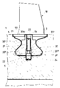
With reference to the figures, a multi-stage axial compressor comprises a
rotor
disc 1 having a plurality of stages 2, each comprising, along its
circumference, an
array of circumferentially fixed blades 10.
The blades 10 of each array are essentially identical, since their aerodynamic
and structural behaviour must be identical.
The structure of a blade 10 essentially comprises three main portions: a
quadrangular platform 11, preferably trapezoidal; a portion with an
aerodynamic
profile 12 designed to compress the air and extending from the upper face of
the
platform 11, and a root 13 which acts as the fixing in the rotor disc 1 and
extends
from the lower face of the platform 11.
The root 13 is the portion by which the blade 10 is connected to the rotor
disc
1, preventing the expulsion of the blade by centrifugal force.
The root 13 is shaped in such a way as to form a partial fixing in a
correspondingly shaped circumferential seat 3, formed along the circumference
of the
rotor disc 1.
In this context, it should be pointed out that, although reference is made to
a
rotor disc 1 carrying the blades 10, in some compressors a plurality of
blading stages
are connected directly to the rotor shaft which is designed for the purpose,
by the
provision of a number of circumferential seats equal to the number of bladed
stages to
be fitted.
CA 02414127 2002-12-12
72NP06068
The fixing of the root 13 in the circumferential seat 3 is considered to be a
partial fixing, since it allows the blade 10 to slide along the circumference
of the rotor
disc 1 but prevents its movement in the axial direction.
In order to form the partial fixing between the blade and disc, the root 13 of
the blade 10 and the circumferential seat 3 have profiles which match each
other, and
which can be made in various forms to meet different requirements of design
and
construction.
The root 13, when seen from the front with respect to the direction of sliding
in the circumferential seat 3, appears shaped in the form of a dovetail with
rounded
corners.
In its upper part, in the portion near the platform 11, the root 13 has a pair
of
recesses 13' which can engage with corresponding counterparts 3' formed along
the
walls of the circumferential seat 3.
The root 13 also has at its base a pair of projections 13" retained in
corresponding bends 3" formed in the walls of the circumferential seat 3 near
the base.
Preferably, the recesses 13', the counterparts 3', the projections 13" and the
bends 3" are made in pairs in the corresponding elements, but different forms
of fixing
which are equally effective can have only one shaped side.
The root 13 has a thickness s measured in the direction of sliding of the
blade
within the circumferential seat 3, and extends centrally with respect to the
platform
11 which has in the same direction a side whose measurement L is essentially
equal to
twice the thickness s.
The blades 10 are locked in the seat 3 by positioning and locking means,
comprising at least one block 20, also shaped in the form of a dovetail with
rounded
corners, and having a thickness s essentially equal to the thickness of the
root 13,
subject to the various tolerances specified for assembly, and having a profile
essentially reproducing that of the root 13, so that it can be inserted into,
and slide
within, the circumferential seat 3.
6
CA 02414127 2002-12-12
72NP06068
In particular, the block 20 has in its upper part recesses 20' which reproduce
the profiles of the counterparts 3' formed along the walls of the
circumferential seat 3,
and at its base a pair of projections 20" identical to the projections 13" of
the roots 13
and capable of being retained in the bends 3" of the walls of the
circumferential seat 3.
The block 20 also has a thickness s, measured in the direction of sliding of
the
blade 10 and the block 20 within the circumferential seat 3, which is
essentially equal
to the thickness s of the roots 13, subject to the necessary assembly
tolerances.
To achieve effective locking, at least two blocks 20 are provided, these being
positioned a certain distance apart, according to the procedures which will be
made
clear in the rest of the description.
Each block 20 has a central through hole 21, which passes vertically through
it, for the insertion of a dowel 22.
The dowel 22 of each block 20 comprises a body 23 and a head 24 designed
for engagement in a corresponding blind hole 5 formed in the base of the
circumferential seat 3 for fixing each block 20 to the rotor disc 1.
For fixing the block 20 to the rotor disc 1, the central hole 21 is threaded
in the
area which houses the body 23 of the dowel, which is also correspondingly
threaded.
Therefore, when the dowel 22 is screwed in, the head 24 is made to bear on
the base of the blind hole 5, thus locking the corresponding block and
consequently
the whole array of blades 10,
To enable the roots 13 and the blocks 20 to be inserted radially into the
circumferential slot 3, at least one insertion slot 4 is p:rovided,
intersecting the said
circumferential seat 3.
Preferably, a single insertion slot 4 is provided, in order to increase the
reliability of the system, but the provision of two insertion slots 4 in
diametrically
opposite locations with respect to the rotor disc provides better balancing
during
rotation.
7
CA 02414127 2002-12-12
72NP06068
In this case, the components of the whole connecting and locking system are
doubled.
The insertion slot 4 is, in practice, an aperture of essentially quadrangular
shape, and its dimensions are slightly greater than the dimensions of the
roots 13 and
of the blocks 20, because sufficient assembly clearance is provided to enable
the roots
13 and the blocks 20 to be inserted radially into the circumferential seat 3.
Pairs of securing blades 10', located next to each block 20, are also provided
for the assembly of the system according to the invention.
These securing blades 10' are essentially identical to the blades 10, but each
of
them has an aperture 14, which is generally semicircular, or quadrangular if
particular
constructional requirements have to be met.
This aperture 14 is formed on the edge of the platform 11, adjacent to the
corresponding edge of the other securing blade making up the pair.
These apertures are made in central positions, to a:llow access to the dowel
22.
In a corresponding way, a small block or bush 20a extends from the upper face
of the block 20a, this bush also being formed in a central position and having
the
central hole 21 passing through it.
The bush 20a is designed to be inserted into the said semicircular or
quadrangular apertures 14 formed in the platforms 11 of the securing blades
10'.
If the apertures 14 are made quadrangular in order to meet constructional
requirements, the bush is also made quadrangular.
In order to understand more clearly the advantages of the connecting and
locking system according to the invention, reference should be made to its
assembly
on the rotor disc 1.
The blades 10 are first inserted through the insertion slot 4 and are slid
circumferentially along the circumferential seat 3, after which a securing
blade 10' is
8
CA 02414127 2002-12-12
72NP06068
inserted, followed by a block 20 and then another securing blade 10', in such
a way
that the two semicircular apertures 14 are joined to form an aperture which
can
receive the hollow cylindrical body 20a.
Two other blades 10 are then inserted, and finally two more blades 10', with
the second block 20 between them, are inserted in the same way as before.
Finally, the whole array is slid within the circumferential seat 3 until the
two
blocks 20, or more precisely their central holes 21, are brought in line with
the blind
holes 5, so that the dowels 22 can be screwed in until their heads 24 enter
the blind
holes 5.
When the assembly is complete, the blades 10 and the securing blades 10" are
in contact with each other along the edges of their platforms 11 perpendicular
to the
direction of sliding of the blades, and a space is provided between the roots
13 of the
two pairs of contiguous securing blades 10' for housing the blocks 20.
The decision to position and fix the blocks at a spacing enabling four blades,
namely two blades 10 and two securing blades 10', to be placed between them,
was
made in order to provide an optimal solution to the problem of the tolerances
and
clearances required for carrying out the assembly.
However, it should be emphasized that this decision was also dependent on the
dimensions of the blades of one stage, and that it could, therefore, be
modified, with
the insertion of a different number of blades 10 between the blocks.
In particular, this decision makes it possible to keep the blades which are
close
to the insertion slot 4 in their predetermined positions, anci avoids a
situation in which
the insertion of a greater nuniber of blades between the two blocks might, as
a result
of an unforeseen sum of tolerances, cause one of the blades to be too closely
aligned
with the insertion slot, thus risking the expulsion of this blade.
Advantageously, the provision of a single insertion slot for the whole array
of
blades of each stage of the rotor disc further reduces the possibility of
occurrence of
such problems.
9
CA 02414127 2002-12-12
72NP06068
In this context, it should be noted that, in the arrangement according to the
preferred embodiment of the invention, on completion of assembly, two
contiguous
blades are positioned symmetrically with their platforms 11 covering the
insertion slot
4, these platforms having the function of re-creating the flow duct in the
areas above
the root housing slot.
Therefore, given the values of the thickness s of the root 13, the width L of
the
platform 11 which is equal to twice the thickness s, and the width of the
insertion slot
4 which is slightly greater than the thickness s, the roots of the two blades
are
essentially aligned in the insertion slot 4, and it is theref:ore easy to
imagine how a
minimal displacement of the blade could bring its root into a position of
excessive
projection into the insertion slot, thus making the locking unstable or even
causing the
blade to be expelled from the circumferential seat during the rotation of the
rotor disc.
Finally, the arrangement according to the invention makes it possible to avoid
an excessive closeness of the blocks which, by creating irregularities in the
circular
symmetry of the array of blades, perturb the rotation of the rotor disc.
The above description clearly indicates the characteristics of the connecting
and locking of blades on a rotor disc of an axial compressor of a gas turbine
which is
the object of the present invention, and also makes clear the additional
advantages,
which include, in addition to those mentioned previously:
- an increased average life of the components;
- a higher rotation speed of the machine or an increase in the temperature of
the fluid,
or an appropriate combination of the two factors.
Finally, it is evident that the system designed in this way can be modified
and
varied in numerous ways, all included within the scope of the invention;
moreover, all
the components can be replaced with technically equivalent elements.
In practice, the materials used, as well as the shapes and dimensions, can be
varied at will according to technical requirements.