Note: Descriptions are shown in the official language in which they were submitted.
CA 02414358 2005-04-12
DEFORDSABLE 6~1ALL OF A ~.'LJBULAR
The present invention relates to a deformable member.
Particularly, but not exclusively, thE: present invention
relates to a deformable member for use in a well tool,
especially for providing a metal to metal seal, and to a
well tool with a deformable member.
It is known to provide metal to metal seals to carry
out a wide variety of sealing operations within tubing such
as suxface fluid pipe lines and well. tubing of an oil or
gas well. Such metal to metal seals are complex, expensive
to manufacture, must be preformed anal often result in
permanent deformation so that the seals cannot be reused.
Also, it is known to provide resilient seals which do not
provide metal to metal sealing in such tubing, are cheap
and which are. reusable, however, such resilient seals have
I5 disadvantages that they do not have the strength of metal
to metal seals and cannot be used in aggressive
environments which degrade the seal.
Furthermore, it is known to provide a wide variety of
tools far carrying out well operations within tubing of a
well, such as an oil or gas well, the tools requiring a
seal to enable specific well operations to be carried out.
Examples of such tools include tubing hangers, packers,
bridge plugs, straddles, gravel-pack packers and the like.
Each of such tools are often compl~;x, including many
interrelated parts, and require complex running, -support,
activating/deactivating and retrieving' tools to achieve
sealing and allow the well operation to. be carried out
using the tool. furthermore, complex operations are often
required to be performed in order to locate,
activate/deactivate and/or. retrieve the tools.
Similar problems are encountered with tools provided
in tubing such as gas or oil pipelines located above
ground.
CA 02414358 2003-O1-02
WO 02/04783 PCT/GBO1/03072
2
Disadvantages associated with such tools are therefore
the relative complexity of the tools, the complexity of the
operations which are required to be carried out in order to
locate, activate/deactivate and/or retrieve the tools, and
the abovementioned disadvantages of presently known seals.
An annular seal is disclosed in US patent no.6,182,755
(Mansure) which includes a collapsible bellows. The
bellows is expanded for insertion downhole to reduce its
outer diameter and is set by compaction to provide a seal
or anchor. However, the seal of US6,182,755 is not
initially rigid, which will create problems during running-
in and tripping out of a borehole, when the seal is in the
expanded position. Also, the bellows itself requires
support through support shoulders to provide an effective
seal/anchor; whilst embodiments are disclosed without such
support shoulders, such would be unlikely to provide an
effective seal/anchor in harsh downhole environments.
It is amongst the objects of the present invention to
obviate or mitigate at least one of the foregoing
disadvantages. Embodiments of the invention may provide an
improved seal with the integrity of a metal to metal seal,
but which may advantageously be applied to a wide variety
of applications.
According to a first aspect of the present invention,
there is provided a deformable member for use as a seal or
anchor, said deformable member having a generally hollow
cylindrical body defining a cylinder wall having a wall
thickness which permits the cylinder wall to deform in
response to an applied force, to form a ring of material
around the circumference of the cylindrical body, the ring
being generally upstanding from the surface of the cylinder
wall.
The ring may be formed on the outer surface of the
cylinder wall or the inner surface of the cylinder wall.
Conveniently the applied force is an axial force
CA 02414358 2003-O1-02
WO 02/04783 PCT/GBO1/03072
3
applied at an end of the cylinder. Alternatively the
applied force is a radial force.
According to a second aspect of the present invention,
there is provided a deformable member having a generally
hollow cylindrical body defining a member wall, the wall
having at least three circumferential lines of weakness
therein, said lines of weakness being spaced along a main
axis of the body, two of said lines of weakness being
provided in one of an inner and outer surface of the wall
and the other one of said lines of weakness being provided
in the other one of said inner and outer surfaces of the
wall, the axially outermost lines of weakness defining a
zone of deformation of the body, wherein the member is
deformable in the deformation zone in response to an
applied force, in a direction transverse to said body main
axis, said direction determined by the location of the
other one of said lines of weakness in the wall.
Preferably, the applied force is an axial force.
Alternatively, the applied force is a radial force.
Preferably also the direction of deformation is determined
by the location of the other one of said lines of weakness.
In this fashion, a deformable member may be provided,
which member is deformable on application of an axial force
thereon. The deformation occurs in the deformation zone of
the member. This provides a wide number of uses for the
deformable member, for example, as a metal to metal seal,
and results in the member having a larger, or a smaller
diameter in the zone of deformation. Sealing is achieved
by deformation of the member in the deformation zone, to
bring the member into contact with a secondary body with
which it is desired to achieve sealing contact.
Preferably, the deformable member is used in well
tools. In this fashion, the deformable member may form
part of a well tool, wherein the member is deformable to
carry out a sealing operation. The deformable member may
CA 02414358 2003-O1-02
WO 02/04783 PCT/GBO1/03072
4
be carried on a support member of the well tool.
According to a third aspect of the present invention,
there is provided the deformable member of the second
aspect of the invention for use in a well tool.
The deformable member may be movable between a
substantially undeformed position and a deformed position.
This allows the deformable member to be run into, for
example, well tubing, in a first undeformed position before
being forced into a second deformed position to carry out
a desired well operation, by application of an axial force.
Alternatively, the deformable member may be initially
partially deformed or otherwise preformed into a desired
shape, and may be moveable between the partially deformed
or preformed position and a further deformed position.
This may assist in allowing controlling of a desired well
operation, and/or may allow the deformable member to carry
out a desired operation in both the partially deformed or
preformed position and in the further deformed position.
The deformable member may be carried on a support
member of the well tool, and may form part of the well tool
.itself .
Preferably, the deformable member is locatable in a
tube for providing sealing contact with an inner surface of
the tube, by outward deformation of the deformable member
into contact with the tube. Additionally or alternatively,
a tube may be located within the deformable member for
sealing contact therewith, by inward deformation of the
deformable member into contact with an outer surface of
inner tube.
Conveniently, the deformable member is of a deformable
metal material, for providing metal to metal sealing with
the tube, which is also of a metal material. The
deformable member may be a carbon steel, stainless steel or
other suitable non-ferrous alloy. Alternatively, the
deformable member may be a plastics or composite material.
CA 02414358 2003-O1-02
WO 02/04783 PCT/GBO1/03072
Conveniently, the deformable member is compressible
axially to deform. The deformable member may be compressed
by a secondary tool coupled to the deformable member or
coupled to a well tool of which the deformable member may
5 form part. Alternatively, the member may be deformed by an
axial pressure force generated by fluid pressure in a tube
in which the deformable member is located.
The deformable member may be elastically deformable,
and may require a retaining force to be exerted thereon, to
retain the elastically deformed member in a deformed
position. After removal of the retaining force, the member
returns to its original shape. Alternatively, the
elastically deformable member may be of a pre-formed size
which is larger than, and thus interferes with, a mating
bore of a secondary body, such as a tube. Pressing of the
seal into the bore may cause an elastic contraction of an
outside diameter of the member, resulting in an energising
force, thus removing the need for axial compression to
energise the seal. After removing the member from the
bore, the member returns to its original size and shape.
Preferably. though, the deformable member is plastically
deformable, requiring application of a force both to move
the deformable member between undeformed and deformed
positions. Preferably, the deformable member deforms by
folding about the lines of weakness. The deformable member
may be moved between a deformed and undeformed position
through a number of deformation cycles, allowing multiple
uses and reuses of the deformable member. Alternatively,
the deformable member may be only once deformable. This
may allow the deformable member to be used in a "one-shot"
operation, for example, for a one-off, permanent or semi-
permanent operation.
The lines of weakness may comprise open grooves or
channels which close to allow the member to deform. Each
groove or channel may be substantially V-shaped in cross
CA 02414358 2003-O1-02
WO 02/04783 PCT/GBO1/03072
6
section, or may be of any alternative cross-section which
allows the grooves or channels to easily close.
Preferably, the other one of said lines of weakness extends
partially into the wall. This advantageously allows the
deformable member to be deformed in the direction
transverse to the body main axis in the desired direction,
this direction being determined by the location of the
axially inner one of said lines of weakness in the inner or
outer wall surface, and by this line of weakness extending
into the wall, this line of weakness creating "over-centre"
stress concentrations in response to an axial force. The
other one of said lines of weakness maybe disposed in a
position between the two axially outer lines of weakness,
with respect to the main axis of the body. Conveniently,
the lines of weakness are equidistantly spaced along the
wall of the member.
According to a fourth aspect of the present invention,
there is provided a deformable metal member for metal to
metal sealing with a metal tube, the deformable member
comprising a generally hollow cylindrical body defining a
member wall, the wall having at least three circumferential
lines of weakness therein, said lines of weakness being
spaced along a main axis of the body, two of said lines of
weakness being provided in one of an inner and outer
surface of the wall and the other one of said lines of
weakness being provided in the other one of said inner and
outer surfaces of the wall, the axially outermost lines of
weakness defining a zone of deformation of the body,
wherein the member is deformable in the deformation zone in
response to an applied force, in a direction transverse to
said body main axis, to bring the member into metal to
metal contact with the metal tube and to seal the member to
the metal tube, said direction of deformation being
determined by the location of the other one of said lines
of weakness in the wall.
CA 02414358 2003-O1-02
WO 02/04783 PCT/GBO1/03072
7 .. .
This advantageously allows a deformable metal member
to be provided, which member is deformable on application
of an applied force into sealing contact with a metal tube.
It will be understood that references to a "seal" and to
"sealing contact" are to contact between the deformable
metal member and the tube which may provide an anchoring of
the member and/or fluid-tight sealing of the member
(liquid-tight or gas-tight sealing) with respect to the
tube.
Preferably the applied force is an axial force. The
two of said lines of weakness may be provided in the outer
surface of the wall to form outer lines and the other one
of said lines of weakness may be provided in the inner
surface of the wall to form ari inner line between the outer
lines, such that the deformable member deforms in a
direction substantially radially outwardly on application
of the applied force. This may advantageously provide a
single circumferential line of contact with a tube in which
the deformable member is located. Further advantageously,
this may present a sharp edge, or slightly radiused
circumferential line of contact with the tube, with a high
point-contact load, providing a relatively high, fully
circumferential, radially directed force on the tube.
In one embodiment, two of said lines of weakness may
be provided in the inner surface of the wall to form inner
lines, whilst the other one of said lines of weakness may
be provided in the outer surface of the wall to form an
outer line of weakness. This advantageously allows the
deformable member to be deformed inwardly for contacting a
tube located within the deformable member.
In further embodiments of the invention, the other one
of said lines of weakness provided in the wall is profiled
so that it defines a channel having a substantially flat
base and inclined side walls, the base having a further
circumferential groove or channel therein extending into
CA 02414358 2003-O1-02
WO 02/04783 PCT/GBO1/03072
8
the wall. Where the other one of said lines of weakness is
an inner line provided in the inner wall surface, this may
advantageously result in the formation of a lip when the
deformable member is deformed, the lip being of an outer
diameter greater than the major expansion of the deformable
member. It will be understood that references herein to
the major expansion of the deformable member are to the
greatest outer diameter of a main part of the deformable
member in the region of the deformation zone, when the
deformable member is deformed. The lip may advantageously
be easily deformable to deform into an ovalised or damaged
tube or other bore, and may further advantageously provide
a low actuating energy seal for use in low pressure
environments, and/or to provide a gas-tight seal with a
tube or bore.
In an alternative embodiment, the substantially flat
base of the other one of said lines of weakness in the wall
includes two substantially V-shaped channels or grooves
connected by a portion of the wall which is curved in
cross-section, to provide a rounded lip when the deformable
member is deformed.
Tn a still further alternative embodiment, the
deformable member may further comprise a circumferential,
substantially upstanding rib on a surface of the wall, the
rib being disposed on the opposite side of the member and
wall from the inner line of weakness, which rib engages
into a wall of a tube on deformation of the deformable
member. Preferably, there are two ribs provided on the
outer surface of the wall, the ribs tapering outwardly from
the surface and being adapted to engage into a tube in
which the deformable member is located. Conveniently, each
rib is substantially V-shaped in cross-section, and the
ribs are axially spaced along the wall on either side of
the part of the wall in which the other one of said lines
of weakness is located, and inclined toward one another.
CA 02414358 2003-O1-02
WO 02/04783 PCT/GBO1/03072
9
Advantageously, this may cause the ribs to engage in the
wall of the tube when the deformable member is deformed
such that application of further axial force on the
deformable member causes the ribs to further engage into
the tube wall, further improving engagement.
In a yet further alternative embodiment, the other one
of said lines of weakness may be located in the member wall
axially closer to one of the two of said lines of weakness,
such that the deformable member deforms non-symmetrically
about the other one of said lines of weakness. Thus,
advantageously, when the deformable member is in a deformed
position, application of, for example, fluid pressure
loading on the deformable member may exert a biassed
energising load upon the deformable member.
In a still further alternative embodiment, there are
four lines of weakness, two of said lines of weakness being
provided in one of the inner and outer surfaces of the wall
forming axially outer lines of weakness, and the other two
of said lines of weakness provided in the other one of the
inner and outer surfaces of the wall forming axially inner
lines of weakness, to create a flat portion between the
axially inner lines of weakness in one of the inner and
outer wall surfaces. The axially inner lines of weakness
determine the direction of deformation of the deformable
member and may be provided in the inner surface of the
wall. The flat portion defined between the two axially
inner lines of weakness may carry ridges for engaging a
tube in which the deformable member is located, when the
member is deformed. The ridges may be circumferentially
extending ridges, screw threads or the like. This may
advantageously allow the deformable member to act as both
an anchor within a tube and/or as a seal.
In further alternative embodiments, the outer surface
of the flat portion defined between the two inner lines of
weakness may be laminated with a sealing material which
CA 02414358 2003-O1-02
WO 02/04783 PCT/GBO1/03072
provides sealing with a tube in which the deformable member
is located. The sealing material may be a plastics or
elastomeric material such as Nitrile, Viton, Teflon (Trade
Marks) or a relatively soft metal material. This may
5 advantageously provide a seal under a low applied force, to
allow gas-tight sealing to be achieved relatively easily.
In a yet further alternative embodiment, the outer
surface of the flat portion defined between the two axially
inner lines of weakness may include a circumferential
10 groove in which a seal may be located. The seal may be of
a plastics or elastomeric material.
In a still further alternative embodiment, there may
be four lines of weakness, provided alternately along the
body in the outer and inner surfaces of the wall. This
allows the deformable member to be simultaneously deformed
outwardly and inwardly. The deformable member may
therefore be deformed into engagement with both a tube in
which the deformable member is located, and an inner tube
located within the deformable member.
In yet further alternative embodiments, there may be
at least five lines of weakness, three of said lines of
weakness provided in one of the inner and outer surfaces of
the wall, and the other two of said lines of weakness
provided in the other one of the inner and outer surfaces
of the wall. This creates a deformation zone between the
axially outermost lines of weakness with folding
deformation occurring between the outermost lines to create
multiple circumferential lines of contact with one of a
tube in which the deformable member is located and a tube
located in the deformable member, whilst providing single
circumferential line contact with the other one of the
external and internal tubes. In a preferred such
embodiment, the three ones of said lines of weakness are
provided in the outer surface of the wall and form outer
lines, whilst the other two ones of said lines of weakness
CA 02414358 2003-O1-02
WO 02/04783 PCT/GBO1/03072
11
are provided in the inner surface of the wall and form
inner lines. This may provide double circumferential lines
of contact with a tube in which the deformable member is
located, and a single circumferential line of contact with
a tube located in the deformable member. In further
alternatives, there may be a plurality of lines of
weakness.
The deformable member may further comprise a
deformation aid to aid deformation of the member in
response to the applied force. The deformation aid may
comprise an elastomeric,element such as an O-ring or
preformed plastics or rubber insert. In one embodiment,
the deformation aid may be provided in the generally hollow
cylindrical body. This is particularly advantageous in
l5 that during deformation of the member, the aid may simply
fill a void around which deformation of the member may take
place. Alternatively, the deformation aid may comprise a
garter spring.
In a still further alternative embodiment, the
deformable member may serve as an anti-extrusion seal, to
prevent extrusion of a secondary expandable seal. Such
expandable seals may comprise expandable rubber or plastics
based elements. Conventionally, such seals are carried by
a carrier mandrel or the like. High differential pressures
across the seal through an annulus defined between the
mandrel and the bore of a tube in which it is located can
cause seal extrusion, due to the low strength of the seal
element material. Conventional anti-extrusion rings are
provided in an attempt to prevent this, however, these do
not expand to meet the seal bore, leaving a significant
annular gap. The deformable member may be deformable into
contact with the bore to close the annular gap and prevent
extrusion of the seal. There may be provided two
deformable members for surrounding the seal, to close the
annular gap and seal the seal to the bore.
CA 02414358 2003-O1-02
WO 02/04783 PCT/GBO1/03072
12
In an again further alternative embodiment, a collapse
aid may be provided, serving to assist in moving the
deformable member from a deformed position to an undeformed
position. The collapse aid may be a sleeve adapted to be
located around the deformable member and to abut the
deformable member in the deformation zone, when the member
is in a deformed position. This may advantageously allow
a force to be exerted on the member to assist in moving it
to an undeformed position. Thus, a direct and controlled
recovery of the deformable member to an undeformed position
may be possible without requiring application of a
relatively high tensile loading upon the member. Recovery
may be achieved by a combination of application of an axial
tensile load and a force exerted by the collapse aid. This
may be particularly of use in situations where, for
example, high stresses involved in deforming the member
cause permanent damage, making it difficult to retract the
member with a purely axial tensile load thereon.
According to a fifth aspect of the present invention,
there is provided a deformable member, the member
comprising a body having a first, generally hollow
cylindrical body portion of a first general wall thickness,
and a second, hollow bulbous deformable body portion, at
least part of the second, deformable body portion being of
a wall thickness less than said first wall thickness of the
first body portion, the second, deformable body portion
being deformable in response to an applied force, in a
direction transverse to a main axis of the body, to allow
the member to deform.
According to a sixth aspect of the present invention,
there is provided the deformable member of the fifth aspect
for use in a well tool.
Preferably, the second, hollow bulbous deformable body
portion has a maximum outside diameter greater than that of
the first, generally hollow cylindrical body portion. This
CA 02414358 2003-O1-02
WO 02/04783 PCT/GBO1/03072
13
allows the deformable member to be deformed outwardly into
contact with a tube in which the deformable member is
located, to provide a soft, rounded contact with the tube
wall. Advantageously, this provides a progressive,
distributed load over a relatively large surface contact
area with the tube wall, avoiding high stress concentration
nodes. This may be particularly suited to cyclic multiple
deformation applications. Alternatively, the second,
hollow bulbous deformable body portion may extend inwardly
to engage a tubing located within the deformable member.
According to a seventh aspect of the present
invention, there is provided a deformable member, the
member comprising a body having a first, generally hollow
cylindrical body portion of a first general wall thickness,
and a second, hollow deformable body portion, at least part
of the second, deformable body portion being of a wall
thickness less than said first wall thickness of the first
body portion, the second, deformable body portion being
deformable in response to an applied force, in a direction
transverse to a main axis of the body, to allow the member
to deform.
According to an eighth aspect of the present
invention, there is provided the deformable member of the
seventh aspect for use in a well tool.
The first, generally hollow body portion may include
a first part of the wall of the member body, and may define
circumferentially extending shoulders for supporting and
transferring force to the second, hollow deformable body
portion.
The second hollow deformable body portion may include
a second part of the wall of the member body. The second
part of the wall may be defined between two
circumferentially extending lines of weakness formed in one
of an inner and outer surface of the member wall.
According to a ninth aspect of the present invention,
CA 02414358 2003-O1-02
WO 02/04783 PCT/GBO1/03072
14
there is provided a bridge plug for location in well tubing
of a well borehole, for selectively sealing an annulus
defined between the well tubing and the bridge plug from an
internal bore of the bridge plug following setting of the
bridge plug in the well tubing, the bridge plug including
a deformable seal having a generally hollow cylindrical.
body defining a seal wall, the wall having at least three
circumferential lines of weakness therein, said lines of
weakness being spaced along a main axis of the body, two of
said lines of weakness being provided in one of an inner
and outer surface of the wall and the other one of said
lines of weakness being provided in the other one of said
inner and outer surfaces of the wall, the axially outermost
lines of weakness defining a zone of deformation of the
body, wherein the seal is deformable in the deformation
zone in response to an applied force applied following
setting of the bridge plug, in a direction transverse to
said body main axis, said direction determined by the
location of the other one of said lines of weakness in the
wall.
This advantageously provides a bridge plug which can
be run-in to well tubing in a running position, with a
deformable seal of the bridge plug in an undeformed
position. The bridge plug may then be set at a desired
location within the well tubing and the seal deformed into
engagement with the well tubing by applying a compressive
load thereon. Also advantageously, the bridge plug is
actuateable to an unset position by applying an axial
tensile load to the seal member so that the deformable seal
is moved to the undeformed position and the bridge plug
subsequently removed from the well.
Additional andlor alternative features of the
deformable seal are defined above with reference to the
deformable member of the first to third aspects of the
present invention.
CA 02414358 2003-O1-02
WO 02/04783 PCT/GBO1/03072
According to a tenth aspect of the present invention,
there is provided a bridge plug for location in well tubing
of a well borehole, for selectively sealing an annulus
defined between the well tubing and the bridge plug from an
5 internal bore of the bridge plug following setting of the
bridge plug in the well tubing, the bridge plug including
a deforrnable seal in the form of a deformable member as
defined in any one of the first to sixth aspects of the
present invention.
10 Embodiments of the present invention will now be
described, by way of example only, with reference to the
accompanying drawings, in which:
Fig 1 is a schematic illustration of a number of
interrelated well tools, each incorporating a deformable
15 member in accordance with the present invention;
Figs 2A and 2C axe longitudinal sectional and
perspective views, respectively, of a deformable member in
accordance with a first embodiment of the present
invention, shown in an undeformed position;
Fig 2B is an enlarged view of part of the deformable
member shown in Fig 2A;
Figs 3A and 3C are longitudinal sectional and
perspective views, respectively, of the deformable member
of Figs 2A to 2C, shown in a deformed position;
Fig 3B is an enlarged view of part of the deformable
member shown in Fig 2A;
Figs 4A and 4B are longitudinal sectional and
perspective views, respectively, of a deformable member in
accordance with a second embodiment of the present
invention, shown in an undeformed position;
Figs 5A and 5B are longitudinal sectional views of the
deformable member of Figs 4A and 4B, shown in a deformed
position;
Fig 5C is a longitudinally sectioned perspective view
of the deformable member shown in Fig 5B;
CA 02414358 2003-O1-02
WO 02/04783 PCT/GBO1/03072
16
Figs 6A and 6C are longitudinal sectional and
perspective views, respectively, of a deformable member in
accordance with a third embodiment of the present
invention, shown in an undeformed position;
Fig 6B is an enlarged view of part of the deformable
member shown in Fig 6A;
Figs 7A and 7C are longitudinal sectional and
perspective views, respectively, of the deformable member
of Figs 6A to 6C, shown in a deformed position;
Fig 7B is an enlarged view of part of the deformable
member shown in Fig 7A;
Fig 7D is a longitudinally sectioned perspective view
of the deformable member shown in Fig 7C;
Figs 8A and 8C are longitudinal sectional and
perspective views, respectively, of a deformable member in
accordance with a fourth embodiment of the present
invention, shown in an undeformed position;
Fig 8B is an enlarged view of part of the deformable
member shown in Fig 8A;
Figs 9A and 9C are longitudinal sectional and
perspective views, respectively, of the deformable member
of Figs 8A to 8C, shown in a deformed position;
Fig 9B is an enlarged view of part of the deformable
member shown in Fig 9A;
Figs 10A and 10C are longitudinal sectional and
perspective views, respectively, of a deformable member in
accordance with a fifth embodiment of the present
invention, shown in an undeformed position;
Fig 10B is an enlarged view of part of the deformable
member shown in Fig 10A;
Figs 11A and 11C are longitudinal sectional and
perspective views, respectively, of the deformable member
of Figs 10A to 10C, shown in a deformed position;
Fig 11B is an enlarged view of part of the deformable
member shown in Fig 11A;
CA 02414358 2003-O1-02
WO 02/04783 PCT/GBO1/03072
17
Figs 12A and 12C are longitudinal sectional and
perspective views, respectively, of a deformable member in
accordance with a sixth embodiment of the present
invention, shown in an undeformed position;
Fig 12B is an enlarged view of part of the deformable
member shown in Fig 12A;
Figs 13A and 13C are longitudinal sectional and
perspective views, respectively, of the deformable member
shown in Figs 12A to 12C, shown in a deformed position;
Fig 13B is an enlarged view of part of the deformable
member shown in Fig 13A;
Figs 14A and 14C are longitudinal sectional and
perspective views, respectively, of a deformable member in
accordance with a seventh embodiment of the present
invention, shown in an undeformed position;
Fig 14B is an enlarged view of part of the deformable
member shown in Fig 14A;
Figs 15A and 15C are longitudinal sectional and
perspective views, respectively, of the deformable member
shown in Figs 14A to 14C, shown in a deformed position;
Fig 15B is an enlarged view of part of the deformable
member shown in Fig 15A;
Figs 1~A and 16C are longitudinal sectional and
perspective views, respectively, of a deformable member in
accordance with an eight embodiment of the present
invention, shown in an undeformed position;
Fig 16B is an enlarged view of part of the deformable
member shown in Fig 16A;
Figs 17A and 17C are longitudinal sectional and
perspective views, respectively, of the deformable member
of Figs 16A to 16C, shown in a deformed position;
Fig 17B is an enlarged view of part of the deformable
member shown in Fig 17A;
Figs 18A and l8C are longitudinal sectional and
perspective views, respectively, of a deformable member in
CA 02414358 2003-O1-02
WO 02/04783 PCT/GBO1/03072
18
accordance with a ninth embodiment of the present
invention, shown in an undeformed position;
Fig 18B is an enlarged view of part of the deformable
member shown in Fig 18A;
Figs 19A and 19C are longitudinal sectional and
perspective views, respectively, of the deformable member
shown in Figs 18A to 18C, shown in a deformed position;
Fig 19B is an enlarged view of part of the deformable
member shown in Fig 19A;
Figs 20A and 20B are longitudinal sectional and
perspective views, respectively, of a deformable member in
accordance with a tenth embodiment of the present
invention, shown in an undeformed position;
Figs 21A and 21C are longitudinal sectional and
perspective views, respectively, of the deformable member
of Figs 20A and 20B, shown in a deformed position;
Fig 21B is an enlarged view of part of the deformable
member shown in Fig 21A;
Fig 21D is a longitudinally sectioned perspective view
of the deformable member shown in Fig 21C;
Figs 22A and 22B are longitudinal sectional and
perspective views, respectively, of a deformable member in
accordance with an eleventh embodiment of the present
invention, shown in an undeformed position;
Fig 22C is a longitudinally sectioned perspective view
of the deformable member shown in Fig 22B;
Figs 23A and 23C are longitudinal sectional and
perspective views, respectively, of the deformable member
shown in Figs 22A to 22C, shown in a deformed position;
Fig 23B is an enlarged view of part of the deformable
member shown in Fig 23A;
Fig 23D is a longitudinally sectioned perspective view
of the deformable member shown in Fig 23C;
Figs 24A and 24C are front and perspective views,
respectively, of a deformable member in accordance with a
CA 02414358 2003-O1-02
WO 02/04783 PCT/GBO1/03072
19
twelfth embodiment of the present invention, shown in an
undeformed position;
Fig 24B is an enlarged view of part of the deformable
member shown in Fig 24A;
Figs 25A and 25C are front and perspective views,
respectively, of the deformable member shown in Figs 24A
to
24C, shown in a deformed position;
Fig 25B is an enlarged view of part of the deformable
member shown in Fig 25A;
Figs 26A and 26B are longitudinal sectional and
longitudinally sectioned perspective views, respectively,
of a deformable member in. accordance with a thirteenth
embodiment of the present invention, shown in
an undeformed
position;
Figs 27A and 27B are longitudinal sectional and
longitudinally sectioned perspective views, respectively,
of the deformable member shown in Figs 26A and 26B, shown
in a deformed position;
Fig 27C is an enlarged view of part of the deformable
member shown in Fig 27A;
Figs 28A and 28C are longitudinal sectional and
longitudinally sectioned perspective views, respectively,
of a deformable member in accordance with a
fourteenth
embodiment of the present invention, shown in
an undeformed
position;
Fig 28B is an enlarged view of part of the deformable
member shown in Fig 28A;
Figs 29A and 29C are longitudinal sectional and
longitudinally sectioned perspective views, respectively,
of the deformable member shown'in Figs 28A and 28B, shown
in a deformed position;
Fig 29B is an enlarged view of part of the deformable
member shown in Fig 29A;
Fig 30 is a view of the member of Fig 28A, shown
mounted on a mandrel and in the deformed p osition of
Fig
CA 02414358 2003-O1-02
WO 02/04783 PCT/GBO1/03072
29A, where it has been deformed into contact with a tube in
which the member is located;
Fig 31 is a view similar to that of Fig 30, with the
mandrel shown including a pressure vent port;
5 Fig 32 is a view similar to that of Fig 30, showing a
deformable member similar to that of Fig 28A, except
including a pressure vent port and being sealed to the
mandrel by a single seal;
Figs 33A and 33B are longitudinal sectional and
10 longitudinally sectioned perspective views, respectively,
of a deformable member in accordance with a fifteenth
embodiment of the present invention, shown in an undeformed
position, and including a deformation aid;
Figs 34A and 34B are longitudinal sectional and
15 longitudinally sectioned perspective views, respectively,
of the deformable member shown in Figs 33A and 33B, shown
in a deformed position;
Fig 34C is an enlarged view of part of the deformable
member shown in Fig 34A;
20 Figs 35A and 35B are views of deformable members
acting as anti-extrusion seals for preventing extrusion of
a conventional seal, Fig 35A showing the members in an
undeformed position, and Fig 35B showing the members in a
deformed position in location in a tube, respectively;
Figs 36A and 36B are schematic views of the member of
Fig 2A and a collapse aid for aiding movement of the member
to an undeformed position, the member shown deformed in Fig
36A and undeformed in Fig 36B, respectively;
Figs 37A and 37B are longitudinally sectioned
perspective and longitudinal sectional views, respectively,
of a first embodiment of a bridge plug incorporating a
deformable seal, in accordance with the present invention,
the bridge plug shown in a running position where the
deformable member is in an undeformed position;
Figs 38A and 38B are enlarged views of the bridge plug
CA 02414358 2003-O1-02
WO 02/04783 PCT/GBO1/03072
21
shown in Fig 37B, showing upper and lower ends respectively
of the bridge plug;
Figs 39A and 39B are enlarged views of a ratchet
mechanism of the bridge plug shown in Fig 37B, and a
perspective view of segments of the ratchet mechanism,
respectively;
Fig 40 is an enlarged view of the deformable member of
the bridge plug shown in Fig 37B;
Figs 41A and 41B are exploded perspective and
perspective views, respectively, of a slip mechanism
forming part of the bridge plug shown in Fig 37A;
Fig 42 is an enlarged view of a connecting lower end
of the bridge plug shown in Fig 37B;
Figs 43A and 43B are views, similar to the views of
Figs 37A and 37B, of the bridge plug in a set position,
where the deformable member is in a deformed position;
Fig 44 is an enlarged view of the deformable member of
the bridge plug in the deformed position shown in Fig 43B;
Figs 45A and 45B are exploded perspective and
perspective views respectively of the slip mechanism of the
bridge plug shown in a set position, when the bridge plug
is in the set position shown in Fig 43A;
Figs 46A and 47A are views, similar to the views of
Figs 37A and 37B, of the bridge plug when it has been
returned to an upset position, with the deformable member
in the undeformed position, after having been set as shown
in Figs 43A and 43B;
Figs 46B and 47B are enlarged views of the ratchet
mechanism of the bridge plug in the upset position of Figs
46A and 47A, respectively;
Figs 48A and 48B are longitudinally sectioned
perspective and longitudinal sectional views, respectively,
of a second embodiment of a bridge plug incorporating a
deformable seal, in accordance with the present invention,
the bridge plug shown in a running position, similar to
CA 02414358 2003-O1-02
WO 02/04783 PCT/GBO1/03072
22
that of the bridge plug shown in Figs 37A and 37B, where
the deformable member is in an undeformed position;
Figs 48C and 48D are enlarged views of the bridge plug
shown in Fig 48B, showing upper and lower ends respectively
of the bridge plug;
Figs 49A and 49B are enlarged views of a locking key
mechanism forming part of the bridge plug shown in Figs 48A
and 48B, respectively;
Figs 49C, 49D and 49E are enlarged views of a slip
mechanism, a retractable ratchet mechanism, and a transfer
key mechanism, respectively, all forming part of the bridge
plug shown in Fig 48A;
Fig 50A is a view of the bridge plug shown in Fig
48B, with part of the bridge plug removed, for clarity;
Figs 50B and 50C are exploded perspective and an
enlarged view, respectively, of the retractable ratchet
mechanism shown in Fig 48A, with part of the bridge plug
removed for clarity;
Figs 50D and 50E are exploded perspective and an
enlarged view, respectively, of the transfer key mechanism
shown in Fig 48A, with part of the bridge plug removed for
clarity;
Figs 51A and 51B are longitudinal sectional and
perspective views, respectively, of a deformable member in
accordance with a further embodiment of the present
invention, shown in an undeformed position;
Figs 52A and 52B are longitudinal sectional and
perspective views, respectively, of the deformable member
of Figs 51A and 51B, shown in a deformed position;
Figs 53A and 53B are longitudinal sectional and
perspective views, respectively, of a deformable member in
accordance with a still further embodiment of the present
invention, shown in an undeformed position;
Figs 54A and 54B are longitudinal sectional and
perspective views, respectively, of the deformable member
CA 02414358 2003-O1-02
WO 02/04783 PCT/GBO1/03072
23 .
of Figs 53A and 53B, shown in a deformed position; and
Fig 55 is a graphical representation of test results
for a load vs. deformation test on a typical deformable
member of the present invention.
Referring firstly to Fig 1, there is shown a schematic
illustration of a number of interrelated well tools, each
incorporating a deformable member (not shown in Fig 1) in
accordance with the present invention.
In Fig 1, a well assembly indicated generally by
reference numeral 10 is shown, located in a borehole 12 of
an oil well. An upper portion of the borehole 12 is lined
with steel casing 14 in a fashion known in the art. The
well assembly 10 extends into the borehole 12 from surface,
and includes a number of well tools, provided for carrying
out a variety of well operations. Each of these well tools
are in themselves well known in the art. However, each of
the tools includes a deformable member in accordance with
the present invention, which provides a sealing and/or
anchoring function for each tool. Embodiments of such
deformable members are shown in Figs 2A to 36B, and will be
described in more detail below. However, generally
speaking, each of the deformable members provides sealing
and/or anchoring engagement with a tube in which the
deformable member is located, and/or a tube located within
the deformable member, to allow the well function to be
carried out.
Typical tools shown in Fig 1 and including a
deformable member are a wireline stuffing box/coiled tubing
injector head 16; a lubricator quick connect 18; a drilling
Blow Out Preventer (BOP) 20; a wellhead, tree or tubing
hanger 22; a bridge plug 24 (embodiments of which will be
described in detail below with reference to Figs 26A to
39E); a retrofit plug 26 for engaging nipples; a packer 28;
variable annular external and internal venturis 30, 32; a
lateral borehole window 34; a Polished Bore Receptacle
CA 02414358 2003-O1-02
WO 02/04783 PCT/GBO1/03072
24
(PBR) 36; a liner hanger 38; a straddle 40, such as a high
expansion straddle; an External Casing Packer (ECP) 42; and
a gravel pack packer 44. Further uses are as part of high
pressure/high temperature packers; high pressure/high
temperature bridge plugs; liner hangers/liner laps;
stackable straddles; selective monobore lock mandrels; high
pressure/high temperature tool body seals (to British
Standard 200 series O-ring size); tubing expansion joints;
PBR stabs; horizontal tree plugs; sliding sleeves; true
metal to metal (MTM) barrier valves (large bore); wireline
stuffing boxes; and lubricator connectors. In particular,
the deformable member has uses where MTM sealing/anchoring
is required.
These and other uses of the deformable member will be
discussed with reference to particular embodiments of the
invention shown in Figs 2A to 25C and discussed below.
Figs 2A to 29C; 33A to 34C; and 51A to 54B show
various longitudinal sectional, enlarged sectional,
perspective and longitudinally sectioned perspective views
of deformable members in accordance with various
embodiments of the present invention, as described above,
in undeformed and deformed positions.
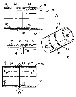
Turning initially to Figs 2A to 3C, there is shown a
deformable member indicated generally by reference numeral
46, in accordance with a first embodiment of the present
invention. The deformable member 46 is shown in Figs 2A to
2C in an undeformed position, and comprises a generally
hollow cylindrical body 48 defining a wall 50 of the member
46. The wall 50 includes three circumferential lines of
weakness in the form of grooves, spaced equidistantly along
the wall 50, with two grooves 52 and 54 provided in an
outer surface 56 of the member wall 50, and the other
groove 58 provided in an inner surface 60 of the member
wall 50. Each of the grooves 52, 54 and 58 are
substantially V-shaped in cross-section and are formed in
CA 02414358 2003-O1-02
WO 02/04783 PCT/GBO1/03072
the deformable member by a finishing process such as a
milling or turning operation.
The deformable member 46 is hollow to allow the member
to be located on a supporting member such as an inner
5 mandrel or sleeve (not shown), to form part of a well tool
or the like for running the deformable member into the
borehole 12 of Fig 1.
Fig 2B is an enlarged view of part of the member wall
50 of the deformable member 46 shown in Fig 2A, and shows
10 the grooves 52, 54 and 58 in more detail. The axially
outermost grooves 52 and 54 define a zone of deformation 62
of the deformable member 46, shown in Fig 2A and, as will
be described with reference to Figs 3A to 3C, deformation
of the deformable member 46 is restricted to the
15 deformation zone 62.
The two grooves 52 and 54 in the outer surface 56 of
the member wall 50 extend into the wall 50 to a depth
approximately equal to half the wall thickness. The other
groove 58 in the inner surface 60, however, extends to a
20 greater depth within the member wall 50 and, as shown in
Fig 2B, ideally extends to a depth greater than half the
wall thickness of the member wall 50.
Turning now to Figs 3A to 3C, the deformable member 46
is shown in the deformed position. The member 46 is
25 deformed in one of a number of fashions. Generally
speaking, there are four generic energising principles for
deforming the member 46. These are the application of an
axial force; the application of an axial force with spring
assist; differential piston area; and relative degrees of
freedom. Of course, a combination of such principles may
be employed for deforming the member 46, and such
principles apply for each of the deformable members
discussed herein.
Considering axial loading, in this case, the member 46
is deformed by application of an axial force in the
CA 02414358 2003-O1-02
WO 02/04783 PCT/GBO1/03072
26
direction of the arrows A shown in Fig 3A. To allow the
deformable member 46 to deform, the member is constructed
from a tough, malleable material which allows the member 46
to deform in the deformation zone 62. Typical suitable
materials may be carbon steel, stainless steel or other
malleable non-ferrous alloys. However, it will be
understood that any other material having suitable material
properties, such as a plastics material, may be selected.
The axial force is exerted upon the member 46 by a
setting tool (not shown), and application of the axial
force in the direction of the arrows A causes the member 46
to fold by deforming in the deformation zone 62, such that
the member wall 50 deforms outwardly.
This deformation is achieved by causing the grooves
52, 54 and 58 to close on application of the axial force,
as shown particularly in Fig 3B, which is an enlarged view
of the member wall 50 in the deformed position. ~nThen
deformed, the member 46 "bulges" outwardly to engage a tube
(not shown) in which the deformable member is located.
Thus the compressive axial loading on the member 46 forces
the expanding portion in the deformation zone 62 into
contact with a mating part of the tube. This load must be
sustained or otherwise retained to ensure continuous
energising of the member 46 in the deformed position. The
expanded portion thus forms a contact with the mating part
of the tube to provide a seal. A conventional type seal
such as an O-ring or T-seal (not shown) is used to seal the
non-expanding portion of the member 46 outside the
deformation zone 62 to the mandrel, as will be described
below.
The outer diameter of the member 46 in the region of
the deformation zone 62 is determined by the axial distance
between the groove 58 in the inner member wall surface 60
and the adjacent grooves 52 and 54 in the outer member wall
surface 56. The member 46 is arranged to deform in an
CA 02414358 2003-O1-02
WO 02/04783 PCT/GBO1/03072
27
outward direction as shown in Fig 3A by the location and
depth of the groove 58, which extends into the member wall
50 to a greater depth than either of the grooves 52 or 54.
It will be understood that this creates a high stress
concentration at a tip 64 of the groove 58 when the axial
force is applied, causing the member 4~ to fold and deform
outwardly. This forms a circumferential edge 66 shown in
Fig 3C, which provides a sharp, circumferential point load
with a tube (not shown) such as a borehole casing in which
the member 46 is located, to provide a high load radial
force and create a good seal between the member 46 and the
tube.
When it is desired to return the member 46 to the
undeformed position of .Fig 2A, it is necessary only to
apply an axial force to the member 46 in the opposite
direction to the arrows A of Fig 3A. This extends the
member 46 and causes the member wall 50 in the region of
the deformation zone 62 to return to the undeformed
position of Fig 2A. It will be appreciated by persons
skilled in the art that, depending upon the selection of
the material for the deformable member 46, the member may
be either plastically or elastically deformable. Where the
member 46 is plastically deformable, the member will remain
in a deformed or .undeformed position until a force is
applied to the member to move it to the other position.
Where the member 46 is elastically deformable, the member
will be resilient and will tend to return to either a
deformed or undeformed position in the absence of an
activating force retaining the member in the desired
position.
The spring assisted energising principle functions in
conjunction with the application of an axial load as
discussed above. A spring (not shown) is provided,
typically a compression type spring, located in line with
the direction of the applied axial load, in the direction
CA 02414358 2003-O1-02
WO 02/04783 PCT/GBO1/03072
28
of the arrows A of Fig 3A. This is beneficial both in
preventing de-energising through a backlash and in
preventing de-energising due to creep. In the case of
preventing de-energising through backlash, the inclusion of
such a spring allows the axial loading on the member 46 to
remain relatively constant in the event that any mechanical
backlash is present in a load-locking,system, such as a
ratchet provided on a bridge plug, as will be described in
more detail below. In the case of preventing de-energising
due to creep, it is considered possible that the member 46
will be subject to additional deformation under the
influence of the failure mechanism known as "creep". In
the event of this occurring, any loss of energising load
experienced due to, for example, shortening of the member
46, will be compensated for by the spring.
The differential piston area and degree of freedom
energising principles will be discussed in more detail with
reference to Figs 30 to 32 below.
The deformable member 46 shown in Figs 2A to 3C has
particular applications in downhole well assemblies as a
static seal; to provide flow control for a borehole or
tubing; and in non-flow type applications.
As a static seal, the deformable member 46 may be
provided as part of a bridge plug, such as the bridge plug
24 of Fig 1 (as will be described in more detail with
reference to Figs 37A to 50E below), a packer such as the
packer 28, an ECP such as the ECP 42, as well as in tool
body connections and pipeline/flow line connections.
To provide flow control, the deformable member 46 may
be provided as part of a variable annular venturi, such as
the venturis 30 and 32 (Fig 1), which provide flow control
in an annular flow area defined between a tube in which the
member 46 is located and the tool and string to which the
member 46 is connected. When the member 46 is in the
undeformed position, fluid flow occurs through a full
CA 02414358 2003-O1-02
WO 02/04783 PCT/GBO1/03072
29
annular flow area; partial deformation to a position
between the undeformed position of Fig 2A and the deformed
position of Fig 3A causes a partial restriction of the flow
area, whereas full deformation of the member 46 to the
position shown in Fig 3A causes full closure of the annular
flow area. Further flow control applications are as an
alternate sliding side door, which operates in a similar
fashion to the venturi 30, 32, with the member 46 provided
within a self-contained ported annular housing (not shown).
The member 46 is deformed between the undeformed and
deformed positions to provide on/off control of flow from
tubing coupled to the member 46 to an external annulus, and
vice-versa.
Non-flow applications of the deformable member 46
include as a wireline sidewall cutter incorporating the
deformable member 46. In this case, the member 46 is
provided as part of a tool located in a casing, together
with a wireline located externally of the member 46, in an
annulus defined between the casing wall and the member 46.
Deformation of the member 46 to the deformed position of
Fig 3A causes the wireline to be crimped or cut against the
wall of the tube. Equally, the member 46 can be provided
within a casing to act as a tubing cutter or crimper. The
high circumferential point load obtained through contact
between the circumferential edge 66 of the member 46 and a
tube acts to crimp or cut the tube when the point load
exceeds the yield point of the tube material.
In a similar fashion, the member 46 can be provided as
part of a tool for obtaining electrical connection through,
for example, a plastics membrane lined tube, wherein, upon
deformation of the member 46 to the deformed position, the
plastics membrane is perforated, to obtain metal to metal
electrical connection through the membrane, between the
member 46 and the tube.
Finally, the member 46 can be used as part of a casing
CA 02414358 2003-O1-02
WO 02/04783 PCT/GBO1/03072
scraper tool, deformed into light contact with, for
example, a casing wall. The member 46 is then reciprocated
within the casing to remove debris from the casing wall.
In a similar fashion, the member 46 can be provided as part
5 of a debris barrier/junk catcher tool, where the member 46
is deformed into light contact with the casing wall. This
provides a barrier against the passage of debris into the
casing below the member.
As discussed above, Figs 4A to 25C; 33A to 34C and 51A
10 to 54B disclose deformable members in accordance with
alternative embodiments of the present invention, similar
to the deformable member 46 of Figs 2A to 3C. For clarity,
only the differences between the deformable members of Figs
4A to 25C and 33A to 34C relative to the deformable member
15 46 of Figs 2A to 3C will be discussed herein. Zike
components of the deformable members of Figs 4A to 25C with
the deformable member 46 and subsequent embodiments share
the same reference numerals, with the addition of the
letters "a", "b", "c" etc, for each new embodiment.
20 Figs 4A to 5C show a deformable member indicated
generally by reference numeral 40a, in accordance with a
second embodiment of the present invention. The grooves
52a and 54a are provided in an inner surface 60a of a wall
50a of the member 46a, and the groove 58a is provided in an
25 outer surface 56a of the member wall 50a. The grooves 52a
and 54a define the zone of deformation 62a of the member
46a. The groove 58a in the member wall outer surface 56a
extends to a depth greater than half the wall 50a
thickness, in a similar fashion to the groove 58 in member
30 46.
In this fashion, when an axial force is applied in the
direction of the arrows A shown in Fig 5A, the member 46a
is deformed inwardly, to engage a tube (not shown) located
within the deformable member 46a. This deformation occurs
in the same fashion as for the deformable member 46 of Figs
CA 02414358 2003-O1-02
WO 02/04783 PCT/GBO1/03072
31
2A to 3C, forming a circumferential edge 66a, shown in Fig
5C, for engaging the tube.
The deformable member 46a has numerous applications in
downhole well assemblies, including as a drilling BOP such
as the BOP 20, a wireline stuffing box such as the stuffing
box/coiled tubing injector head 16, a variable venturi such
as the internal venturi 32, and as a pipe clamp. Other
applications of the member 46a exist as will readily be
understood by persons skilled in the art. However,
generally speaking, it will be understood that the
deformable member 46a provides anchoring/sealing engagement
with a tube located within the hollow member 46a when it is
moved to the deformed position of Figs 5A to 5C.
Figs 6A to 7C show a deformable member indicated
generally by reference numeral 46b, in accordance with a
third embodiment of the present invention. The deformable
member 46b includes two grooves 52b and 54b provided in an
outer surface 56b of a wall 50b of the member 46b, similar
to the grooves 52 and 54 in the member 46. The other line
of weakness defines a channel 68, shown more clearly in the
enlarged view of Fig 6B. The channel 68 has a
substantially flat base 70 with inclined side walls, and is
provided in an inner surface 60b of the member wall 50b.
A further circumferential groove 74, substantially V-shaped
in cross section, similar to the grooves 52, 54 and 58 of
member 46, is provided in the flat base 70 of the channel
68.
When the member 46b is deformed on application of an
axial force A, shown in Fig 7A, the profile of the channel
68 causes a lip 77, best shown in Figs 7B to 7D, to be
formed at a radially outer extreme of the member 46b, in
the region of the deformation zone 62b. The lip 76 is of
an outer diameter greater than the major expansion of the
deformable member 46b. The lip 76 is relatively soft and
deformable, and has particular advantages in allowing the
CA 02414358 2003-O1-02
WO 02/04783 PCT/GBO1/03072
32
member 46b to be located in an ovalised or damaged tube or
other bore, as well as providing a seal activated by a low
actuating energy, for use in low pressure environments,
and/or to provide a gas-tight seal with a tube or bore.
This is achieved due to deformation of the Zip 76 of the
member 46b on contact with the tube or bore in which the
member is located, when moved to the deformed position of
Figs 7A to 7D.
The deformable member 46b has particular applications
in downhole well assemblies as an ECP such as the ECP 42,
a bridge plug, such as the bridge plug 24 shown in Fig 1
(as will be described in more detail with reference to Figs
37A to 50E below), as well as a packer such as the packer
28.
Figs 8A to 9C show a deformable member indicated
generally by reference numeral 46c, in accordance with a
fourth embodiment of the present invention. The member 46c
is similar to the member 46b of Figs 6A to 7D, and includes
two grooves 52c and 54c provided in an outer surface 56c of
a wall 50c of the member 46c. Also, a channel 68c is
defined in an inner surface 60c of the member wall 50c,
similar to the channel 68 of Fig 6A.
The channel 68c, as shown in Fig 8B, includes a
substantially flat base 70c with inclined side walls 72c.
Two circumferentially extending grooves 74c are provided in
the flat base 70c of the channel 68c, and the grooves 74c
are connected by a curved portion 78 of the inner wall
surface 60c.
When the member 46c is moved to the deformed position,
shown in Figs 9A to 9C, by application of an axial force in
the direction A (Fig 9A), the member 46c is deformed in the
deformation zone 62c, and the curved wall portion 78 is
deformed outwardly to define a rounded lip 80, best shown
in the enlarged view of Fig 9B and the perspective view of
Fig 9C.
CA 02414358 2003-O1-02
WO 02/04783 PCT/GBO1/03072
33
The deformable member 46c has particular applications
similar to those of the member 46b of Figs 6A to 7C.
However, in addition, the member 46c may be suitable for
dynamic applications, such as to provide flow control for
a borehole or tubing, similar to the deformable member 46
of Figs 2A to 3C.
Figs 10A to 11C show a defo-rmable member indicated
generally by reference numeral 46d, in accordance with a
fifth embodiment of the present invention. The member 46d
is substantially identical to the member 46 of Figs 2A to
3C. However, the member 46d includes two upstanding ribs
82 and 84 on an outer surface 56d of the member 46d. The
ribs 82 and 84 are provided in the region of the
deformation zone 62d, and are axially spaced either side of
a groove 58d in an inner surface 60d of the member wall
50d, and are inclined towards one another. Each rib 82 and
84 is substantially V-shaped in cross-section, such that,
when the member 46d is moved to the deformed position of
Figs 11A to 11C, by application of an axial force in the
direction A (Fig 11A), the ribs 82 and 84 engage and
penetrate the wall of a tube in which the member 46d is
located.
The application of further axial force on the member
46d causes the ribs 82 and 84 to further penetrate and
engage the wall of the tube, thus further energising the
anchoring/sealing effect of the member 46d. This is due to
the fact that the ribs 82 and 84 are provided in the
deformation zone 62d, and are therefore angled into the
tube wall when deformed, as shown particularly in Figs 11B
and 11D.
The deformable member 46d has particular applications
as a bridge plug, such as the bridge plug 24 of Fig 1 (as
will be described below with reference to Figs 37A to 50E),
as a packer such as the packer 28, and generally as a tool
body connection and pipeline/flowline connections.
CA 02414358 2003-O1-02
WO 02/04783 PCT/GBO1/03072
34
Figs 12A to 13C show a deformable member indicated
generally by reference numeral 46e, in accordance with a
sixth embodiment of the present invention. The member 46e
includes four lines of weakness in the form of grooves 52e
and 54e in an outer surface 56e of the member wall 50e, and
grooves 86 and 88 in an inner surface 60e of the member
wall 50e.
The grooves 86 and 88 are similar to the groove 58 in
the member 46 of Figs 2A to 3C and extend into the member
wall 50e to a depth greater than half the wall thickness,
as shown in particular in the enlarged view of Fig 12B. An
outer portion 90 of the wall 50e is defined between the
grooves 86 and 88 in the inner wall surface 60e. The
grooves 86 and 88 and the wall portion 90 are such that,
when the member 46e is moved to the deformed position shown
in Figs 13A to 13C, on application of an axial force in the
direction A (Fig 13A), the member 46e is deformed in the
deformation zones 62e, and bulges outwardly, such that the
wall portion 90 engages a tube in which the member 46e is
located. This spreads the force exerted on the tube over
a greater surface area, reducing the likelihood of damage
to the tube.
Furthermore, the wall portion 90 can be laminated with
a sealing material (not shown) such as Nitrite, Viton, or
Teflon (trade marks), to provide a gas-tight seal with the
tube, whereby sealing is achieved with a relatively low
energising force. This provides a high-pressure and high-
temperature sealing capability of the member 46e. In an
alternative embodiment the member 46e is laminated with a
relatively soft metal material (not shown), to provide a
metal to metal seal at a relatively low energising force.
The deformable member 46e has particular applications
as a bridge plug, such as the bridge plug 24 (as will be
described below with reference to Figs 37A to 50E), as a
packer such as the packer 28, a liner hanger such as the
CA 02414358 2003-O1-02
WO 02/04783 PCT/GBO1/03072
hanger 38, or as an anchor system. Also, the deformable
member 46e may have dynamic applications such as for
providing flow control through borehole or tubing, in a
similar fashion to the member 46 of Figs 2A to 3C.
5 Figs 14A to 15C show a deformable member indicated
generally by reference numeral 46f, in accordance with a
seventh embodiment of the present invention. The member
4 6f is similar to the member 46e of Figs 12A to 13C . A
wall portion 90f of the member 46f, shown in particular in
10 the enlarged view of Fig 14B, includes a circumferential
groove 92 which carries a seal, such as a plastics or
elastomeric seal, to improve sealing with a tube in which
the member 46f is located, when moved to the deformed
position of Figs 15A to 15C.
15 Figs 16A to 17C shows a deformable member indicated
generally by reference numeral 46g, in accordance with an
eighth embodiment of the present invention. The member 46g
is similar to the member 46e of Figs 12A to 13C, and a
portion 90g of member wall 50g carries a plurality of
20 ridges 94, shown in particular in the enlarged view of Fig
16B. The ridges 94 extend around the circumference of the
portion 90g as shown in Fig 16C, and are either a simple
screw thread, or individual circumferentially extending
ridges.
25 The deformable member 46g has general applications as
an anchor and/or a seal with multiple point contact with a
tube in which the member 46g is located. The ridges 94
penetrate the tube to fix the member 46g in position. The
member 46g has particular applications as a bridge plug,
30 such as the bridge plug 24 (as will be described with
reference to Figs 37A to 50E below), a packer such as the
packer 28, a liner hanger such as the liner hanger 38, or
as an anchor system.
Figs 18A to 19C show a deformable member indicated
35 generally by reference numeral 46h, in accordance with a
CA 02414358 2003-O1-02
WO 02/04783 PCT/GBO1/03072
36
ninth embodiment of the present invention. The member 46h
is similar to the member 46 of Figs 2A to 3C in that it
includes two grooves 52h and 54h in an outer surface 56h of
a member wall 50h, and a groove 58h in an inner surface 60h
of the member wall 50h. However, the groove 58h is axially
closer to the groove 52h than the groove 54h. This is
shown in particular in the enlarged view of Fig 18B.
When moved to the deformed position of Figs 19A to
19C, this causes the member 46h to deform in the
deformation zone 62h. in the fashion shown in Fig 19B, non
symmetrically about groove 58h. This provides an
energising load bias. under pressure, as will be described
in more detail below with reference to Figs 31 and 32,
with greater deformation taking place in a longer portion
96 of the member 46h.
The deformable member 46h has particular applications
in the same area as the deformable member 46 of Figs 2A to
3C.
Figs 20A to 21D show a deformable member indicated
generally by reference numeral 46i, in accordance with a
tenth embodiment of the present invention. The member 46i
includes two grooves 52i and 54i provided in an outer
surface 56i of the member wall 50i, and two grooves 98 and
100 formed in an inner surface 60i of the member 50i. The
grooves 52i, 98, 54i and 100 are provided alternately in
the outer and inner wall surfaces 56i and 60i respectively,
along the length of the member 46i. The grooves 98 and 100
are similar to the groove 58 of the member 46 shown in Figs
2A to 3C, and extend into the wall 50i to a depth greater
than half the wall thickness. When the member 46i is moved
to the deformed position of Figs 21A to 21D, on application
of an axial force in the direction of the arrows A (Fig
21A), the member deforms in the deformation zone 62i both
inwardly and outwardly, as best shown in the enlarged view
of Fig 21B.
CA 02414358 2003-O1-02
WO 02/04783 PCT/GBO1/03072
37
This forms an outer circumferential edge 66i for
engaging a tube in which the member 46i is located, and an
inner circumferential edge 102, for engaging a tube located
within the hollow member 46i.
The member 46i has particular applications similar to
those of the member 46 of Figs 2A to 3C and the member 46a
of Figs 4A to 5C, in combination.
Figs 22A to 23E show a deformable member indicated
generally by reference numeral 46j, in accordance with an
eleventh embodiment of the present invention. The member
4~j is similar to the member 46i of Figs 20A to 21D, except
that it includes five lines of weakness, with an additional
groove 104 provided in an outer surface 56j of member wall
50j. This provides two circumferential edges 106 and 108
in the outer wall surface 56j when the member 46j is moved
to the deformed position of Figs 23A to 23D. This affords
improved contact with a tube in which the member 46j is
located, together with engagement with a tube located in
the member 46j, through contact with an edge 102j in the
inner wall surface 60j. The deformable member 46j has
applications similar to the member 46i of Figs 20A to 21D,
including the above-noted advantages.
Figs 24A to 25C show a deformable member indicated
generally by reference numeral 46k, in accordance with a
twelfth embodiment of the present invention. The
deformable member 46k operates to move between deformed and
undeformed positions in a similar fashion to the deformable
members of Figs 2A to 23D, but is of a different
structure, as will be described herein:
The deformable member 46k comprises a body having a
first generally hollow cylindrical portion 110 and a second
hollow bulbous portion 112. The hollow cylindrical portion
110 has a member wall 114 of a first general wall
thickness, and the bulbous portion 112 has a wall 116 which
varies in thickness to a minimum wall thickness at the area
CA 02414358 2003-O1-02
WO 02/04783 PCT/GBO1/03072
38
113 where the outside diameter of the bulbous portion 112
is greatest.
The difference in the wall thickness between the
hollow cylindrical portion 110 and the bulbous portion 112
is shown in particular in the enlarged view of Fig 24B.
Figs 25A to 25C show the deformable member 46k when it
has been moved to the deformed position, on application of
an axial force in the direction of the arrows A, shown in
Fig 25A, in similar fashion to the deformable members of
Figs 2A to 23D. Application of the axial force compresses
the bulbous portion 112, which deforms and "bulges"
outwardly, in a similar fashion to the portion of the
deformable member 46, in the deformation zone 62. This
brings an outer surface 118 of the bulbous portion 112 into
contact with a tube in which the member 46k is located for
anchoring and/or sealing engagement therewith.
The rounded nature of the bulbous portion 112 ensures
that a soft, rounded contact is obtained between the outer
surface 118 and the tube, and provides a progressive,
distributed load, ensuring that high stress-concentration
nodes do not form in the member 46k on deformation. The
member 46k is generally suited to cyclical expansion
applications, and has particular applications in downhole
well assemblies as a dynamic metal to metal seal, such as
used in reciprocating pistons or tubing expansion joints;
as an interference fit seal using smooth leading edges of
the bulbous portion 112 to provide a press-fit into a tube
or seal bore; as tool body connections, PBR seals such as
the PBR 36, or as lubricator quick connect seals; and as a
non-penetrating, non-damaging seal for, in particular,
plastic coated tubes or materials suspectable to corrosion
cell formation through a damaged passive layer.
Figs 26A to 27B show a deformable member indicated
generally by reference numeral 461 in accordance with a
thirteenth embodiment of the present invention. The
CA 02414358 2003-O1-02
WO 02/04783 PCT/GBO1/03072
39
deformable member 461 is the most structurally simple form
of deformable member according to the present invention.
The member 461 comprises a hollow cylindrical body 481,
which is shown in Figs 26A and 26B in an undeformed
position.
Figs 27A to 27C show the deformable member 461 in a
deformed position, following application of an axial force
in the direction of the arrows A of Fig 27A. This causes
the wall 501 of the body 481 to deform to form a ring 282
of material, shown in particular in Fig 27C, upstanding
from the outer surface 561 of the member 461. In a similar
fashion to the above described embodiments, this provides
sealing with a tube or the like in which the member 461 is
located.
Figs 28A to 29C show a deformable member indicated
generally by reference numeral 46m, in accordance with a
fourteenth embodiment of the present invention. The
deformable member 46m operates to move between deformed and
undeformed positions in a similar fashion to the deformable
members of Figs 2A to 23D, but is of a structure similar to
that of the member 46k shown in Figs 24A to 25C.
The deformable member 46m comprises a body having a
first generally hollow cylindrical portion 110m and a
second hollow portion 112m. The hollow cylindrical portion
110m has a member wall 114m of a first general wall
thickness, with two circumferentially extending lines of
weakness in the form of generally rectangular section
grooves 284 and 286, provided in an outer surface 288 of
the portion 114m. The hollow portion 112m has a wall 116m
which is of a wall thickness less than that of the wall
114m, and thus a portion of the member wall is defined
between the grooves 284 and 286.
The member wall 114m defines shoulders 290, 292 which
both support the hollow portion 112m, to constrain
deformation of the wall 116m, and allow for transferral of
CA 02414358 2003-O1-02
WO 02/04783 PCT/GBO1/03072
the axial force to the portion 112m. Also, the member 46m
includes internal seal carrying channels 294 for carrying
seals such as an elastomeric O-ring seal, for sealing to a
mandrel or the like carrying the member. As will be
5 discussed in more detail with reference to Figs 30 to 32,
a chamber 296 is defined between the portions 110m and 112m
of the member 46m and the carrying mandrel. This chamber
296 selectively assists in deforming the member 46m to the
deformed position of Figs 29A to 29C.
10 T h a memb a r ~'~~n--rs ~-l~rcr-w n---i-r~-F ~_ g~~-- ~ i-n a
deformed position, on application of an axial force in the
direction of the arrows A of Fig 29A, in a similar fashion
to the above described embodiments of the invention.
It will be noted that the wall 11~m, on application of
15 the axial force, deforms and bulges outwardly, to bring an
outer surface 118m of the wall 116m into contact with a
tube or the like in which the member 46m is located. To
allow for this deformation, the grooves 284 and 286 become
closed, as shown in particular in Fig 29B.
20 Referring now to Fig 30, which is a view of the member
46m in use, shown in the deformed position of Fig 29A, the
member 46m is shown located on a mandrel 298 and is sealed
to the mandrel 298 by 0-ring rubber seals 300, located in
the seal carrying channels 294. In this position, the
25 surface 118m of the portion 116m has been brought into
contact with an inner surface 302 of a tube such as a
casing 304 in which the member 46m is located. As noted
above, the member 46m can be moved to the deformed position
shown on application of an axial force. As shown in Fig
30 30, a force F1 can be exerted on sleeve end portions 306
and 308 of the member 46m to move it to the deformed
position.
However, the member 46m may also be moved to the
deformed position by fluid pressure, due to the
35 differential piston area of the member 46m in use, as shown
CA 02414358 2003-O1-02
WO 02/04783 PCT/GBO1/03072
41
and described briefly above. Differential pressure forces
are exerted upon the member 46m due to the pressures P1 and
P2 of fluid in the annulus 310 above and below the member
46m.
The differential piston area is the cross-sectional
area of the annulus 310, and is determined according to the
following calculation:
n/4 (D22 - D1z)
' where Dl and D2 are, as shown, the outer and inner
diameters of the mandrel 298 and the casing 304,
respectively. From this, we obtain the pressure force f
due to the pressure P1, which is equal to pressure times
area, as:
f = P2 x n/4 (D2z - D12)
It will be understood that the force due to the pressure P2
is calculated in a similar fashion. The differential
piston area may therefore allow a fluid pressure force to
be exerted on the member 46m, to move it to the deformed
position. However, the differential piston force may also
Sae utilised in conjunction with application of an axial
force F1 to maintain the member 46m in the deformed
position.
Referring now to Fig 31, the member 46m is shown in
the deformed position of Fig 29A and mounted on a mandrel
312 similar to the mandrel 298 of Fig 30, except including
a pressure vent port 314. The pressure vent port 3l4
provides fluid communication between the chamber 296 and an
inner annulus 316 of the mandrel 312. This allows the
member 46m to be deformed by differential pressure across
the member 46m, between the chamber 296 and the annulus
310. Thus fluid pressure P3 in the annulus 316, acting
through the port 314, without the need for axial loading F1
(or fluid pressure loading P1 or P2) acts to deform the
member 46m, where P3 is greater than the annulus pressure.
However, in the event that an axial load F1 is used to move
CA 02414358 2003-O1-02
WO 02/04783 PCT/GBO1/03072
42
the member 46m to the deformed position, pressure P3 may be
used as a back-up energising method, to maintain
deformation of the member 46m.
Referring now to Fig 32, there is shown a deformable
member similar to the member 46m, indicated generally by
reference numeral 46n. The structure of the member 46n is
identical to that of the member 46m except that only a
single seal 300n is provided, and that a pressure vent port
318 is provided in the wall 114n of the portion 110n of
member 46n. This provides fluid communication between the
annulus 310 and the chamber 296n of the member 46n and
allows the member 46n to be deformed by fluid pressure
through the annulus 310, and vent 318 to the chamber 296n.
Of course, it will be understood that in a similar fashion
to the embodiment of Figs 30 and 31, the member 46n may be
deformed by application of axial force F1, or by a
combination of axial force F1 and pressure P1.
Figs 33A to 34C show a deformable member indicated
generally by reference numeral 46p, in accordance with a
fifteenth embodiment of the present invention. The
deformable member 46p is similar to the member 461 of Figs
26A to 27B, in that it includes a generally hollow
cylindrical body. However, the member 46p differs in that
end portions 320 and 322 of the member 46p have a wall
thickness which is greater than a wall thickness of the
body 48p in a deformation zone 62p of the member. Also,
the wall 50p in the region of the deformation zone 62p is
preformed into a shape which encourages the member 46p to
deform outwardly, in the fashion shown in Figs 34A to 34C.
Also, a deformation aid in the form of a plastios or
rubber O-ring is provided within the body 48p at a midpoint
326 of the deformation zone 62p. As shown in particular in
Fig 34C, when the member 46p is deformed, for example, on
application of an axial force A, shown in Fig 34A, the wall
50p of the body 48p in the region of the deformation zone
CA 02414358 2003-O1-02
WO 02/04783 PCT/GBO1/03072
43
62p deforms around and compresses the O-ring 324. This
forms a ring 282p of material for engaging the wall of a
tube or the like in which the member 46p is located. It
will therefore be understood that the inclusion of the O-
ring 324 assists in obtaining the desired deformation of a
plain body such as that of the member 46p.
Referring now to Figs 35A and 35B, there are shown
deformable members indicated generally by reference numeral
46q, acting as anti-extrusion seals to prevent extrusion of
a conventional seal 328 in use. The seal 328 receives ends
330 of the members 46q, which abut a radial shoulder 332 of
the seal 328. The members 46q are disposed such that
respective grooves 54 of each member 46q are located
outside the seal 328 adjacent to faces 334 of the seal 328.
As will be understood by persons skilled in the art,
the seal 328 is of the type conventionally used for
obtaining sealing in a tube, such as the casing 336 shown
in Fig 35B, which is a view of the seal 328 and members 46q
in use, with the members 46q moved to a deformed position.
Conventionally, such seals 328 are mounted on mandrels
carrying anti-extrusion rings (not shown). However, the
seals 328 are of an expandable plastics or rubber material,
which is deformed into engagement with an inner wall 338 of
the casing 336 to provide sealing. As the anti-extrusion
rings are not similarly expandable, an annular gap (not
shown) exists between the rings and the casing wall 338.
Differential pressure across the seal 328 through such an
annular gap tends to cause extrusion of the seal 328 and
ultimately results in seal failure.
To overcome this, provision of the members 46q, and
deformation of the members to the position shown in Fig
35B, in the fashion described above, brings the members
into engagement with the casing wall 338, closing the
annular gap and protecting the seal 328 from extrusion.
Figs 36A and 36B illustrate a collapse aid 340 for a
CA 02414358 2003-O1-02
WO 02/04783 PCT/GBO1/03072
44
deformable member, in this case, the member 46 of Figs 2A
to 3C. The collapse aid 340 is provided to assist in
returning the deformable member 46 from the deformed
position shown in Fig 36A, to the undeformed position of
Fig 36B. The collapse aid 340 is in the form of a sleeve,
typically known as an extrusion cone, and has a bevelled
leading edge 342. The collapse aid 340 is run downhole to
the location of the deformable member 46, and is run over
the member 46 as shown in Fig 36A. The bevelled edge 342
is then brought into abutment with the member 46 in the
deformation zone 62, contacting a face 344 of the member
46. This, together with application of a tensile load in
the direction of the arrows B, assists in returning the
member 46 to the undeformed position.
The provision of the collapse aid 340 is particularly
advantageous in that it avoids the requirement for very
high tensile loading to be applied through the deformation
zone 62 of the member 46 to recover the member to the
undeformed position. This is particularly useful as in
certain situations, the high stress applied to the member
4~ during movement to the deformed position of Fig 36A can
cause permanent damage, preventing full retraction to the
undeformed position.
As noted above, for each of the deformable members 46
to 46q described above, an alternative fashion of moving
the members between deformed and undeformed positions is to
provide relative degrees of freedom. For example, either
end of one of the members may be fixed relative to, for
example, a carrying mandrel, in particular to limit the
effect of differential pressure forces due to the
differential piston area encountered, as described above
with reference to Figs 30 to 32 in particular. In such
situations, where relatively high pressures are
encountered, it may not be desirable to load the members to
the full extent of the potential differential piston
CA 02414358 2003-O1-02
WO 02/04783 PCT/GBO1/03072
loading, as this may exceed the design capabilities of the
material of the members, and cause failure.
Restraining one end of the members from movement
towards the opposite end ensures that differential piston
5 loading applied from the constrained end does not further
energise the seal, preventing further deformation and seal
failure under extreme pressure.
Referring now to Figs 37A to 47B, there are shown
various views of a bridge plug indicated generally by
10 reference numeral 120, in accordance with a first
embodiment of the present invention, and including the
deformable member 46 of Figs 2A - 3C. However, it will be
appreciated by persons skilled in the art that the bridge
plug 120 may equally include a deformable member in
15 accordance with any of the second to twelfth and further
embodiments of the present invention described above with
reference to Figs 4A-25C; 33A-34B; and 51A-54B below.
Turning initially to Figs 37A and 37B, there are shown
longitudinally sectioned perspective and longitudinal
20 sectional views, respectively, of the bridge plug 120,
shown in a running position where the deformable member 46
is in the undeformed position of Figs 2A to 2C.
A bridge plug is generally used in downhole situations
where, for example, pressure isolation and testing is
25 required or a casing or lining installed in a borehole has
become corroded, perforated or otherwise damaged, allowing
ingress of non-well fluids, sand and other materials
detrimental to the retrieval of well fluids through the
borehole. The bridge plug isolates the damaged portion of
30 the casing, and allows fluid communication from a location
below the bridge plug to above the bridge plug, allowing
well production to continue and permitting the access of
well tools into the borehole, whilst isolating the non-well
fluids, sand and the like from the remainder of the casing.
35 Bridge plugs are typically run into a borehole as part of
CA 02414358 2003-O1-02
WO 02/04783 PCT/GBO1/03072
46
a tool string, to a depth where the bridge plug is required
to be located or "set" in the ca sing.
The bridge plug 120 of Figs 37A and 37B is run-into a
borehole as part of such a tool string, and includes a
setting tool (not shown), coupled to the bridge plug 120 at
an end 122, which is the upper end of the bridge plug in
use, when run into the borehole. The bridge plug 120
generally comprises the upper end 122, which includes a
"fish neck" profile 124, to allow retrieval of the tool, a
ratchet mechanism 126, a seal 46 in the form of the
deformable member, a slip mechanism 128 and an end 130
which forms the lower end of the bridge plug 120 when it is
run into the borehole, and which includes a set/unset
profile 132. The bridge' plug 120 is shown in Fig 37B in
the upright position in which it is run into the borehole.
Each of the separate components of the bridge plug 120 will
be described in more detail with reference to Figs 38A to
47B below.
Figs 38A and 38B are enlarged views of the bridge plug
120 showing the upper and lower parts of the plug,
respectively.
The upper end 122 of the bridge plug 120 comprises a
tubular fish-neck sleeve 134, coupled to the ratchet
mechanism 126 by a transfer sleeve 136, which is secured to
the fish-neck sleeve 134 by a threaded connection 137,
secured using locking screws 138. The transfer sleeve 136
is coupled to the ratchet mechanism 126 via shear screws,
twa of which are shown and given the reference numeral 140.
The ratchet mechanism 126 will be described in more detail
with reference to Figs 39A and 39B below. However, the
ratchet mechanism 126 is connected to the seal 46, and both
the ratchet mechanism 126 and the seal 46 are mounted on an
inner sleeve 142 of the bridge plug 120, which extends to
the end 130 and carries the set/unset profile 132. The
slip mechanism 128 is mounted on the inner sleeve 142 below
CA 02414358 2003-O1-02
WO 02/04783 PCT/GBO1/03072
47
the seal 46, and the seal 46 is coupled to part of the slip
mechanism 128. The slip mechanism 128 will be described in
more detail with reference to Figs 41A and 41B below.
Turning now to Figs 39A and 39B, there are shown
enlarged views of the ratchet mechanism 126, and
perspective views of segments of the ratchet mechanism,
respectively. The ratchet mechanism 126 includes an upper
sleeve 144, coupled to the transfer sleeve 136 by the shear
screws 140; a release sleeve 146, coupled also to the
transfer sleeve 136 by a threaded connection 147, secured
using locking screws 148 (one shown); a ratchet segment 150
carrying ratchet teeth 152 for engaging corresponding teeth
on the inner sleeve 142; and a shaped ratchet reverse
segment 154. A number of ratchet segments 150 and ratchet
reverse segments 154 are provided spaced around the bridge
plug 120, although only two~are shown in the drawings. Fig
39B shows a ratchet segment 150 and a ratchet reverse
segment 154 in more detail. It will be seen that the
ratchet segment 150 is generally arcuate, and has a curved
face 156 for co-operating with a corresponding curved face
158 of the ratchet reverse segment 154. As will be
described in more detail below, co-operation between the
ratchet teeth 152 on the ratchet segment 150 and the
corresponding teeth on the inner sleeve 142 acts to
restrain movement of the bridge plug when it is moved to a
set position and the seal 46 is deformed. The ratchet
segments 150 are normally retained in engagement with the
inner sleeve ratchet teeth by a shoulder 202 of release
sleeve 146.
Fig 40 is an enlarged view of the seal 46, and it will
be noted that the seal 46 similar to the deformable member
shown in Fig 2A and described above. However, the seal
body 48 includes shoulders 160 and 162 at either end of the
body, the end 160 carrying an elastomeric O-ring seal 164
for sealing an upper end of the seal 46 to the inner sleeve
CA 02414358 2003-O1-02
WO 02/04783 PCT/GBO1/03072
48
142. A lower end of the seal 46 remains unsealed with the
inner sleeve 142, to allow pressure equalisation between an
annular cavity 204 and the remainder of the plug 120.
Referring now to Figs 41A and 41B, there are shown
exploded perspective and perspective views, respectively,
of the slip mechanism 128. The slip mechanism 128 includes
a dynamic slip mandrel 166, a static slip mandrel 168, and
a number of slips 170, only one of which is shown in Fig
41A. The slip mechanism is of a type known in the art,
each of the dynamic and static slip mandrels 166 and 168
including a plurality of segments 172 disposed around the
mandrels. Adjacent pairs of segments 172 together define
uplift ramps 174 and collapse ramps 176. Each slip 170
includes an arcuate body portion 178 carrying slip teeth
180, with. generally T-shaped segments 182 formed at either
end of the body portion 178. The body portion 170 defines
uplift ramps 184 and the T-shaped segments define collapse
ramps 186. When the slip mechanism 128 is assembled, as
shown in Fig 41B, uplift ramps 174 abut the corresponding
uplift ramps 184 of the slips 170, and the collapse ramps
176 of the mandrels 166 and 168 abut the corresponding
collapse ramps 186 of the slips 170. This allows the slips
to be moved radially outwardly to engage a casing wall in
which the bridge plug 120 is located, as will be described
in more detail below.
Referring now to Fig 42, there is shown an enlarged
view of the end 130 of the bridge plug 120. The set/unset
profile 132 includes a connection thread 188 which serves
for connecting the bridge plug 120 to part of the setting
tool, and an elastomeric O-ring seal (not shown) located in
a groove 190. In addition, the end 130 carries an internal
radially extending shoulder 192 which has a lower face 194,
which co-operates with a shear-ring of the setting tool, to
allow the bridge plug 120 to be compressed to set the
plug; and a no-go shoulder 196 to allow the bridge plug 120
CA 02414358 2003-O1-02
WO 02/04783 PCT/GBO1/03072
49
to be axially extended for un-setting the plug.
There follows a description of the method of setting
and un-setting the bridge plug 120. The plug 120 is held
in the extended, unset position of Figs 37A and 37B by
restraining the plug 120 between the fish-neck 124 and the
set/unset profile 132. Co-operation between the collapse
ramps 176 of the mandrel segments 172 and the collapse
ramps 186 of the slips 170 ensures that the slips 170 are
fully retracted. This allows the bridge plug 120 to be run
into the borehole casing in the running position of Figs
37A and 37B.
When the bridge plug 120 has been located at a desired
depth in the borehole casing, the setting tool (not shown)
is initiated. The setting tool axially compresses the
bridge plug 120 between fish-neck 124 and set/unset profile
132, moving the fish-neck sleeve 134 downwards. This
downward movement is transferred to the dynamic slip
mandrel 166 of the slip mechanism 128 through the transfer
sleeve 136, ratchet mechanism 126 and the seal 46, which
initially remains in the undeformed position of Figs 37A
and 37B. Downward movement of the dynamic slip mandrel 166
towards the static slip mandrel 168 forces the slips 170 up
the uplift ramps 174 of the mandrels. This moves the slips
170 radially outwardly, by co-operation with the slip
uplift ramps 184, until they are fully engaged in the
casing wall and cannot expand further.
Once the dynamic slip mandrel 166 has ceased to move
axially, compressive axial loading on the bridge plug 120
is transferred to the seal 46. A predetermined load is
applied which fully energises the seal 46 to move it to the
deformed position, where it expands into contact with the
casing wall, as described above. The bridge plug is
therefore now in the position shown in Figs 43A and 43B,
with the seal 46 and slips 170 fully expanded, as shown in
Figs 44 and Figs 45A and 45B, respectively.
CA 02414358 2003-O1-02
WO 02/04783 PCT/GBO1/03072
As the seal 46 is axially compressed, its axial travel
is secured and locked by the ratchet mechanism 126, by co-
operation between the ratchet teeth 152 of the ratchet
segment 150 and the corresponding teeth on the inner sleeve
5 242. This ensures that the load applied to both the seal
46 and the slips 170 is retained, and securely holds the
bridge plug 120 in the casing in the set position shown in
Figs 43A and 43B.
Having knowledge of the compressive load required to
10 move the bridge plug 120 to the set position allows a
predetermined shear-rated ring or release mechanism (not
shown) on the setting tool to disengage from the shoulder
192 of the set/unset profile 132. This ensures that the
setting tool automatically releases from the bridge plug
15 120 when sufficient force has been applied to set the plug,
and ensures that the setting tool cannot apply a load too
great for the plug 120, which would otherwise cause damage.
When the shear-ring has released the setting tool from the
bridge plug 120, the setting tool is withdrawn and
20 ~ retrieved to surface. Pressure loading on the bridge plug
120 from above or below acts to further compress and engage
both the slip mechanism 128 and the seal 46 with the casing
wall, to further enhance pressure retaining performance of
the bridge plug 120.
25 Referring now to Figs 46A and 47A, the bridge plug 120
is shown after having been returned from the set position
of Figs 43A and 43B, to allow retrieval of the bridge plug
120 after it has carried out the required well operation.
The bridge plug 120 is retrieved from the set position
30 of Figs 43A and 43B by coupling a retrieval tool (not
shown) to the bridge plug 120 and latching it to the fish
neck profile 124. The retrieval tool generates a force
which extends the bridge plug 120 between the fish-neck
profile 124 and the set/unset profile 132. It is important
35 to note that the bridge plug 120 is extended from the set
CA 02414358 2003-O1-02
WO 02/04783 PCT/GBO1/03072
51
position independently of the slips 170. The bridge plug
120 is therefore not dependent upon engagement of the slips
170 with the casing wall to allow retrieval.
Extending the plug 120 shears the shear screws 140
into parts 198 and 200, allowing axial movement of the
transfer sleeve 136 relative to the upper sleeve 144 of the
ratchet mechanism 126, carrying the ratchet release sleeve
146 therewith.
Axial movement of the release sleeve 146 de-supports
the ratchet segments 150, which are normally restrained
from radial movement by the shoulder 202 of the release
sleeve 146 and the shaped ratchet reverse segments 154.
Cn7hen the ratchet segments 150 are de-supported, as shown in
the enlarged view of Fig 46B, the ratchet segments 150 and
the ratchet reverse segments 154 moue radially outwardly,
such that the ratchet teeth 152 disengage from the
corresponding teeth on the inner sleeve 142. This allows
the shoulder 160 of the seal 46 to move axially towards the
fish-neck sleeve 134, to move the seal 46 to the undeformed
position.
Further axial extension of the bridge plug 120
releases the slips 170 from the casing wall, by an
interaction between the collapse ramps 176 of the mandrels
166, 168, and the collapse ramps 186 of the slips 170.
Full extension of the bridge plug 120 to the position shown
in Fig 46A causes full retraction of the seal 46 and slips
170. The bridge plug 120 may then be retrieved to surface.
Referring now to Figs 48A and 48B, there are shown
longitudinally sectioned perspective and longitudinal
sectional views, respectively, of a bridge plug indicated
generally by reference numeral 120a, in accordance with a
second embodiment of the present invention. Like
components of the bridge plug 120a with the bridge plug 120
of Fig 37A share the same reference numerals, with the
addition of the letter "a". The bridge plug 120a includes
CA 02414358 2003-O1-02
WO 02/04783 PCT/GBO1/03072
52
a seal 46a, similar to the deformable member 46 of Figs 2A
to 3C and the bridge plug 120a is shown in Fig 48A and 48B
in a running position, similar to that of the bridge plug
120 shown in Figs 37A and 37B.
The bridge plug 120a is shown in more detail in the
enlarged views of the upper and lower portions of the
bridge plug shown in Figs 48C and 48D. The plug generally
comprises an upper end 122a with fish-neck profile 124a, a
locking key mechanism 206 (shown in Figs 49A and 49B and
described below), a slip mechanism 128a (shown in Fig 49C),
the seal 46a, a retractable ratchet mechanism 208 (shown in
more detail in Figs 49D, 50B and 50C and described below),
a transfer key mechanism 210 (shown in Figs 49E, 50D and
50E and described below), and a lower end 130a, for
coupling to a shear-ring mechanism of a setting tool. The
bridge plug 120a is run into the casing of the borehole on
a setting tool, in a similar fashion to the bridge plug 120
of Fig 37A.
Referring now to Figs 49A to 50E, there are shown
enlarged and perspective views of the locking key mechanism
206; and perspective views of the slip mechanism 128a,
retractable ratchet mechanism 208 and transfer key
mechanism 210, respectively.
Turning initially to Figs 49A and 49B, the locking key
mechanism 206 allows the bridge plug 120a to be returned to
an unset position after having been set, as will be
described below. The key mechanism 206 includes a release
sleeve formed by the outer sleeve 218, and release keys 222
(two shown) located in apertures 224 of an inner sleeve 226
of the key mechanism 206. Each release key 222 defines an
internal shoulder 228 which engages in a recess 230 of
inner plug sleeve 216, to restrain the plug 120a in a set
position, as will be described below. A radially inner
shoulder 232 of the outer sleeve 218 normally retains the
release keys 222 in the apertures 234, such that the key
CA 02414358 2003-O1-02
WO 02/04783 PCT/GBO1/03072
53
shoulder 228 abuts a face 234 of the recess 230, to
restrain the inner sleeve 226 relative to the inner plug
sleeve 216.
The slip mechanism 128a shown in Figs 48C and 49C
differs from the mechanism 128 of bridge plug 120 in that
it includes a slip locking ratchet 212 having a ratchet
segment 214, which carries internal ratchet teeth, for
engaging corresponding teeth on the inner sleeve 216 of the
bridge plug 120a. The ratchet segment 214 is carried by
the dynamic slip mandrel 168a and retains the slips 170a
when the bridge plug 120a is moved to the set position, as
will be described below. The mandrel 166a is initially
static, and is coupled to the locking key mechanism 206 as
described above. Both the inner and outer sleeves 126, 128
are coupled to the fish-neck sleeve by screws 220 (one
shown) .
The slip mechanism 128a and the seal 46a are carried
on the inner sleeve 216 of the bridge plug 120a, and the
inner sleeve 216 is coupled to the retractable ratchet
mechanism 208 as shown in Fig 49D.
The ratchet mechanism 208 includes a ratchet release
sleeve 236, coupled to the inner sleeve 216 of the plug by
offset shear screws (not shown). The release sleeve 236
carries elastomeric O-ring seals 237 for sealing the
release sleeve 236 to the inner sleeve 216. Inner
retractable ratchet segments 238 (two shown) of the ratchet
mechanism 208 carry ratchet teeth on their outer surfaces,
and outer ratchet segments 240 carry inner ratchet teeth
for engaging the corresponding teeth on the ratchet
segments 238.
The inner ratchet segments 238 are disposed in ratchet
housing apertures 242 in the inner sleeve 216, and are
supported by the release sleeve 236, to retain the segments
238 in the position shown in Fig 49D when the bridge plug
120a is being run and set. The outer ratchet segments 240
CA 02414358 2003-O1-02
WO 02/04783 PCT/GBO1/03072
54
are disposed in ratchet housing apertures 244 in an outer
sleeve 246 of the bridge plug 120a. The inner and outer
ratchet segments 238 and 240 are shown in more detail in
Figs 50B and 50C and described below.
The transfer key mechanism 210 shown in Fig 49E allows
movement of the inner plug sleeve 216 relative to the outer
sleeve 246, for moving the bridge plug 120a.between set and
unset position. The transfer key mechanism 210 is shown in
more detail in Figs 50D and 50E. However, the transfer key
mechanism 210 generally comprises a transfer sleeve 248
which includes a number of recesses 250 (two shown) for
retaining a number of shaped transfer keys 252.
As shown, outer portions of the transfer keys 252
engage in recesses 254 formed in the outer sleeve 246 of
the plug 120a. This restrains the transfer sleeve 248
relative to the outer sleeve 246, for movement therewith.
Turning now to Fig 50A, there is shown part of the
bridge plug 120a of Fig 48B, with the seal 46a, outer
sleeve 246, and part of the transfer key mechanism 210
removed for clarity.
Figs 50B and 50C illustrate the retractable ratchet
mechanism 208 in more detail, with the outer sleeve 246
removed as shown in Fig 50A. Each inner retractable
ratchet segment 238 is generally I-shaped and is curved,
end portions 256 and 258 of each segment 238 carrying
angled collapse ramps 260. These collapse ramps 260
engage with corresponding collapse ramps (not shown)
carried on shoulders 262 in the inner sleeve 216, which
extend into the ratchet housing apertures 242. This causes
each retractable ratchet segment 238 to be urged radially
inwardly by the inner sleeve 216, when the bridge plug is
compressed.
However, as shown in Fig 50C, each retractable ratchet
segment 238 is supported by the release sleeve 236 when the
bridge plug 120a is run into the borehole casing. This
CA 02414358 2003-O1-02
WO 02/04783 PCT/GBO1/03072
prevents the movement of the segments 238 radially
inwardly.
The outer ratchet segments 240 include pocket springs
(not shown), located in chambers 264 in each of the
5 segments 240, which urge the segments 240 in the direction
of the arrow B (Fig 50B), by acting against a wall of the
outer sleeve 24~ defining the ratchet housing apertures
244. As will be described below, when the inner sleeve 216
is moved downwards, this urges the ratchet segments 238 and
10 240 into engagement.
Figs 50D and 50E show the transfer key mechanism 210
with the outer sleeve 246 removed, for clarity. The
transfer sleeve 248 carries elastomeric O-ring seals 249,
for sealing transfer sleeve 248 to the inner sleeve 216.
15 Each transfer key 252 includes keyways 264 for slidably
engaging retaining tracks 266 extending into apertures 268
in the inner sleeve 216, through which the transfer keys
252 extend. This allows the inner sleeve 216 to move
axially with respect to the transfer sleeve 248 and the
20 outer sleeve 246, which are coupled by the transfer keys
252, as noted above.
There follows a description of the method of setting
the bridge plug 120a of Figs 48A to 50E. The bridge plug
120a is run into a borehole casing in the upset position of
25 Fig 48A. When the bridge plug 120a has been located at the
desired depth, the setting tool is initiated, which secures
the fish-neck sleeve 134a relative to either the casing
wall, or to an end 270 of the transfer sleeve 248.
An axial compressive force is then applied to the
30 bridge plug 120a by the setting tool to compress the plug
between the fish-neck sleeve 134 and the end 270 of the
transfer sleeve 248. This causes relative upward movement
of the transfer sleeve 248 towards the fish-neck sleeve
234. To apply the compressive load upon the bridge plug
35 120a, the setting tool either anchors the fish-neck sleeve
CA 02414358 2003-O1-02
WO 02/04783 PCT/GBO1/03072
56
134a to the casing wall (as noted above), to allow upward
jarring action to apply a load on the end 270 of the
transfer sleeve 248; or anchors the fish-neck sleeve 134a
relative to the end 270 of the transfer sleeve 248 (as
noted above), and the compressive load is then generated
within the setting tool to compress the bridge plug between
the end 270 and the fish-neck sleeve 134a.
Upward movement of the transfer sleeve 248 is
transferred to the outer sleeve 246 by the transfer keys
252, and the transfer sleeve 248 and the outer sleeve 246
move upwardly relative to the inner sleeve 216, towards the
fish-neck sleeve 134a.
Movement of the outer sleeve 246 in this way moves the
outer ratchet segments 240 of ratchet mechanism 208 also
axially upwardly over the inner retractable ratchet
segments 238. Cam faces 272 and 274 (Fig 48D) between the
outer sleeve 246 and the outer ratchet segments 240, and
the outer sleeve 218 and the outer ratchet segments 240,
respectively, force the segments 240 radially inwardly such
that ratchet teeth of the segments 238 and 240 engage.
This locks and retains axial movement of the transfer
sleeve 248 and outer sleeve 246.
The axial upward movement is transferred through the
seal 46a, which initially remains in the undeformed
position, to the dynamic slip mandrel 166a, through the
shoulder 160 of the seal 46a. This causes the dynamic slip
mandrel 166a to move axially upwardly towards the fish-neck
sleeve 134a, axial travel of the mandrel 166a being
retained by the ratchet segments 214 of the slip locking
ratchet 212. This forces the slips 170a out into
engagement with the casing wall, in a similar fashion to
the slips 170 of bridge plug 120. The slips 170a are
locked by the ratchet 212 securing the dynamic slip mandrel
166a once it has ceased to move axially, and retaining the
slips 170a in engagement with the casing wall. Further
CA 02414358 2003-O1-02
WO 02/04783 PCT/GBO1/03072
57
applied axial loading on the bridge plug 120a is then
transferred to the seal 46a, and a predetermined loading
moves the seal to the deformed position and into contact
with the casing wall. The seal 46a is retained in the
deformed position by the retractable ratchet mechanism 208.
In a similar fashion to the bridge plug 120, knowledge
of the compressive load required to activate the bridge
plug 120a allows a predetermined shear-rated ring (not
shown) on the setting tool or release mechanism to
disengage from the bridge plug. Once the shear ring has
completed its function, the setting tool is withdrawn and
retrieved to surface. The bridge plug 120a is now set in
the casing and pressure from above or below further
compresses the bridge plug to further energise both the
slip mechanism 120a and the seal 46a, enhancing pressure
retaining performance.
Un-setting of the bridge plug 120a for retrieval is
achieved in the following fashion. A retrieval tool (not
shown) is run into the borehole and into the bridge plug
122a, to exert a downward loading on an upper end 273 of
the ratchet release sleeve 236. This shears the shear
screws coupling the release sleeve 236 to the inner sleeve
216 and moves the ratchet release sleeve 236 downwardly.
When the sleeve 236 has been moved downwardly a sufficient
distance, the retractable ratchet segments 238 are no
longer supported. Interaction between the collapse ramps
260 of the segments 238 and the corresponding collapse
ramps in the sleeve 216 forces the segments 238 radially
inwardly towards a bore 278 of the plug. The segments 238
are therefore moved out of engagement with the outer
ratchet segments 240. Radial profiling of the retractable
ratchet segments 238 prevents then from falling into the
bore 278, and as shown in Fig 50B, the outer ratchet
segments 240 are shaped to be prevented from falling
through the ratchet housing apertures 242 for the segments
CA 02414358 2003-O1-02
WO 02/04783 PCT/GBO1/03072
58
238, by the shoulders 2~2. The ratchet mechanism 208 has
therefore now been disengaged.
Further downward movement of the ratchet release
sleeve 236 brings it into contact with the transfer sleeve
248, and continued downward movement acts to extend the
seal 46a, by moving the transfer sleeve 248 downward. This
is achieved by the interaction between the sleeves 248 and
246 through the transfer keys 252.
The slip mechanism 128a differs from the slip
mechanism 128 of plug 120 in that it remains in full
contact with the casing wall throughout the process up to
extension of the seal 46a to the undeformed position.
Tndeed, this allows the downward load to be imparted upon
the ratchet release sleeve 236 relative to the casing
( downward j arring ) .
The retrieval tool is now latched into the fish-neck
sleeve 134a, to allow the bridge plug 120a to be jarred
upwardly. This shears shear screws 280 by which the outer
sleeve 218 is coupled to the inner sleeve 226 of the
locking key mechanism 206, allowing upward movement of the
sleeve 218. This moves the inner shoulder 232 of the
sleeve 218 axially upwardly, de-supporting the release keys
222. When the release keys 222 afe de-supported, this
allows movement of the previously static slip mandrel 168a,
which in turn retracts the slips 170a from the casing wall.
The bridge plug 120a can then be fully extended with
full retraction of both the seal 46a and the slip mechanism
128a, and the plug 120a can be retrieved to surface.
Tt will be appreciated that references herein to
upward and downward movement are relative to the location
of the bridge plugs 120 and 120a in a borehole casing, and,
by way of example, the bridge plugs have been described as
if located in a substantially vertical portion of a
borehole.
Turning now to Figs 51A to 52B, there is shown a
CA 02414358 2003-O1-02
WO 02/04783 PCT/GBO1/03072
59
deformable member indicated generally by reference numeral
46r, in accordance with a further embodiment of the present
invention. The member 46r is essentially similar to the
members 46 to 46q described above. Figs 51A and 51B show
the member 46r in an undeformed position, whilst Figs 52A
and 52B show the member in a deformed position. The member
46r includes three lines of weakness 52r, 54r and 58r
defined by rings of material of the member body 50r. These
lines of weakness are formed by changes in the geometry of
the body 50r, and define three circumferential nodes, which
form weak points in the body 50r under load. The body 50r
is shaped such that the line 50r is over-centre with
respect to the remainder of the body 50r, and this ensures
that when a load is applied to the member 46r, the member
deforms outwardly into the position shown in Figs 52A and
52B, to sealingly engage a tube in which the member 46r is
located.
Figs 53A to 54B are views of a deformable member
indicated generally by reference numeral 46s, in accordance
with a still further alternative embodiment of the present
invention. The member 46s is essentially similar to the
member 46r of Figs 51A to 52B, but includes four lines of
weakness 52s, 54s, 58s and 58's. The body 50s of the
member 46s is shaped such that a circumferential seal
carrying channel 59s is formed in the outer surface 56s of
the body 50s, between the lines of weakness 58s and 58's.
This allows an elastomeric or similar seal to be carried in
the channel 59s.
Referring now to Fig 55, there is shown a graph of the
axial load applied to a test deformable member (y axis),
against the resultant deformation of the member (x axis).
The member 46s (shown in figs 53A to 54B) in particular was
tested. Point "a" is the load point at which plastic
deformation of the member (to the deformed position) begins
to occur. Load point "b" is the point at which the member
CA 02414358 2003-O1-02
WO 02/04783 PCT/GBO1/03072
is fully deformed into contact with a tube or cylinder.
Loading the member beyond load point b causes no further
plastic deformation until load point "c" is reached, when
secondary plastic deformation is initiated. Between load
5 point c and load point "d", the member deformation zone is
compressed, and when load point d is reached, the member is
permanently plastically deformed, and relatively no further
deformation occurs beyond point d (indicated by "e"). The
ideal operating range of the member is from zero load up to
10 load point b; however, the member can provide recoverable
deformation up to load point c. It will be understood that
all of the above described members 46 to 46r of the present
invention, when loaded in a similar fashion to the member
46s, behave in this fashion. Accordingly, the graph of Fig
15 55 generally applies to all embodiments.
It will further be understood that such secondary
deformation is generally undesired. There are three main
ways in which secondary deformation can be avoided .
Firstly, by limiting the load. This can be achieved
20 by utilising a shear/release mechanism with a predetermined
load rating which, during compression of the member,
prevents inadvertent overloading of the member. This
requires prior knowledge of the load at which secondary
deformation will initiate.
25 Secondly, by limiting travel. Limiting the travel
allowed during the compression sequence will prevent
secondary deformation. This requires prior knowledge of
the expected reduction in length of the member within the
primary deformation range, that is, the point at which
30 secondary deformation will occur must be known.
Thirdly, by providing a deformation aid. Introduction
of a support material (either internally or externally)
will reduce the tendency for the member to deform and will
increase the load at which secondary deformation will
35 occur, thus increasing the operation envelope of the
CA 02414358 2003-O1-02
WO 02/04783 PCT/GBO1/03072
61
member. A deformation aid is described above (Figs 33A to
34B), but a shaped metal insert could equally be used.
Referenoe herein to the deformable members being
initially rigid are to the members being sufficiently rigid
such that the members remain in the undeformed position
until a determined axial force is applied to the member, to
deform the member about the lines of weakness, as described
above.
Various modifications may be made to the foregoing
within the scope of the present invention.
The deformable members described above may equally be
used in any tube or bore other than a borehole of a well of
well tubing, such as, for example, surface gas, oil or
other fluid pipelines. The deformable members described
above are generally moved between deformed and undeformed
positions. However, the deformable members may be
initially partially deformed or preformed, such as the
deformable member of Figs 24A to 25C, and may be moveable
between the partially deformed or preformed position and a
further deformed position. The deformable members may be
of any suitable material which allows deformation to take
place as described above. The deformable members may be
deformed by an axial pressure force, generated, for
example, by fluid pressure in a tube or bore in which the
deformable is located.
The deformable members may be multiply reusable, or
may be only once deformable, for example, for use in a
"one-shot" operation. The collapse aid 340 may be provided
as part of a tool carrying the deformable member. Tt will
be understood that it is the location of the lines of
weakness in the deformable member which is of primary
importance, but that the depth of the, for example,
grooves, is also significant in determining the direction
of deformation.