Language selection

Search

Patent 2414540 Summary

Third-party information liability

Some of the information on this Web page has been provided by external sources. The Government of Canada is not responsible for the accuracy, reliability or currency of the information supplied by external sources. Users wishing to rely upon this information should consult directly with the source of the information. Content provided by external sources is not subject to official languages, privacy and accessibility requirements.

Claims and Abstract availability

Any discrepancies in the text and image of the Claims and Abstract are due to differing posting times. Text of the Claims and Abstract are posted:

  • At the time the application is open to public inspection;
  • At the time of issue of the patent (grant).
(12) Patent: (11) CA 2414540
(54) English Title: REINFORCING ROD FOR BODY AND/OR CHASSIS ELEMENT OF A MOTOR VEHICLE
(54) French Title: BARRE DE RENFORT POUR ELEMENT DE CARROSSERIE ET/OU DE CHASSIS D'UN VEHICULE AUTOMOBILE
Status: Expired and beyond the Period of Reversal
Bibliographic Data
(51) International Patent Classification (IPC):
  • B60J 5/04 (2006.01)
(72) Inventors :
  • PASSONE, PIETRO (Italy)
(73) Owners :
  • E.M.A.R.C. S.P.A.-ENGINEERING MACCHINE ATTREZZATURE RAPPRESENTANZE CONSULENZE
(71) Applicants :
  • E.M.A.R.C. S.P.A.-ENGINEERING MACCHINE ATTREZZATURE RAPPRESENTANZE CONSULENZE (Italy)
(74) Agent: MACRAE & CO.
(74) Associate agent:
(45) Issued: 2008-09-09
(86) PCT Filing Date: 2000-11-30
(87) Open to Public Inspection: 2001-12-06
Examination requested: 2005-11-07
Availability of licence: N/A
Dedicated to the Public: N/A
(25) Language of filing: English

Patent Cooperation Treaty (PCT): Yes
(86) PCT Filing Number: PCT/IB2000/001772
(87) International Publication Number: WO 2001092042
(85) National Entry: 2002-12-23

(30) Application Priority Data:
Application No. Country/Territory Date
TO2000A000517 (Italy) 2000-06-02
TO2000A000704 (Italy) 2000-07-14

Abstracts

English Abstract


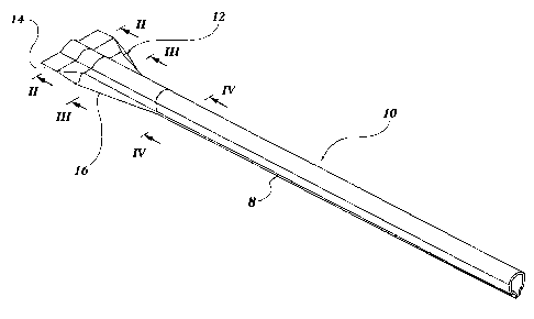
A reinforcing bar for body and/or chassis parts of a motor vehicle includes a
one-piece element (8) extending from one end of the bar to the other and
having a median portion (10) with a closed tubular cross section and at least
one end portion (12) comprising an open-section distal portion (14) and a
proximal portion (16) which connects the said distal portion (14) to the
median portion (10).


French Abstract

La présente invention concerne une barre de renfort destinée à des parties de carrosserie et/ou de châssis d'un véhicule automobile, ladite barre comprenant un élément monobloc (8) s'étendant d'une extrémité de la barre à l'autre, et présentant une partie médiane (10) ayant une section transversale tubulaire fermée, et au moins une partie terminale (12) comprenant une partie distale à section ouverte (14) et une partie proximale (16) qui relie ladite partie distale (14) à la partie médiane (10).

Claims

Note: Claims are shown in the official language in which they were submitted.

8
CLAIMS
1. A reinforcing bar for body and/or chassis parts of a motor
vehicle, comprising:
a one-piece element (8) extending from one end of the bar to
the other and having a median portion (10) with a closed tubular
section and at least one end portion (12) which includes an open-
section distal portion (14) and a proximal portion (16) which
connects the distal portion (14) to the median portion (10);
at least one stiffening element (28, 28a-c) for stiffening
the one-piece element, wherein the at least one stiffening
element (28, 28a-c) is arranged externally of the median portion
(10) of the one-piece element (8); and
wherein the closed tubular section of the median portion
(10) is obtained by folding a steel sheet, the edges (24) of
which are enclosed by the stiffening element (28a-c).
2. A bar according to Claim 1, characterised in that each of
the end portions (12) includes an open-section distal portion
(14), the extent of which, transverse the longitudinal axis of
the bar, is greater than that of the cross section of the median
portion (10), and a proximal portion (16) connecting the said
distal portion (14) to the median portion (10).
3. A bar according to Claim 1 or Claim 2, characterised in that
the cross section of the said proximal portion (16) varies
gradually from the open section of the distal portion (14) to the
closed section of the median portion (10).

9
4. A bar according to any one of Claims 1 to 3, characterised
in that the extent of the said distal portion (14) transverse the
longitudinal axis of the bar is greater than that of the cross
section of the median portion (10).
5. A bar according to any one of Claims 1 to 4, characterised
in that the closed tubular section of the median portion (10) is
obtained by folding a sheet of steel until the terminal side
edges (26) are adjacent.
6. A bar according to Claim 5, characterised in that the
adjacent edges (26) are welded together, by spot welding or with
a continuous seam.
7. A bar according to any one of Claims 1 to 6, characterised in
that it includes a plurality of stiffening elements (28, 28a-c).
8. A bar according to any one of Claims 1 to 7, characterised
in that the said at least one stiffening element (28, 28a-c) is
fixed to the element (8).
9. A bar according to Claim 8, characterised in that the
stiffening element (28, 28a-c) is fixed to the one-piece element
(8) by means of welding.
10. A bar according to any one of Claims 1 to 9, characterised
in that the said at least one stiffening element (28, 28a-c)
closes the cross section of the median portion (10).

10
11. A bar according to any one of Claims 1 to 10, characterised
in that the said at least one stiffening element (28) is an
insert inside the median portion (10) having a closed tubular
section.
12. A bar according to Claim 11, characterised in that the
closed tubular section of the median portion (10) is achieved by
folding a steel sheet around the stiffening element (28).

Description

Note: Descriptions are shown in the official language in which they were submitted.


CA 02414540 2002-12-23
WO 01/92042 PCT/IB00/01772
Reinforcing rod for body and/or chassis element of a motor
vehicle
The present invention relates to a reinforcing bar for a body
and/or chassis part of a motor vehicle, for example an anti-
intrusion bar for a door, an energy-absorbing cross member or
the like.
More particularly, such a bar includes a median. portion, for
providing the required mechanical strength, and end portions
fox fitting it to adjacent body and/or chassis parts of the
motor vehicle.
The object of the present invention is to provide a reinforcing
bar which is simple to produce but able to ensure the aforesaid
properties of mechanical strength and connectability to other
components of the motor vehicle.
This object is achieved by providing a reinforcing bar which
includes a one-piece structure extending from one end of the
bar to the other and having a median portion with a closed
tubular cross section and at least one end portion comprising a
distal portion with an open section and a proximal portion
connecting the said distal portion to the median portion.
In the description which follows, the expression "closed
tubular cross section" should be understood to include both'
structures which are effectively closed and tubular structures
which. are open along a generatrix, with the edges simply
adjacent or possibly joined at longitudinally spaced points.

CA 02414540 2002-12-23
WO 01/92042 PCT/IB00/01772
2
In addition, this expression also refers to structures which
are closed owing to the presence of one or more additional
elements, which increase the rigidity of the aforesaid one-
piece element.
Further characteristics and advantages of the present invention
will become apparent from the detailed description which
follows, provided purely by way of non-limitative example, with
reference to the appended drawings, in. which:
Figure 1 is a perspective view of a bar of the invention,
Figures 2 to 4 are sections taken on the lines II-II, III-
III and IV-IV respectively of Figure l,
Figure 5 is a perspective view of a variant of a bar of
the .invention, with an internal element for increased rigidity,
Figure 6 is a section taken on the line VI-VT of Figure 5,
Figure 7 is a view corresponding to that of Figure 6 but
illustrating a variant of an internal element for increased
rigidity, and
Figures 8 to 10 are views corresponding to that of Figure
4 illustrating respective variants of a bar of the invention,
each with an external stiffening element.
A reinforcing bar for body and/or chassis parts of a motor
vehicle includes (Figures 1-4) a one-piece structure 8~
extending from one end of the bar to the other and including a
median portion 10 and end portions 1.2. For the sake of
simplicity, Figure ~. shows only one of these end portions 12,
the characteristics thereof being equivalent to those of the
end not shown.

CA 02414540 2002-12-23
WO 01/92042 PCT/IB00/01772
3
The median portion 10 has a closed tubular cross section, while
each end portion 12 includes a distal portion 14 with an open
cross section and an extent transverse the longitudinal axis of
the bar greater than that of the cross section of the median
portion 10, and a proximal portion 1&, joining the distal
portion 14 to the median portion 10.
Lengthwise, this latter is rectilinear but, in alternative
embodiments of the invention, not illustrated, it could be
curved in one or more dimensions.
The crass section (Figure 2) of the distal portion 14 is
substantially flat with a central projection 18 in the~shape of
a segment of a circle, - thereby making the bar easy to fit, by
welding for example, to adjacent parts of the body and/or
chassis. In alternative embodiments of the invention, not
illustrated, the extent of the distal portion 14 transverse the
longitudinal axis of the bar could be equal to or less than
that of the cross section of the median portion 10.
The cross section (see Figure 3) of the proximal portion 16 of
the element 8 preferably varies gradually from the open section
of the distal portion 14 to the closed section of the median
portion 10.
This latter (see Figure 4) has two converging straight sides 20
j oined at the top by a curved portion 22 and at the bottom by
two ends 24 with facing surfaces 26 thereby ensuring that the
bar has the required mechanical strength.

CA 02414540 2002-12-23
WO 01/92042 PCT/IB00/01772
4
In other embodiments of the invention not illustrated, the
various portions of the bar could differ from those described,
adapting thereby to specific functional requirements while
still providing the necessary properties of simple fitting and
mechanical strength. For example, the .closed tubular section
of the median portion 10 could, in principle, be of any shape
instead of that illustrated, that is circular, square,
polygonal arid the like. In addition, the shape and/or the
orientation in space of the closed tubular section could vary
along the length of the median portion 10, in principle even.
from one point to another. It is thus possible to give the bar
optimal geometric characteristics, thereby giving it
advantageous properties in terms of the precise variability of
the moment of inertia, mechanical strength, weight reduction
and the like, with a view to specific functional requirements.
The bar as described can be manufactured from a flat steel
sheet, for example, and then formed, in accordance with the
above description, along various portions of its length. In
particular, the sheet could be folded into a closed tubular
structure at the median portion 10 with the facing edges 26
being welded together, either by spots or by a continuous
longitudinal seam.
The material used for the bar is not critical in the context of
the invention and could, in principle, be any material, that is
a metal, a plastics material or a composite, provided it can be
formed into the required shape.

CA 02414540 2002-12-23
WO 01/92042 PCT/IB00/01772
Figures 5 and 6, in which the same numbers used in Figures 1 to
4 refer to identical or equivalent parts, illustrate a variant
of the bar of the invention .
In this case, a stiffening element 28, with a cruciform
section, is inserted into the median portion 10 of the element
8, with the lower arm 30 of the cross fixed, for example by
welding, to the facing edges 26 of the median portion of the
element 8, between which it is inserted. The arm 30 thus closes
the cross section of the median portion 10. The distal ends of
the remaining arms 32 of the cruciform member brace respective
portions of the internal surface of the portion 10 with which
they are in contact.
The element 28 thus reinforces the structure of the element 8,
providing the bar with the required mechanical strength.
The length and position of the element 28 can vary in
dependence on the requirements to be met. It can extend for the
entire length of the median portion or for a fraction thereof,
in any position. Alternatively, there could be several separate
elements 28, provided to strengthen specific portions of the
element 8. As an alternative, or in addition to the above, one
or more elements 28 could be arranged at the site of at least
one of the end portions 12.
The cross section of the element or elements 28 can vary from
that shown in Figure 6 substantially without limitation, other
than those imposed by the need to make the bar sufficiently
rigid.

CA 02414540 2002-12-23
WO 01/92042 PCT/IB00/01772
6w
To this end, Figure 7 shows a further example of cross section
for a stiffera:ing element 28, that is a hollow triangle with an
appendage 34 welded to the facing edges 26 of the median
portion 1.0 of the element 8 between which it is inserted.
Figures 8 to 10, in which the reference numerals used in
earlier drawings indicate identical or equivalent parts,
illustrate additional embodiments of the invention provided
with a stiffening element arranged externally of the median
portion 10 of the element 8.
In the bar of Figure 8, the stiffening element 28a has a U-
shape section and encloses the adjacent ends 24.
In the bar of Figure 9, the stiffening element 28b has a
horizontal C-shape section enclosing the horizontally spread
ends 24.
Tn the bar of Figure 10, the stiffening element 28c has a W-
shape section enclosing the partially spread ends 24.
The stiffening elements 28a-c can be used instead of or in
addition to the stiffening elements 28 arranged inside the
median portion 10 of the element 8.
The length and position of the elements 28a-c may be varied in
dependence on the requirements to be satisfied. They may thus
extend the entire length of the median portion, or for a
fraction thereof arid in any position. Alternatively, there

CA 02414540 2002-12-23
WO 01/92042 PCT/IB00/01772
7
could be several separate elements 28a-c, provided to stiffen
specific portions of the element 8.
The elements 28a-c can be fitted to the element 8 by means of
any known method, for example by welding, clinching, punching
or any combination thereof. The cross section of the elements
28a-c could of course also vary with respect to those
illustrated in Figures 8-10 substantially without limit, except
for those imposed by the need to give the bar the required
stiffness.
Naturally, the principle of the invention remaining the same,
manufacturing details and embodiments may vary widely from
those described purely by way of example, without departing
thereby from the scope of the invention. In particular, in
dependence on particular conditions of use, the bar could
include a one-piece structure with a single end portion
including a distal portion with an open cross section and a
proximal portion connecting the distal portion to the median
portion, having a section like those described above.

Representative Drawing
A single figure which represents the drawing illustrating the invention.
Administrative Status

2024-08-01:As part of the Next Generation Patents (NGP) transition, the Canadian Patents Database (CPD) now contains a more detailed Event History, which replicates the Event Log of our new back-office solution.

Please note that "Inactive:" events refers to events no longer in use in our new back-office solution.

For a clearer understanding of the status of the application/patent presented on this page, the site Disclaimer , as well as the definitions for Patent , Event History , Maintenance Fee  and Payment History  should be consulted.

Event History

Description Date
Time Limit for Reversal Expired 2010-11-30
Letter Sent 2009-11-30
Grant by Issuance 2008-09-09
Inactive: Cover page published 2008-09-08
Inactive: Final fee received 2008-06-25
Pre-grant 2008-06-25
Notice of Allowance is Issued 2008-02-04
Letter Sent 2008-02-04
Notice of Allowance is Issued 2008-02-04
Inactive: Approved for allowance (AFA) 2007-11-16
Amendment Received - Voluntary Amendment 2007-10-11
Inactive: S.30(2) Rules - Examiner requisition 2007-06-08
Letter Sent 2005-11-16
Request for Examination Requirements Determined Compliant 2005-11-07
All Requirements for Examination Determined Compliant 2005-11-07
Request for Examination Received 2005-11-07
Inactive: Office letter 2004-08-17
Inactive: Multiple transfers 2004-07-22
Inactive: Cover page published 2003-03-04
Inactive: Applicant deleted 2003-02-28
Inactive: Notice - National entry - No RFE 2003-02-28
Application Received - PCT 2003-02-03
National Entry Requirements Determined Compliant 2002-12-23
Application Published (Open to Public Inspection) 2001-12-06

Abandonment History

There is no abandonment history.

Maintenance Fee

The last payment was received on 2007-09-28

Note : If the full payment has not been received on or before the date indicated, a further fee may be required which may be one of the following

  • the reinstatement fee;
  • the late payment fee; or
  • additional fee to reverse deemed expiry.

Please refer to the CIPO Patent Fees web page to see all current fee amounts.

Owners on Record

Note: Records showing the ownership history in alphabetical order.

Current Owners on Record
E.M.A.R.C. S.P.A.-ENGINEERING MACCHINE ATTREZZATURE RAPPRESENTANZE CONSULENZE
Past Owners on Record
PIETRO PASSONE
Past Owners that do not appear in the "Owners on Record" listing will appear in other documentation within the application.
Documents

To view selected files, please enter reCAPTCHA code :


To view images, click a link in the Document Description column. To download the documents, select one or more checkboxes in the first column and then click the "Download Selected in PDF format (Zip Archive)" or the "Download Selected as Single PDF" button.

List of published and non-published patent-specific documents on the CPD .

If you have any difficulty accessing content, you can call the Client Service Centre at 1-866-997-1936 or send them an e-mail at CIPO Client Service Centre.


Document
Description 
Date
(yyyy-mm-dd) 
Number of pages   Size of Image (KB) 
Abstract 2002-12-23 1 49
Drawings 2002-12-23 5 65
Description 2002-12-23 7 285
Claims 2002-12-23 3 89
Representative drawing 2003-03-04 1 8
Cover Page 2003-03-04 1 36
Claims 2007-10-11 3 72
Cover Page 2008-08-26 1 38
Notice of National Entry 2003-02-28 1 200
Reminder - Request for Examination 2005-08-02 1 115
Acknowledgement of Request for Examination 2005-11-16 1 176
Commissioner's Notice - Application Found Allowable 2008-02-04 1 164
Maintenance Fee Notice 2010-01-11 1 170
PCT 2002-12-23 7 223
Fees 2003-10-17 1 24
Correspondence 2004-08-17 1 15
Correspondence 2008-06-25 1 32