Language selection

Search

Patent 2414575 Summary

Third-party information liability

Some of the information on this Web page has been provided by external sources. The Government of Canada is not responsible for the accuracy, reliability or currency of the information supplied by external sources. Users wishing to rely upon this information should consult directly with the source of the information. Content provided by external sources is not subject to official languages, privacy and accessibility requirements.

Claims and Abstract availability

Any discrepancies in the text and image of the Claims and Abstract are due to differing posting times. Text of the Claims and Abstract are posted:

  • At the time the application is open to public inspection;
  • At the time of issue of the patent (grant).
(12) Patent Application: (11) CA 2414575
(54) English Title: ELONGATED PNEUMATICAL TOOL WITH REPLACEABLE SOFT GRIP
(54) French Title: OUTIL PNEUMATIQUE ALLONGE A POIGNEE MOLLE INTERCHANGEABLE
Status: Deemed Abandoned and Beyond the Period of Reinstatement - Pending Response to Notice of Disregarded Communication
Bibliographic Data
(51) International Patent Classification (IPC):
  • B25F 05/00 (2006.01)
  • B25F 05/02 (2006.01)
(72) Inventors :
  • NOWAK, DENNIS A., JR. (United States of America)
  • BEER, JOSHUA M. (United States of America)
  • BREHM, JAMES R. (United States of America)
(73) Owners :
  • SNAP-ON TECHNOLOGIES, INC.
(71) Applicants :
  • SNAP-ON TECHNOLOGIES, INC. (United States of America)
(74) Agent: SMART & BIGGAR LP
(74) Associate agent:
(45) Issued:
(86) PCT Filing Date: 2002-03-25
(87) Open to Public Inspection: 2002-10-10
Availability of licence: N/A
Dedicated to the Public: N/A
(25) Language of filing: English

Patent Cooperation Treaty (PCT): Yes
(86) PCT Filing Number: PCT/US2002/009216
(87) International Publication Number: US2002009216
(85) National Entry: 2002-12-30

(30) Application Priority Data:
Application No. Country/Territory Date
09/821,147 (United States of America) 2001-03-29

Abstracts

English Abstract


A housing (11) for a pneumatic tool (10) includes a head portion (14), a
middle portion (13), and a handle portion (12). A sleeve (17) is disposed over
the middle portion of a pneumatic tool with a rear portion of the sleeve
spaced from the outer surface (11a) of the housing. A grip (27) made of pliant
material, preferably rubber or a synthetic rubber compound encloses the handle
portion. The grip includes a front lip (28), and a rear flange (29). Once
fully inserted on the handle, the sleeve and the external surface of the
housing cooperate to retain the front lip therebetween, preventing the front
lip from peeling off the handle portion. An adaptor (35) engages an air inlet
(19) at a distal end (23) of the handle portion. The adaptor can include a
washer (38) engageable with the air inlet for limiting the depth of insertion
of the adaptor in the air inlet and for inhibiting rearward movement of the
grip (27).


French Abstract

Un logement (11) pour un outil pneumatique (10) comporte une partie tête (14), une partie médiane (13) et une partie manche (12). Une gaine (17) est prévue sur la partie médiane de l'outil pneumatique, une partie arrière de la gaine étant espacée de la surface extérieure (11a) du logement. Une poignée (27) en matériau flexible, de préférence en caoutchouc ou en composé caoutchouteux synthétique, entoure la partie manche. Ladite poignée comporte une lèvre avant (28), un rebord arrière (29). Une fois que la gaine est insérée intégralement sur le manche, celle-ci et la surface extérieure du logement coopèrent pour retenir la lèvre avant entre eux deux, ce qui empêche la lèvre avant de se détacher de la partie manche. Un adaptateur (35) s'adapte dans une entrée d'air (19) située au niveau d'une extrémité distale (23) de la partie manche. L'adaptateur peut comprendre une rondelle d'étanchéité (38) s'adaptant dans l'entrée d'air, pour limiter la profondeur d'insertion de l'adaptateur dans l'entrée d'air et pour empêcher le déplacement vers l'arrière de la poignée (27).

Claims

Note: Claims are shown in the official language in which they were submitted.


8
What Is Claimed Is:
A pneumatic tool comprising:
an elongated housing having a middle portion and a handle portion extending
longitudinally therefrom, the middle portion having a sleeve disposed thereon,
the handle
portion having an external surface, a proximal end adjacent to the middle
portion and a
distal end which defines an air inlet.
a detachable grip defining an internal cavity sized to accommodate the handle
portion, and having a front lip and a rear flange, the grip being disposed on
the handle with
the sleeve and the external surface in cooperation to retain the front lip
therebetween and
with the rear flange engaging the air inlet; and
an adaptor defining an air passage inserted into the air inlet
2. The pneumatic tool of claim 1, where the adaptor includes a washer and a
bushing, the washer abutting directly against the air inlet when the adaptor
is fully inserted
into the air inlet, the washer cooperating with the distal end of the handle
portion to protect
the rear flange of the grip from peeling
3. The pneumatic tool of claim 1, wherein the grip is formed of a synthetic
rubber material.
4. The pneumatic tool of claim 1, wherein the handle portion has a plurality
of
ribs, and wherein the internal surface of the grip has channels positioned to
respectively
receive the ribs.
5. The pneumatic tool of claim 1, wherein the adaptor includes a filter screen
extending across the air passage.
6. The pneumatic tool of claim 1, and further comprising a push-button
mechanism depending from the handle portion, and wherein an annular wall
extends from

9
the external surface to surround the push-button mechanism, the grip having an
aperture
therethrough sized to engage the annular wall.
7. The pneumatic tool of claim 1, wherein the grip has an external surface
ergonomically shaped to accommodate a user's hand.
8. A pneumatic tool comprising:
a housing having a middle portion and a handle portion extending
longitudinally
therefrom, the handle portion having an external surface, a proximal end
adjacent to the
middle portion, and a distal end which defines an end surface and an air inlet
projecting
therefrom;
a grip having a front lip and a rear flange, the grip disposed on the external
surface
of the handle portion and the rear flange overlying the end surface; and
an adaptor secured to the inlet, the adaptor defining an air passage and
including a
washer and a bushing, the washer abutting directly against the air inlet when
the adaptor is
fully inserted into the air inlet, the air inlet projecting beyond the rear
flange so that the
washer can engage the air inlet without touching the rear flange.
9. The pneumatic tool of claim 8 and further comprising means for preventing
rotation of the grip relative to the handle; the means including complementary
structures
located on the external surface of the handle portion and on the internal
surface of the grip.
10. The pneumatic tool of claim 9, wherein the housing includes a sleeve
disposed on the middle portion and partially extending over the handle
portion, the sleeve
and the external surface cooperating to retain the front lip therebetween.
11. The pneumatic tool of claim 10, wherein the means for preventing rotation
includes a plurality of ribs extending longitudinally along the external
surface of the

10
handle portion and arranged in diametrically opposed pairs, and channels
positioned on the
internal surface of the grip to respectively receive the ribs.
12. The pneumatic tool of claim 11 wherein the grip is formed of a synthetic
rubber material.
13. The pneumatic tool of claim 12 wherein the adaptor assembly includes a
filter screen extending across the air passage.
14. The pneumatic tool of claim 13, and further comprising a push-button
mechanism depending from the handle portion, an annular wall extending from
the
external surface of the handle portion surrounding the push-button mechanism,
and
wherein the grip includes an aperture sized and positioned to engage the
annular wall to
inhibit axial and circumferential movement of the grip.
15. A method for retaining a soft grip on an elongated pneumatic tool having a
middle portion and a handle portion, the handle portion defining an air inlet
and having an
external surface, the method comprising:
providing a sleeve sized to accommodate the middle portion and extend over the
handle portion;
providing a replaceable grip with a front lip and a rear flange, the grip
sized to
accommodate the handle; and
disposing the soft grip on the external surface of the handle portion so that
the front
lip is disposed between the sleeve and the external surface.
16. The method of claim 15, and further comprising the steps of providing an
adaptor sized to engage the air inlet and having a washer portion extending
radially
therefrom and mounting the adaptor on the handle portion so that it does not
engage the
grip.

11
17. The method of claim 16 and further comprising positioning the adaptor to
protect the, rear flange of the grip from peeling.
18. The method of claim 17 and further comprising providing interengaging
structures on the grip and the handle portion to prevent relative rotational
movement
thereof.

Description

Note: Descriptions are shown in the official language in which they were submitted.


CA 02414575 2002-12-30
WO 02/078912 PCT/US02/09216
ELONGATED PNEUMATIC TOOL WITH REPLACEABLE SOFT GRIP
Back round
This application relates generally to a pneumatic tool. More particularly,
this
application relates to an elongated pneumatic tool with a replaceable soft
grip.
Elongated pneumatic hand tools such as air ratchets are well known. These
devices typically include a head portion, a middle portion, and a handle
portion, all of
which may be disposed in longitudinal alignment. The head portion contains the
drive end
1 o which couples to an attachment or a fastener to perform work. The middle
portion
contains a pneumatic motor which drives the rotary movement of the drive end.
The
handle portion provides an external surface fox the user to grasp, and also
includes an
airway for,the flow of compressed air into the pneumatic motor.
In order to operate an elongated pneumatic tool, the user must maintain a
solid
15 grip on the handle portion with one hand, while controlling the flow of
compressed air into
the tool with that same hand. This task is made more difficult because
rotational. torque
generated during the use of the elongated pneumatic tool can cause the tool to
slip from
the grasp of the user. Vibrational forces generated during the normal
operation may also
cause the hand to lose its grip or may tire the hand, prematurely weakening
the user's grip.
a o Consequently, it is important that the handle portion provide good
traction with the hand
and also provide some damping of vibrational forces.
A grip may be disposed on the handle to provide better traction and/or thermal
protection of the hand. The grip is usually made of a rigid plastic material
because rigid
plastic is generally more durable, and can be secured onto the handle in a
conventional
~ s manner by using fasteners. However, these rigid grips provide little
protection against

CA 02414575 2002-12-30
WO 02/078912 PCT/US02/09216
2
vibrational forces, and they still provide less traction than grips made of
more pliant
materials, such as rubber.
Softer grips made of pliant materials dampen vibrations and readily conform to
the
user's hand for better traction, but they are typically not utilized because
of the difficulty in
retaining these grips on the handle portion. Pliant materials, such as rubber,
typically
degrade and fail when fastened onto a surface with a fastener. The pressure
exerted on the
material by the fastener typically wears down the area surrounding the
fastener
prematurely. Pliant materials can be glued onto the handle, but this is a
permanent bond
and makes replacing worn grips quite difficult. Pliant grips can also be
inserted onto the
z o handle without being fastened thereto, but dirt and debris tend to worlc
themselves between
the grip and the housing, reducing traction between the two and causing the
grip to slide.
Consequently, while there is a need for a pneumatic tool which has a grip
portion that is
made of a pliant material, this need has been Ieft largely unsatisfied due to
the difficulty of
retaining a pliant grip on a handle.
15 . Summary
Therefore, this application to provides a pneumatic powered tool that avoids
the
disadvantages of prior designs while affording additional structural and
operating
advantages.
An important feature is the provision of a pneumatic tool with a pliant hand
grip
~ o that is capable of absorbing a substantial amount of the vibrational
forces that are
generated during the normal operation of the tool.
Another important feature is the provision of a pneumatic tool with a pliant
hand
grip which provides greater traction between a user's hand and the tool.
Another important feature is the provision of a pneumatic tool with a pliant
hand

CA 02414575 2002-12-30
WO 02/078912 PCT/US02/09216
3
grip that is easily replaceable when worn down.
Another important feature is the provision of a pneumatic tool with a pliant
hand
grip that engages the external surface of the handle portion so as to prevent
relative
movement of the grip relative thereto.
Another important feature is the provision of a pneumatic tool with a hand
grip that
prevents the infiltration of materials between the grip and the handle.
Another important feature is the provision of a method of mounting a pliant
hand
grip on an elongated pneumatic tool.
Brief Description of the Drawings
1 o For purposes of facilitating and understanding the subject matter sought
to be
protected, there is illustrated in the accompanying drawings ari embodiment
thereof, from
an inspection of which, when considered in connection with the following
description, the
subject matter sought to be protected, its construction and operation, and
many of its
advantages should be readily understood and appropriated.
15 FIG. 1 is an exploded perspective of an embodiment of the pneumatic power
tool
and grip therefor.
FIG. 2 is an enlarged sectional view of the handle portion of the pneumatic
tool of
FIG. 1. °
FIG. 3 is a side elevational view of the hand grip of the tool of FIG. 2.
z o FIG. 4 is a further enlarged view of Area 4 in FIG. 2.
FIG. 5 is a further enlarged cross sectional view of the handle portion of
FIG. 2
taken along lines 5-5.
FIG. 6 is a further enlarged view of Area 6 in FIG. 2.
Detailed Description

CA 02414575 2002-12-30
WO 02/078912 PCT/US02/09216
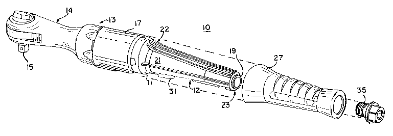
Referring to FIG. 1, an embodiment of an elongated pneumatic tool 10 in
accordance with the principles of this application is shown. This embodiment
of the
pneumatic tool 10 is configured as an air ratchet for the purpose of
illustration only. A
pneumatic tool in accordance with the principles of this application can be
otherwise
s configured to perform other functions. The pneumatic tool 10 includes an
elongated
housing 1 I which encloses a majority of the pneumatic tool 10. The housing l
lincludes a
handle portion 12, a cylindrical middle portion 13, and a head portion 14, all
relatively
linearly aligned.
The head portion 14 encloses a drive shaft (not shown) which is coupled
through
1 o suitable gearing to a drive square 15 and to a pneumatic motor 16 (FIG.
2). A plurality of
different attachments can engage the drive square 15, enabling the pneumatic
tool 10 to
perform a variety of tasks.
Referring also to FIGS. 2 and 4, the middle portion 13 houses the pneumatic
motor
16 therein. A vent (not shown) can extend through the middle portion 13 to
provide a
x5 pathway for exhaust to escape from the housing. A sleeve I7 can be disposed
over the
middle portion 13 to guide the flow of exhaust as it leaves the vent.
Preferably, a rear
portion of the sleeve 17 is spaced from the outer surface 1 la of the housing
1 I, as at 17a
(FIG. 4).
The handle portion 12 extends from the middle poition 13 defining an airway 18
2 o therein and an air inlet 19 in communication with the airway 18. The
handle portion 12
can include an elongated and generally frustoconical external surface 21, a
proximal end
22 adjacent to the middle portion 13, and a distal end suxface 23 from which
the air inlet
19 projects (FIG. 6). A grip 27 is disposed on the eternal surface 21.
Referxing to FIGS. 1 and 5, a rib 24 may extend longitudinally on the external

CA 02414575 2002-12-30
WO 02/078912 PCT/US02/09216
surface of the handle portion to prevent rotational movement of the grip
relative to the
handle portion 12. Preferably, a plurality of ribs 24 is utilized, with ribs
spaced apart
circumferentially to provide more uniform resistance to rotation.
Referring to FIGS. 2 and 5, a push-button mechanism 25 depends from the handle
portion 12 and is coupled to a valve assembly 26 that controls flow of
compressed air to
the pneumatic motor. Depression of the push-button mechanism 25 opens the
valve
assembly 26 allowing compressed air to flow to the pneumatic motor. An wall 31
may
extend from the external surface 21 surrounding the push-button mechanism 25
to inhibit
axial and circumferential movement of the grip 27.
1o Referring to FIGS. 2, 3 and 5, the grip 27 is made of a pliant material,
preferably
rubber or a synthetic rubber compound. The grip defines an internal cavity 32
sized to
enclose the handle portion 12 therein and has a front lip 28, defining a
proximal end
opening 39, and a rear flange 29 which wraps over the distal end surface 23 of
the handle
portion l2~and defines a distal end opening 40. The grip is preferably
ergonomically
shaped to accommodate a user's hand.
The interior cavity 32 of the grip 27 has an internal surface 30 which may
include
channels 33 extending longitudinally thereon. The channels 33 are arranged
complementary to the ribs 24 on the handle portion 12, and are dimensioned to
respectively receive the rib 24. An aperture 41 can extend through the grip 27
to receive
a o the wall 31.
Referring to FTGS. 2 and 6, an adaptor 35 engages the air inlet 19 of the
handle
portion 12. The adaptor can include a bushing 36 which defines a passageway 34
therein.
A filter screen 37 can extend across the passageway to filter debris carried
by the
compressed air. The adaptor 35 can include a washer 38 engageable with the air
inlet 19

CA 02414575 2002-12-30
WO 02/078912 PCT/US02/09216
for limiting the depth of insertion of the adaptor 35 in the air inlet 19.
Referring to FIGS. 4, 5, and 6, the grip 27 is secured onto the handle by
first
aligning the channels 33 with the ribs 24, and inserting the handle portion 12
into the
proximal end opening 39 of the grip 27. Once fully inserted, the sleeve 17 and
the external
surface of the housing 11 at 11 a (FIG. 4) cooperate to retain the front lip
28 therebetween,
preventing the front lip 28 from peeling off the handle portion 12. Each rib
24 should be
disposed within a channel 33, thereby preventing rotation of the grip relative
to the handle
portion. The rear flange 29 engages the distal end surface 23 of the handle
portion 12.
The adaptor 35 is inserted into the air inlet i 9 and is preferably threadedly
secured
1 o to the airway 18. The washer 3 8 abuts the air inlet 19 and prevents
further axial
movement within the airway 18. The washer 3 8 has outer diameter greater than
the
diameter of the distal end opening 40 defined by the rear flange 29 to protect
the rear
flange 29 from catching on objects which might cause it to peel back from the
handle, and
to inhibit rearward movement of the grip 27. The air inlet 19 projects
rearwardly from the
' distal end surface 23 a distance greater than the thickness of the rear
flange 29 so that the
washer 38 doesn't touch the flange 29 during installation of the adaptor 35.
Thus, the
washer 38'does not apply direct pressure on the rear flange 29, which might
cause twisting
of the rear flange during tightening of the bushing 36.
The use of pliant materials, such as rubber, to form a grip which covers a
handle of
a o an elongated pneumatic tool has several advantages. Pliant grips provide
increased
damping of vibrations which propagates through a pneumatic tool during normal
operation, reducing discomfort to the user's hands. Furthermore, a pliant grip
yields to the
contours of a user's hand, enabling the grip to provide for greater comfort
during use and
increasing the traction between the user's hand and the tool.

CA 02414575 2002-12-30
WO 02/078912 PCT/US02/09216
The matter set forth in the foregoing description and accompanying drawings is
offered by way of illustration only and not as a limitation. While a
particular embodiment
has been shown and described, it will be obvious to those skilled in the art
that changes
and modifications may be made without departing from the broader aspects of
applicants'
contribution. The actual scope of the protection sought is intended to be
defined in the
following claims when viewed in their proper perspective based on the prior
art.

Representative Drawing
A single figure which represents the drawing illustrating the invention.
Administrative Status

2024-08-01:As part of the Next Generation Patents (NGP) transition, the Canadian Patents Database (CPD) now contains a more detailed Event History, which replicates the Event Log of our new back-office solution.

Please note that "Inactive:" events refers to events no longer in use in our new back-office solution.

For a clearer understanding of the status of the application/patent presented on this page, the site Disclaimer , as well as the definitions for Patent , Event History , Maintenance Fee  and Payment History  should be consulted.

Event History

Description Date
Application Not Reinstated by Deadline 2007-03-26
Time Limit for Reversal Expired 2007-03-26
Deemed Abandoned - Failure to Respond to Maintenance Fee Notice 2006-03-27
Inactive: Cover page published 2003-03-06
Letter Sent 2003-03-04
Inactive: Notice - National entry - No RFE 2003-03-04
Application Received - PCT 2003-02-03
National Entry Requirements Determined Compliant 2002-12-30
Application Published (Open to Public Inspection) 2002-10-10

Abandonment History

Abandonment Date Reason Reinstatement Date
2006-03-27

Maintenance Fee

The last payment was received on 2005-03-02

Note : If the full payment has not been received on or before the date indicated, a further fee may be required which may be one of the following

  • the reinstatement fee;
  • the late payment fee; or
  • additional fee to reverse deemed expiry.

Patent fees are adjusted on the 1st of January every year. The amounts above are the current amounts if received by December 31 of the current year.
Please refer to the CIPO Patent Fees web page to see all current fee amounts.

Fee History

Fee Type Anniversary Year Due Date Paid Date
Basic national fee - standard 2002-12-30
Registration of a document 2002-12-30
MF (application, 2nd anniv.) - standard 02 2004-03-25 2004-03-08
MF (application, 3rd anniv.) - standard 03 2005-03-25 2005-03-02
Owners on Record

Note: Records showing the ownership history in alphabetical order.

Current Owners on Record
SNAP-ON TECHNOLOGIES, INC.
Past Owners on Record
DENNIS A., JR. NOWAK
JAMES R. BREHM
JOSHUA M. BEER
Past Owners that do not appear in the "Owners on Record" listing will appear in other documentation within the application.
Documents

To view selected files, please enter reCAPTCHA code :


To view images, click a link in the Document Description column. To download the documents, select one or more checkboxes in the first column and then click the "Download Selected in PDF format (Zip Archive)" or the "Download Selected as Single PDF" button.

List of published and non-published patent-specific documents on the CPD .

If you have any difficulty accessing content, you can call the Client Service Centre at 1-866-997-1936 or send them an e-mail at CIPO Client Service Centre.


Document
Description 
Date
(yyyy-mm-dd) 
Number of pages   Size of Image (KB) 
Description 2002-12-29 7 297
Drawings 2002-12-29 3 72
Abstract 2002-12-29 1 71
Claims 2002-12-29 4 138
Representative drawing 2002-12-29 1 21
Notice of National Entry 2003-03-03 1 200
Courtesy - Certificate of registration (related document(s)) 2003-03-03 1 130
Reminder of maintenance fee due 2003-11-25 1 109
Courtesy - Abandonment Letter (Maintenance Fee) 2006-05-22 1 175
Reminder - Request for Examination 2006-11-27 1 118
PCT 2002-12-29 3 95
PCT 2002-12-29 1 31
PCT 2002-12-30 3 135