Note: Descriptions are shown in the official language in which they were submitted.
CA 02414577 2002-12-27
WO 02/00533 PCT/EPO1/07382
CONVEYOR SYSTEM WITH DIVERTING
TRACK NETWORK
CROSS-REFERENCE TO RELATED APPLICATION
This application is a continuation-in-part of commonly assigned application
serial
no. 091606,610 filed June 29, 2000. .
BACKGROUND OF THE INVENTION
This invention relates generally to conveyor diverting systems, and, more
particularly, to conveyor diverting systems having an endless conveying
surface
composed of multiple surface members, each one or group of adjacent ones
mounted
with a laterally movable shoe capable of diverting articles from the conveyor
by pushing
laterally against the articles as they move down the conveyor. Such lateral
pushing
thereby diverts a package, such as from the main conveyor to an adjacent
branch
conveyor, or other receiving structure.
Conveyor diverting systems using a moving conveying surface consisting of a
plurality of parallel surface members, the conveying surface being propelled,
such as by
being mounted to endless chains, have been known for a number of years. Such
diverting systems utilize a diverter shoe movably mounted on one or more
surface
members for lateral movement with respect to the conveying surface under the
guidance
of a track network. The track network is located generally under the conveying
surface
and guides the diverter shoes via pins descending from the diverter shoes and
engaging
the track network. Diverters in the track network selectively transfer
guidance of each
diverter shoe from a track running in the direction of the movement of the
conveying
surface to a diagonal track, or plurality of diagonal tracks, in order to
cause lateral
movement of the diverter shoes. An example of a diverting gate used to
selectively
transfer guidance of diverter shoes between tracks is disclosed in U. S. Pat.
No.
5,409,095, issued to Hoshi et al., and U.S. Pat. No. 5,039,912, issued to
Cotter. In order
to avoid wasted spacing between variable-length packages, such diverting
systems may
include manual or automatic measuring means at an infeed point to cause the
diverter
gate associated with the selected branch conveyor to divert a selected number
of shoes
corresponding in general to the length of the package. Exemplary of this type
of
CA 02414577 2002-12-27
WO 02/00533 PCT/EPO1/07382
a
conveyor are U.S. Pat. No. 3,3fi1,247, issued to James N. Lauzon et al. and
U.S. Pat.
No. 4,738,347, issued to Brouwer, and commonly assigned with the present
invention.
With increased demands for the number of packages to be conveyed by such
conveying systems, the inter-package spacing distance has become a critical
factor in
the design of conveying systems. Decreasing the spacing between packages on
the
conveyor~allows a greater throughput of packages by the conveyor. Conversely,
providing more space between the packages results in a diminished efficiency
and
throughput.
A specifiic minimum inter package spacing is required in this system as a
result of
the rotation of the diverted package as it is initially diverted. Because of
this rotation,
additional inter-package spacing is required to avoid conflick between the
diverting
package and a closely trailing package. This rotation pushes the trailing
comer of the
package adjacent the branch conveyor back a distance, which can be estimated
using
the width (W) of the package and the acute angle (a) which is formed by the
intersection
of the material flow on the main conveyor and the diverter shoe diagonal guide
track.
Using these two variables and assuming that the package rotates about the
trailing
corner opposite the branch conveyors, it will be observed that:
A = Wsin a
where A is the distance the trailing comer adjacent the branch conveyor is
pushed back
by the package's rotation. it is, therefore, necessary with this system that
packages to be
diverted are not spaced closer together than the distance Wsin a.
By way of example, if a diverting branch is oriented at about 20° with
packages 16
inches in width, an inter package distance of approximately 5,5 inches is
necessary. If
the package is 24 inches long, this results in the need for approximately 23%
mare empty
space on the conveyor. A hypothetical system that could divert packages
without any
significant space between packages could thus produce a 23% increase in
package
throughput without any increase in conveyor speed. The high desirability of
such a
system is thus clear.
Prior methods of diverting packages that addresses the problem of reducing the
~0 required inter-package spacing, is described in commonly assigned U.S. Pat.
No.
5,165',515, issued to Michael L. Nitschke et al., which is commonly assigned
with the
present application. This system increases throughput by not rotating the
diverted
packages. This non-rotation is accomplished by using a plurality of generally
parallel
diverting tracks oriented diagonally with respect to the direction of conveyor
movement,
CA 02414577 2002-12-27
WO 02/00533 PCT/EPO1/07382
instead of a single diverting track. Each track has its own diverting gate
which is actuated
to divert the movement of the diverting shoes from the direction of the
conveyor to the
lateral diverting direction. By simultaneously activating more than a single
diverting gate,
a group of diverting shoes corresponding to the measured package length can be
moved
laterally across the conveyor surface. This group of shoes acts along nearly
the entire
length of the package to be diverted and, therefore, causes no rotation of the
package.
Without rotation of the package, the inter-package spacing requirement is
reduced to a
minimum.
However, this technique is not without difficulties. The deliberate non-
rotation of
the packages means the packages will enter the branch conveyor still aligned
parallel to
the main conveyor, but oriented generally diagonally with respect to the
branch conveyor
(i.e., their lengthwise sides are not parallel to the direction of motion of
the branch
conveyor). This orientation significantly increases the necessary width of the
branch
conveyors, resulting in an increase in cost and a reduction in the spacing on
branch
conveyors.
Still another method of diverting packages which reduces the required inter-
package spacing, is described in commonly assigned U.S. Pat. No. 5,927,465,
issued to
Shearer, Jr. With this system, an automatic controller oversees the operation
of the
diverting gates to determine which diverting gates are to be actuated and for
how long,
depending upon the measured length of the packages on the conveyor. Once the
length
of the package is determined, the controller determines whether a package will
be
diverted using one diverting gate or two (or more) diverting gates. For
certain situations,
such as long packages, a single diverter is activated and as many diverting
shoes are
diverted as necessary to divert the package through the single diverting gate.
Packages
diverted in this manner are rotated, with the trailing corner of the package
moving in an
initial rearward direction.
Other packages are diverted with two or more gates in a manner that the
packages are initially diverted out of line with other packages without
substantially rotating
the packages, in the same manner as in Nitschke et al. '515 Patent. After the
initial
diverting, the package is then rotated prior to discharge to the spur. This
has the
advantage of the Nitschke et al. '515 Patent of not requiring increased gaps
between
packages but eliminates the disadvantage of increased spur size. However, some
of the
packages, such as long packages, are still diverted using conventional
techniques and
increased gaps must be provided at both ends of such packages.
CA 02414577 2002-12-27
WO 02/00533 PCT/EPO1/07382
4
It will thus be observed that there exists a need for a conveyor diverting
system
that can divert packages with little or no inter-package spacing, and ensure
that
packages diverted to the branch conveyor are properly aligned, all while
keeping costs to
a minimum.
SUMMARY OF THE INVENTION
The present invention provides a sortation system which achieves efficiency
gains
through reduction of the inter-package spacing. These efficiency gains are
especially
desirable because they can be achieved without the extra power consumption,
noise,
and wear that results from increasing the conveyor speed.
According to one aspect of the present invention, a diverting assembly for
diverting articles from a conveying surface of a conveyor is provided in a
sortation
system. The diverting assembly includes a plurality of movable pushers, a set
of at least
three diverting tracks, a set of at least three diverters, and a controller.
The plurality of
movable pushers are associated with the conveying surface and are adapted to
be
movable transversely across the conveying surface. The diverting tracks are
configured
to guide selected ones of the movable pushers across the conveying surface.
Each of
the diverters are adapted to selectively divert at least one movable pusher
along one of
the diverting tracks when the diverter is activated into a diverting state.
When an article is
to be diverted from the conveying surface, the controller is adapted to select
a subset of
at least two diverters from the set of at least three diverters and activate
the subset into
the diverting state. The subset of diverters includes a first and a second
diverter which
are separated from each other by at least one intermediate diverter which is
not activated
into the diverting state.
According to another aspect of the present invention, a method for diverting
articles from a conveyor having a conveying surface is provided. The method
includes
providing a plurality of movable pushers which are associated with the
conveying surface
and which are adapted to be movable transversely across the conveying surface.
A set
of at least three diverting tracks and at least three diverters are also
provided. The tracks
are configured to guide selected ones of the movable pushers across the
conveying
surface. The diverters are each adapted to selectively divert at least one
movable
pusher along one of the diverting tracks when the diverter is activated into a
diverting
state. The length of an article to be diverted is also determined, and a
subset of at least
two diverters from the set of at least three diverters is selected based upon
the
CA 02414577 2002-12-27
WO 02/00533 PCT/EPO1/07382
determined length of the article to be diverted. The subset of diverters
includes a first
and a second diverter which are separated from each other by at least one
intermediate
diverter. The first and second diverters are activated into the diverting
state while at least
one intermediate diverter is maintained in a nondiverting state.
5 According to still another aspect of the present invention, a diverting
assembly for
diverting articles from a conveying surface of a conveyor is provided. The
diverting
assembly includes a plurality of movable pushers, a plurality of diverting
tracks, and a
plurality of diverters. The movable pushers are associated with the conveying
surFace
and adapted to be movable transversely across the conveying surface. The
diverting
tracks are configured to guide selected ones of the movable pushers across the
conveying surFace. Each of the diverters are adapted to selectively divert at
least one of
the movable pushers along one of the diverting tracks when the diverter is
activated into
a diverting state. A controller is also provided for selecting at least two
diverters from the
plurality of diverters. The controller first activates a downstream one of the
selected
diverters into the diverting state and subsequently activates an upstream one
of the
selected diverters into the diverting state.
According to still further aspects of the present invention, the selection of
which
diverters to activate may be based upon the length of an article to be
diverted. The
activation of the diverters may occur such that one diverter is activated when
the leading
edge of the article to be diverted is adjacent that diverter, and the other
diverter is
activated when the trailing edge of the article to be diverted is adjacent
that other diverter.
The diverters that are activated may be activated simultaneously,
nonsimultaneously, or
a combination thereof. The diverting tracks may also be shaped such that an
article to be
diverted is initially pushed with a nonrotational force by the movable pushers
and then
subsequently pushed with a rotational force by the movable pushers.
The methods and devices of the present invention provide an efficient method
for
diverting articles onto a branch conveyor or other structure. These and other
objects,
advantages, and features of this invention will become apparent upon review of
the
following specification when read in conjunction with the accompanying
drawings. w
BRIEF DESCRIPTION OF THE DRAWINGS
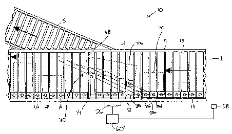
FIG. 1 is a fop plan view of a divert assembly for a conveyor system according
to
one aspect of the invention;
FIG. 2 is a top plan view of the conveyor system of FIG. 1, with a center
portion of
the conveying surface removed to illustrate the underlying structure;
CA 02414577 2002-12-27
WO 02/00533 PCT/EPO1/07382
6
FIG. 3 is the same view as FIG. 2 of an alternative preferred embodiment
thereof;
FIG. 4 is the same view as FIG. 2 of another alternative preferred embodiment
thereof;
FIG. 4a is the same view as FIG. 2 of yet another alternative preferred
S embodiment thereof;
FIG. 5 is the same view as FIG. 2 of still another alternative preferred
embodiment
thereof;
FIG. 6 is a diagram of a single package in various stages of divert, along a
downstream track and an upstream track;
FIG. 7 is a diagram of a single package in various stages of divert, along a
pair of
downstream tracks;
FIG. 8 is a flow chart of a method for diverting a package according to the
invention;.
FIG. 9 is a top plan view of a divert assembly according to still another
aspect of
the present invention; and
FIG. 10 is a flowchart of a method for diverting an article according to the
divert
assembly of FIG. 9.
DESCRIPTION OF THE PREFERRED EMBODIMENTS
Referring spec~cally to the drawings and the illustrative embodiments therein,
a
conveying systerii 10 includes a main conveyor 9 and a plurality of branch
conveyors 5,
of which only one is shown. Although the invention is illustrated for use with
a
unidirectional divert conveyor which diverts articles to one lateral side of
the conveying
surface, it should be understood that its principles may also be used with a
bi-directional
divert conveyor which diverts articles selectively to either lateral side of
the conveyor
surface. Branch conveyor 5 is positioned adjacent to main conveyor 9, and at
an angle,
as is conventional. The arrows illustrate the direction of conveyance for both
main
conveyor 9 and branch conveyor 5.
A conveying surface 1 of main conveyor 9 is defined by a series of surface
members 13 which define a product conveying surface. The lengthwise direction
of
surface members 13 is oriented perpendicular to the direction of movement of
main
conveyor 9. Surface members 13 are supported on either side by side members 2
and
3. The details of the conveying surface are disclosed in U.S. Pat. No.
5,127,510, issued
to Cotter et al., the disclosure of which is hereby incorporated herein by
reference and will
not be repeated.
CA 02414577 2002-12-27
WO 02/00533 PCT/EPO1/07382
7
A series of movable pushers, or diverting shoes, 14 are located along main
conveyor 9, opposite branch conveyor 5 and proximate to side member 2. When
diverting shoes 14 are not being utilized to displace an article off main
conveyor 9 and
onto branch conveyor 5, they travel in sequence along a shoe guideway 8,
adjacent the
longitudinally extending guide track 12. Guide track 12 prevents diverting
shoes 14 from
moving transversely across main conveyor 9 except at the point along main
conveyor 9
at which diverters 25a through 25i are located, or along similar points where
a branch
conveyor connects to main conveyor 9. Diverters 25a through 25i can be seen
attached
along side member 2 of main conveyor 9, and in the path of diverting shoes 14.
Diverters 25a through 25i may be of the type disclosed in commonly assigned
U.S. Pat.
No. 5,038,912, issued to Cotter or of the type disclosed in U.S. Pat. No.
5,409,095,
issued to Hoshi et al., or of the type disclosed in commonly assigned patent
application
serial no. , filed April 23, 2001 by Veit et al for a sortation system
diverter switch ( attorney docket RAP04 P-615A) the disclosures of which are
hereby
incorporated herein by reference.
With reference to FIG. 2, a section of conveying surface 1 has been removed
from the central portion of main conveyor 9 to illustrate the structure of a
diverting track
network 30. Diverting track network 30 includes a plurality of first, or
upstream diverting
tracks 40, and one or more second, or downstream, diverting tracks 50.
Although there
are seven upstream diverting tracks 40 and two downstream diverting tracks 50
illustrated in FIG. 2, it is within the spirit and scope of the invention to
have any number of
upstream diverting tracks 40 and downstream diverting tracks 50. In general,
diverting
tracks 40, 50 span the maximum article length to be transported by conveyor
system 10,
as will be discussed in detail hereinbelow. Downstream diverting tracks 50
traverse
substantially the entire conveying surface 1 at a preselected angle to the
direction of
movement of main conveyor 9. Each downstream diverting track 50 may be
generally
straight or linear throughout its length. Each upstream diverting track 40
terminates
partway across conveying surface 1, at a location that generally relates to
the width of the
package stream conveyed by conveyor 10. In the illustrated embodiment, each
diverting
track 40 includes a linear, or first section 42 which is generally parallel to
downstream
diverting tracks 50, and a second section 44 projecting from the end of first
section 42,
and extending downstream at an obtuse angle to first section 42. Each second
section
44 of upstream diverting tracks 40 is operably coupled to the second section
44 of the
adjacent upstream diverting track 40. Second section 44 of the upstream
diverting track
CA 02414577 2002-12-27
WO 02/00533 PCT/EPO1/07382
40 adjacent to, and immediately upstream of, first downstream diverting track
50a is
operably connected to downstream diverting track 50a, a preselected distance
below end
5.4. Upstream diverting tracks 40 may be integrally formed with second section
44 bent to
achieve the preselected angle. Alternatively, second section 44 may be a
separate
member, operably coupled to first section 42 by any means commonly employed in
the
art. Collectively, second sections 44 form an upwardly curved path, toward
side member
3, as they approach downstream diverting track 50a.
Downwardly depending portions of diverting shoes 14 are diverted to specific
upstream diverting tracks 40a through 40g, and downstream diverting tracks 50a
and
50b by a dedicated diverter 25a through 25i. Diverters 25a through 25i are
electrically
actuated, for example, by shoe divert solenoids, in electrical connection with
a divert
control module 26 as disclosed in Cotter '192 or by magnetic attraction of a
portion of the
diverting shoe as disclosed in Hoshi et al. '095. It will be recognized by
those with
ordinary skill in the art that diverters 25a through 25i may be controlled by
any means
commonly recognized in the art without departing from the spirit and scope of
the
invention.
The number of upstream diverting tracks 40 utilized in conveyor system 10 is
dictated by the maximum length of a package to be handled by the conveyor
system.
Preferably, the distance between downstream diverting track 50b and upstream
diverting
track 40a farthest upstream is approximately equal to, or greater than, the
maximum
length of packages to be diverted along conveyor system 10. The longitudinal
spacing
between upstream diverting tracks 40 and downstream diverting tracks 50 may be
substantially equal to the longitudinal distance of a single surface member
13, so that
each diverting shoe 14 positioned over upstream diverting tracks 40 and
downstream
diverting tracks 50 may be selectively actuated by the associated diverter 25a
through
25i. Alternatively, the longitudinal spacing between upstream diverting tracks
40 and
downstream diverting tracks 50 may be some multiple, such as twice the width
of a
surface member 13, such that every other diverting shoe 14 may be selectively
actuated
when positioned over diverting tracks 40, 50 without departing from the scope
of the
invention.
Conveyor system 10 is equipped with at least one sensor 58, operably connected
to a control system 60, to thereby determine the length of each package being
transported along conveyor system 10. Sensor 58 may be any sensor commonly
used in
the art, and is positioned in proximity to, or along main conveyor 9, upstream
of diverting
CA 02414577 2002-12-27
WO 02/00533 PCT/EPO1/07382
9
track network 30 or upstream of main conveyor 9. Control system 60 is in
electrical
communication with divert control module 26.
When a particular package 70 is to be diverted onto branch conveyor 5, a
signal
is sent from control system 60 to divert control module 26 to thereby cause
the selective
actuation of diverter 25a, and at least one of diverters 25b through 25i to
thereby divert at
least two diverting shoes 14. One diverting shoe will be diverted along a
downstream
diverting track, preferably track 50b, and one along another track thereof,
such as the
other downstream diverting track 50a, or an upstream diverting track 40.
Specifically, the
divert control module 26 will effect actuation of diverter 25a farthest
downstream along
main conveyor 9, which corresponds to downstream diverting track 50b, and the
leading
end 68 of package 70 to be diverted. Simultaneously, control divert module 26
will
actuate a diverter 25b through 25i along a downstream diverting track 50a or
along a
particular upstream diverting track 40, whichever is most proximate to the
trailing end 69
of package 70.
Consequently, diverting shoes 14 will be diverted along downstream diverting
track 50b, and along downstream diverting track 50a, or a particular upstream
diverting
track 40. This will effect non-rotational movement of package 70 out of line
with other
packages traveling along conveyor surface 9. If the upstream one of diverting
shoes 14
is diverted to an upstream diverting track 40, the particular diverting shoe
14 urges trailing
end 69 of package 70 and contacts second section 44. Subsequent movement of
diverting shoe 14 along second section 44 imparts a rotational force upon
package 70 to
thereby orient leading end 68 of package 70 in a direction substantially
orthogonal to the
direction of movement of branch conveyor 5. The lateral speed of the diverting
shoes
actuated along downstream diverting track 50b and on an upstream diverting
track 40 will
be substantially equal while the diverting shoe traveling along upstream
diverting track 40
is located in linear section 42. Once the diverting shoe engages second
section 44,
however, the lateral speed of the diverting shoe traveling along downstream
diverting
track 50b increases compared to the lateral speed of the diverting shoe
traveling on
successive second sections 44. This difiference in lateral speed rotates
leading edge 68
of package 70 towards branch conveyor 5. Once diverting shoe 14, travelling on
successive second sections 44, converges into downstream diverting track 50b,
the
rotational movement of package 70 ceases, and it is thereafter diverted in a
direction
substantially parallel to the direction of main conveyor 9. The degree of
rotation of
package 70 may be degrees less than or equal to the angle d, formed at the
intersection
CA 02414577 2002-12-27
WO 02/00533 PCT/EPO1/07382
of main conveyor 9 and branch conveyor 5. Preferably, the degree of rotation
of package
70 is substantially equal to the angle b', formed at the intersection of main
conveyor 9 and
branch conveyor 5.
As conveyor system 10, illustrated in FIGS. 1 and 2, depicts a pair of
downstream
5 diverting tracks 50a and 50b, if a package 70 to be diverted has a length
less than the
distance between diverters 25a and 25b, the package will be diverted by the
actuation of
diverters 25a and 25b to thereby divert a pair of diverting shoes 14 along
downstream
diverting tracks 50a and 50b. Packages of this length will be transported
substantially
parallel to the direction of movement of main conveyor 9 and will not
experience a
10 rotational force. For packages having a length greater than the distance
between
diverters 25a and 25b, control system 60 will cause the simultaneous diversion
of a
diverting shoe along the farthest downstream diverting track 50, and at least
one along
an upstream diverting track 40.
With respect to FIG. 3, conveyor system 10 is shown having only one
downstream diverting track 50. In this embodiment, packages of any length will
be
moved laterally without rotation out of line with other packages traveling
along conveyor's
surface 9 and will experience a rotational force as it is further diverted,
toward the branch
conveyor 5 because, in all instances, a diverting shoe will be diverted along
both
downstream diverting track 50, and at least one upstream diverting track 40.
Turning now to FIG. 4, in an alternative preferred embodiment, each upstream
diverting track 40 has a second section 44 which, rather than being coupled to
an
adjacent second section 44 of an adjacent upstream diverting track 40, are
each
separately connected to a downstream diverting track 50. In all other aspects,
conveyor
system 10' is structurally and functionally similar to conveyor system 10.
Individual
attachment of second section 44 to downstream diverting track 50 reduces the
noise
produced by conveyor system 10' by minimizing the number of mechanical gaps
that a
diverting shoe 14 must traverse as it is diverting a package toward branch
conveyor 5.
FIG. 4a shows another preferred alternative embodiment with the same
configuration as FIG. 4, but only one downstream diverting track 50. It will
be recognized
that in the embodiments of FIGS. 4 and 4a, each second section 44 of upstream
diverting tracks 40 may be curved upwards towards downstream diverting track
50 as are
the second sections 44 depicted in FIGS. 1 and 2.
Referring now to FIG. 5, conveyor system 10" illustrates an embodiment wherein
once initially diverted in a substantially parallel direction, the package
experiences a
CA 02414577 2002-12-27
WO 02/00533 PCT/EPO1/07382
11
continuous rotational fiorce until it is discharged onto branch conveyor 5.
This is achieved
by each second section 44 of upstream diverting tracks 40 being operably
connected to a
second section 44 of an adjacent upstream diverting track 40. The second
section 44 of
the upstream diverting track 40, positioned adjacent to downstream diverting
track 50, is
operably connected to downstream diverting track 50, proximate to end 54.
Consequently, once the diverting shoes 14 are diverted along downstream
diverting track
50 and a particular upstream diverting track 40, package 70 will be urged
towards branch
conveyor 5, but will not begin to rotate until a diverting shoe contacts
second section 44
of upstream diverting track 40. Thereafter, package 70 will continue to rotate
until being
discharged onto branch conveyor 5. In all other aspects, conveyor system 10"
is
structurally and fiunctionally similar to conveyor system 10.
FIG. 6 illustrates the diversional sequence of a package being diverted by
diverting track network 30. As can be seen, the package will travel in a
substantially
parallel to the direction of travel of main conveyor 9, indicated by the
directional arrow, as
the package is diverted out of line with other packages traveling along
conveying surface
1, until a rotational force is subsequently imparted upon the package as a
diverting shoe
14 contacts second section 44, and continues travel therealong.
FIG. 7 illustrates the diversional sequence of a package being diverted by
downstream diverting track 50a and 50b of diverting track network 30. As can
be seen,
the package being diverted will travel in a substantially parallel direction
of travel of main
conveyor 9, throughout the length of main conveyor 9, until it is discharged
onto a branch
conveyor.
Turning now to FIG. 8, there is shown a diagrammatic representation of the
control sequence necessary to divert a package according to the present
invention. The
control sequence includes determining at 72 the length of a package to be
diverted.
Thereafter, once the package is positioned over the farthest downstream
diverting track
50, the diverting associated with the farthest downstream diverting track 50
and at least
one diverting gate associated with an upstream diverting track 40, are
simultaneously
diverted at 74. The choice of which upstream diverting gate is to be activated
along with
the downstream diverting gate is dictated by the length of the package to be
diverted.
Specifically, the upstream diverting gate most proximate to the trailing end
of the package
will be actuated.
Although the invention is illustrated with two shoes diverting each package,
it
could be implemented with three or more shoes diverting each package.
Preferably, to
CA 02414577 2002-12-27
WO 02/00533 PCT/EPO1/07382
12
the extent the article to be diverted exceeds the length of two pushers, it is
diverted using
trailing and leading diverters which are separated by at least one
intermediate diverter
which is not activated into the diverting state. Where the article does not
exceed the
length of two pushers, two adjacent diverters may be used to divert the
article. The
invention is not intended to be limited by the configuration of the diverting
shoe 14, the
surface members 13 or diverters 25a-25i.
In another embodiment of the present invention, a modified control system 60'
can be implemented that is different from the control system 60 described
previously
herein (FIGS. 9-10). Instead of having the control system simultaneously
activate two or
more diverters 25, control system 60' can delay the activation of the upstream
diverter 25
for a variable length of time. This delay may be especially useful to
accommodate widely
varying lengths of articles without having to install as many diverters 25 and
their
associated diverting tracks 40 as the maximum length of packages would require
in
FIGS. 1-7. For example, if the maximum expected~article length is three feet,
and each
diverter 25 can be spaced apart 4 inches; then a total of nine diverters 25
and their
associated diverting tracks could be accommodated in the diverting area.
However, nine
diverters and diverting tracks may be undesirably expensive. In order to still
be able to
accommodate three foot long articles, a lesser number of diverters and
diverting tracks
could be used and spaced in a more compact area, such as a two foot area. In
such a
situation, control system 60' would activate the downstream diverter when the
leading
edge of the article was adjacent this downstream diverter. If the article were
three feet
long, the trailing edge of the article would not be adjacent the most upstream
diverter at
this time because the most upstream diverter is only two feet away from the
downstream
diverter. The activation of the most upstream diverter is therefore delayed
until sufficient
time has passed for the article's trailing edge to have moved adjacent the
most upstream
diverter. At that moment, the most upstream diverter is activated by control
system 60'.
The delay between the time the downstream diverter is activated and the time
the
upstream diverter is activated is dependent upon the speed of the conveyor as
well as
the length of the article being diverted relative to the distance between the
upstream and
downstream diverters.
An example of an article 70a being diverted by control system 60' is depicted
in
FIG. 9. Article 70a has a length greater than the distance between the most
downstream
diverter 25a and the most upstream diverter 25d. When the leading edge of
article 70a
was adjacent downstream diverter 25a, the trailing edge of article 70a was
still upstream
CA 02414577 2002-12-27
WO 02/00533 PCT/EPO1/07382
13
of upstream diverter 25d. At that amount controller 60' therefore only
activated diverter
25a into a diverting state. Controller 60' delayed activating diverter 25d
into the diverting
state until the trailing edge of article 70a had traveled sufficiently far so
as to reach, or be
adjacent to, diverter 25d. The control logic followed by controller 60' in
carrying out this
divert is depicted in FIG. 10.
Controller 60' first determines at block 76 when the leading edge of the
article to
be diverted is adjacent the most downstream diverter. At that movement,
controller 60'
activates the downstream diverter in block 78. At block 80, controller 60'
also determines
if the trailing edge of the article is adjacent any diverters and, if so,
activates the diverter
adjacent the trailing edge at block 82. Where the trailing edge of the article
is adjacent an
upstream diverter at the same time the leading edge is adjacent the downstream
diverter,
the activation of the upstream and downstream diverters in blocks 78 and 82
occurs
substantially simultaneously. If, at block 80, it is determined that the
trailing edge of the
article is not adjacent any upstream diverter, this is due to the article
being longer than
the length of the diverter array, such as article 70a. In this case, control
passes to block
84 where controller 60' waits until the trailing edge of the article arrives
at a location
adjacent the most upstream diverter. Controller 60' then activates the most
upstream
diverter at block 86 and control returns to block 76 for the next article to
be diverted.
As noted, control system 60' determines whether to activate diverters
simultaneously or non-simultaneously based on the length of the article. By
choosing
between non-simultaneous and simultaneous diverter activation, control system
60'
allows the conveying system 10 to divert articles that exceed the maximum
distance
between the furthest downstream diverter 25 and the furthest upstream diverter
25 in a
particular diverting area. While the non-simultaneous diverting of pusher
shoes will result
in the article experiencing an initial rotational force, such rotation may be
acceptable in
order to limit the expenses by reducing the number of diverters and their
associated
diverting tracks. Control system 60' may be used with any of the diverting
track
configurations depicted in the attached drawings, or still other
configurations, including
configurations in which the diverting tracks are completely parallel with each
other, or
configurations in which one or more of the upstream diverting tracks do not
terminate
partway across the conveying surface. Also, while control system 60' is
depicted in FIG.
9 as being used in conjunction with four diverters 25 and four diverting
tracks 40 or 50, it
will be understood that more or fewer diverters and diverting tracks could be
used with
controller 60'.
CA 02414577 2002-12-27
WO 02/00533 PCT/EPO1/07382
14
In determining whether an article's leading or trailing edge is adjacent a
diverter,
one or more sensors, such as a photo-eyes or other conventional sensors, may
be used.
Such sensors can be plated an any known location and may be used in
combination with
other sensors, such as encoders that measure the movement of the conveying
surface,
to determine an articles position andJor length.
Having described the invention in connection with certain specific embodiments
thereof, it is to be understood that the description is meant to be
interpreted as illustrative
only, and that various modifications may also be made by those skilled in the
art without
departing from the spirit and scope of the invention as expressed in the
accompanying
claims.