Note: Descriptions are shown in the official language in which they were submitted.
CA 02414657 2002-12-18
ELECTRIC POWER GENERATION WITH HEAT
EXCHANGED MEMBRANE REACTOR
FIELD OF THE I VENTION
BACKGROUND OF THE INVENTION
1. This invention relates to heat exchanged hydrogen membrane reactors.
More particularly, the invention relates to a hydrogen membrane reactor that
employs catalytic or stream reforming and a water gas shift reaction on one
side
of the membrane, and hydrogen combustion on the other side of the membrane.
A portion of the heat of the highly exothermic hydrogen combustion is
exchanged through the membrane to supply heat to the reforming reaction. The
hydrogen combustion product is used to power a turbine for producing
electricity.
H. Description of the Related Art
Steam reforming to produce elemental hydrogen is generally
known in the art. An idealized steam reforming reaction for a methane feed is
represented by the equation:
CH4+H20-+ 3H2+CO
The above-described reforming reaction is highly endothermic,
having a heat of reaction of approximately 88,630 BTU/Mole. Reforming
reactions of other hydrocarbon feeds are similarly endothermic. Water Gas
Shift
reactions to produce hydrogen from carbon are also generally known in the art.
An idealized water gas shift reaction for a CO feed is represented by the
equation:
CA 02414657 2002-12-18
CO + H2O --~ H2 + C02
This is a mildly exothermic reaction, having a heat of reaction of
approximately
-17,698 BTU/Mole.
Hydrogen permeable membranes are also generally known in the
art, and have been utilized in hydrogen separation in varied applications. The
present invention however, utilizes a hydrogen membrane in a novel reactor
configuration that is particularly adapted to combust the hydrogen and use its
heat of combustion in the hydrogen producing reaction while using the energy
of
combustion to power a turbine.
SUMMARY OF THE INVENTION
The present invention is directed to a heat exchanged membrane
reactor that (A) separates hydrogen from a hydrocarbon source using a
membrane, (B) combusts the hydrogen, (C) transmits a portion of the heat of
the
combusted hydrogen to an endothermic reformer process, (D) uses the product
of the hydrogen combustion to power a turbine for power generation, The heat
exchanged membrane reactor employs thermal or catalytic steam reforming of a
hydrocarbon feed to produce hydrogen, which permeates the reactor membrane
to the opposite side, where it is combusted. A portion of the heat of
combustion
is transmitted through the membrane to supply heat to the reforming reaction,
a
highly endothermic reaction. The combustion product is used to power a turbine
for generating electricity. In a further embodiment, a water gas shift
reaction is
employed on the reformer side of the membrane reactor to convert CO to CO2
that may be conveniently sequestered. The heat-exchanged membrane need
withstand elevated temperatures, ranging from about 400 C to about 1400 C,
2
CA 02414657 2010-05-18
and have hydrogen permeance of at least a portion of the membrane ranging from
about
1 Mole/(Meter2-Day-Atmosphere of H2) to about 106 Moles/(Meter2-day-atmosphere
of
H2). In a preferred embodiment, the reforming reaction and at least a portion
of the
hydrogen combustion occurs proximate to the membrane to facilitate the heat
transfer.
In one aspect of the present invention, there is provided a hydrogen
membrane reactor comprising: a reforming zone wherein a feed containing at
least water
and carbon-containing species undergoes a reforming reaction to produce
hydrogen, a
water shift reaction zone wherein the feed undergoes a water shift reaction to
convert
carbon monoxide in the feed into carbon dioxide and hydrogen, a combustion
zone
wherein hydrogen produced in the reforming and water shift reaction zones is
combusted
to produce heat and energy, a membrane separating said reforming and water
shift reaction
zones from said combustion zone, said membrane having a reformer side and a
combustion side, said membrane functioning to permit permeance of hydrogen
into the
combustion zone and to permit transmissions of heat from the combustion zone
through
the membrane into the reforming and water shift reaction zones, wherein the
reforming
zone and water shift reaction zone are arranged on the same reformer side of
the
membrane whereby the water shift reaction zone follows the reforming zone.
In a further aspect of the present invention, there is provided a method for
producing a hydrogen combustion product comprising the steps of providing a
hydrogen
membrane reactor defined above and providing a feed containing at least water
and
carbon-containing species to the reforming zone, to produce the hydrogen
combustion
product in the combustion zone.
In a further aspect of the present invention, there is provided a method for
generating power using the heat exchanged hydrogen membrane reactor defined
above,
comprising the steps of supplying a carbon-containing feed and water and/or
steam to the
reformer side of the membrane reactor; reacting the feed with the water to
form hydrogen
and at least carbon monoxide; and converting carbon monoxide in the feed into
carbon
dioxide and hydrogen, whereby a substantial portion of the hydrogen permeates
through
the membrane to the combustion zone of the reactor; and at least a portion of
the
permeated hydrogen combusts, the combustion occurring at or proximate to the
membrane
whereby a portion of the heat from the combusting is transmitted through the
membrane to
the reforming zone of the reactor for use in further reacting the feed and
water to further
produce hydrogen.
3
CA 02414657 2010-05-18
BRIEF DESCRIPTION OF THE DRAWINGS
Figure 1 is across sectional view of an embodiment of the heat
exchange membrane reactor.
Figure 2 is a diagram that illustrates the use of the heat exchange
membrane reactor powering a gas turbine generator.
Figure 3 is a diagram that illustrates the use of the heat exchange
membrane reactor powering a gas turbine generation and sequestering COZ.
Figure 4 is a cross sectional view of a modular embodiment of the
heat exchange membrane reactor.
DETAILED DESCRIPTION OF THE INVENTION
The operation of the heat exchange membrane reactor of the
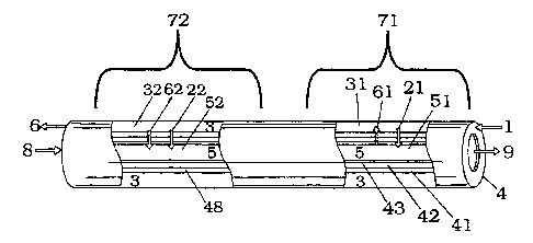
invention may be better understood by reference to the diagram of Figure 1. In
figure 1, a reforming feed 1 containing hydrocarbon and water and/or steam is
supplied to a "reforming zone" 3 of the membrane reactor. A reformer effluent
6
is withdrawn or exits from that side. Compressed air 8 is fed to the
combustion
side 5 of the membrane, and combustion effluent 9 is withdrawn or exits from
that side. In figure 1, the membrane 4 is in the form of a tube and the
reforming
3a
CA 02414657 2002-12-18
r r
side 3 is on the outside of the tube, while the combustion side 5 is on the
inside
of the tube.
Conventional steam reforming reactions are utilized in the reforming
zone 3 to react the hydrocarbon with H2O to form elemental hydrogen and at
least CO. The water and/or steam and hydrocarbon fuel are supplied at
pressures
ranging from about 1 bar to about 300 bars, and preferably from about 5 bars
to
about 40 bars to both facilitate hydrogen permeance through the membrane and
help maintain structural integrity of the membrane 4. The hydrocarbon feed may
comprise any carbon-containing fuel susceptible to thermal or catalytic
reforming and/or shift reaction known in the art to produce hydrogen such as
carbon monoxide, methane and propane.
For hydrocarbon feeds (i.e., those molecules containing only C and
H) there need be at least two moles of water in the feed per moles of carbon
feed. Less water causes incomplete conversion and carbon deposition,
therefore,
it may be desirable to use water feed content ranging from about 1.7 to about
6.0
moles of water per mole of hydrocarbon feed. More preferably, water feed
content ranges from about 2 to about 4 moles of water per mole of hydrocarbon
feed. For general carbon containing feeds, the steam amount is expressed as a
steam to carbon ratio (S/C), which is preferred to be in the range of 1 to 6.
More
preferably, for carbon containing feeds with overall molar composition
expressed as CxHyOZ, the steam to carbon ratio is between (2-zlx) and (3-zlx).
Steam reforming is a highly endothermic reaction. For example,
reforming a simple methane hydrocarbon feed
CH4 + H2O -+ 3H2 + CO
4
CA 02414657 2002-12-18
has a heat of reaction of about 88,630 BTU/mole. One aspect of the present
invention is the utilization of at least a portion of the heat of hydrogen
combustion to supply at least a portion of the heat requirements of the
reformer's
endothermic reaction. To facilitate this, the reforming reaction preferably
occurs
proximate to or most preferably, at the reforming zone surface of the
membrane.
A means to accomplish this is to promote the reforming reaction using a
catalyst
that is contiguous with, or deposited on at least a portion of the membrane 4.
In
one embodiment, a reforming catalyst is deposited onto or into a portion of
the
surface of the membrane. Figure 1 shows a catalyst (41, 48) deposited onto the
surface of the membrane. Examples of materials that are suitable as reforming
catalysts include nobel metals and nobel metal oxides such as Platinum,
Ruthenium, and oxides thereof, transition metals and transition metal oxides
and
generally elements or oxides of group VIII metals as well as Ag, Ce, Cu, La,
Mo, Mg, Sn, Ti, Y and Zn, or combinations thereof Preferred catalyst systems
include Ni, NiO, Rh, Pt and combinations thereof. These materials may be
deposited or coated on the membrane surface or incorporated into the catalyst
surface by means known in the art.
As stated above, the feed fuel and water and/or steam feed are at
pressures ranging from about one (1) to about three hundred (300) bars, and
preferably between about five (5) and forty (40) bars. The operating
temperature
of the membrane will range from about 400 C to about 1400 C with a preferred
operating temperature range of about 700 C to about 1300 C. While the
adiabatic upper temperature limit is about 2000 C, present membrane and gas
turbine technology have an operating Limit of about 1400 C. The operating
temperature on the reforming side of the membrane may be up to about 200 C
cooler than the temperature on the combusting side. A sufficient level of
hydrogen permeance through the membrane is required in the practice of the
invention. Hydrogen permeance under operating conditions will range from
CA 02414657 2002-12-18
about one (1) to about one million (106) moles (mn2-day-atm H2). The permeance
referred to is a point permeance that can be defined at each point on the
membrane surface and the units atmosphere of fI2 refer to the difference
between
the hydrogen partial pressure across the membrane. One skilled in the art will
recognize that hydrogen permeance will be influenced by the hydrogen pressure
differential between the reformer side 3 of the membrane and the combustion
side 5 of the membrane, the temperature of the membrane 4 and/or hydrogen
gas, and strongly influenced by the composition, thickness and configuration
or
shape of the membrane and membrane surface(s). Because of the wide variation
in physical conditions along the length of the membrane, we require that at
least
one region of or on the membrane has a hydrogen permeance in the range from 1
Mole / {Meter2-Day-Atmosphere of H2) to 106 Mole / {Meter2-Day-Atmosphere
of H2). Suitable membrane materials are ceramics such as alumina and zirconia
silicon carbide, silicon nitride, or combinations thereof, including for
example,
A1203, ZrO2, MgO, TiO2, La203, SiO2, perovskites, hexaaluminates, and metals
such as nickel and high nickel content alloys, and cermets.
Membranes may be incorporated into a module. Several
technologies exist to form membrane combustor modules. Membrane modules
provide means to combine multiple membrane elements with a gas distribution
means and with flow passages or channels that bring the gases into close
proximity to the membrane. Membrane elements may be fabricated in many
ways, including as tubes and flat plates. Module technologies suitable for
various membrane elements are known in the art.
Within the module, the membrane may be in the form of a flat sheet
tube, hollow fiber, or may be integrated into a monolithic structure. The
membrane is sealed to or into the module so that the feed and permeate are
separated from each other by the membrane. In a preferred embodiment the
6
CA 02414657 2002-12-18
membrane is sealed into the module so that the feed and permeate streams are
separated. In this embodiment the module provides a method of distributing
and collecting separate feed and permeate streams from individual membrane
elements. The membrane elements may be formed as a symmetric or
asymmetric structure. The membrane may also have a catalytic functionality
incorporated into it. Catalyst functionality may be provided as pelletized or
powder catalyst, supported or unsupported, that is loaded into the gas
passageways proximate to the membrane, or catalyst, supported or unsupported,
may be applied directly to the membrane surfaces, or as a porous layer
integral
with the membrane. Catalyst functionality may be provided in multiple ways and
on either or both sides of the membrane.
In a preferred embodiment, heat exchange membrane 4 comprises an
asymmetric membrane having a relatively porous support or substrate and a thin
separation layer that selectively diffuses hydrogen. The porous support,
illustrated in Figure 1 as 42, provides mechanical strength and structural
integrity as well as facile transport of molecules to the separation layer 43.
The
porous support may be composed of multiple layers of material, each with a
differing chemical composition or pore size. In a preferred embodiment, the
majority of pores in the support are in the range from.05 to 30 gm. Materials
that can be used for supports include alumina, zirconia, silicon carbide, and
porous metals such as porous steel, nickel and alloys such as Hasteloy. The
support structure is preferably stable under high temperature operating
conditions and must not be degraded by molecular species that are utilized or
formed in the process (for example steam). The membrane 4 illustrated in
Figure 1 is comprised of catalyst (41,48), porous support 42, and
permselective
layers 43. Catalysts 41 and 48 may comprise two or more catalysts, one serving
to catalyze the steam reforming reaction, the second to catalyze the water gas
shift reaction.
7
CA 02414657 2002-12-18
c .,
A thin selective diffusion layer, illustrated in Figure 1 as 43, may be
positioned on or into the combustion side surface of the membrane. This is
most
preferable when, for example, hydrocarbon feeds contain materials that would
be
deleterious to such material. The thin selective diffusion layer may comprise
a
thin film of metal such as nickel, or ferrous alloys or inorganic materials
such as
alumina, zirconia, yttrium stabilized zirconia, silicon carbide, silicon
nitride,
perovskites and hexaaluminates ranging in thickness from about 100 angstroms
to 500 microns. The asymmetric configuration facilitates high hydrogen
permeance while maintaining hydrogen selectively and structured integrity
under
the contemplated operating temp -atures and pressures.
In a preferred embodiment, the steam reforming reaction is followed
by a water shift gas reaction on the reformer side 3 of the membrane reactor.
This reaction, generally known to those skilled in the art, converts carbon
monoxide into a carbon dioxide. An idealized reaction is represented by the
formula:
CO+H2O-> H2+CO2
The reaction is mildly exothermic having a heat of reaction of
approximately -17,700 BTU/mole. As practiced in the art; water gas shift is
accomplished in two stages, at high and low temperature, respectively. In the
first (high temperature) stage, the reaction is conducted with chromium
promoted iron catalyst at an inlet temperature of about 370 C. Reaction
exothermically raises the temperature to about 430 C at the exit. A second
stage
of low temperature shift is then employed because equilibrium toward hydrogen
is improved at lower temperature.
8
CA 02414657 2002-12-18
In a preferred embodiment of the present invention, permeation of
hydrogen through the membrane is used to drive the equilibrium, instead of
using lower temperature. This permits deleting the low temperature shift
portion, and permits the user to run the high temperature shift at higher
temperatures. In one embodiment, the catalyst used for steam reforming is also
used to catalyze the shift reaction, and shift and reforming reactions occur
in
parallel according to their individual rates at locations along the reforming
side
of the membrane.
In the preferred embodiment, the feed flow of fuel and steam on the
reformer side is in a direction opposite to the feed flow of air on the
combustor
side. (This arrangement is commonly referred to as counterflow.) Counterflow
is
preferred because it matches the cooling of the carbon dioxide to the pre-
heating
of the combustion air, and is also preferred because it matches the hottest
portion
of the combustion side with the reforming reaction, which is endothermic.
Other
arrangements such as co-flow or crossflow, both generally known in the art,
may
be used, for example for mechanical or chemical reasons.
In a preferred embodiment, the catalyst for the water gas shift
reaction is contiguous with or deposited on at least a portion of the surface
of the
heat exchange membrane. In this embodiment, steam reforming chemistry
occurs first, illustrated as zone 71 in Figure 1, and shift reactions occur
second,
illustrated as zone 72. In zone 71, steam-reforming reactions occur in the
area 31
that is proximate to the membrane, and/or catalyzed by steam reforming
catalyst
41. In zone 72, shift reactions occur in the area 32 that is proximate to the
membrane, and/or catalyzed by shift catalyst 48. In this arrangement, heat 62
released by the shift reaction may be conducted to the combustion side 52
where
it may provide preheat for the incoming air stream 8. Combustion of hydrogen
9
CA 02414657 2002-12-18
in the region 51 of zone 71 provides heat 61 that is conducted to side 31 to
provide the heat of the reforming reaction.
Hydrogen liberated or produced in the reforming reaction and the
water gas shift reaction selectively permeates the membrane 4 to the
combustion
side 5 of the reactor. Selectively permeates, simply stated, means that the
membrane porosity permits the diffusion of the relatively small size hydrogen
molecules through the membrane, while blocking the flow of the other gases.
Flux of hydrogen is from the reforming side 3 to the combustion side 5 and is
illustrated in figure 1 with arrows 21 and 22.
It is preferred that, at areas of maximum hydrogen permeance, the
hydrogen selectivity be at least 3:1 with respect to other gases such as
nitrogen,
oxygen, methane, CO, CO2 and H2O. In a preferred embodiment, the foregoing
selectivity ratio is at least about 100:1. More preferred is a selectivity
ratio of at
least about 10000:1.
The remaining process stream 6 will substantially comprise carbon
dioxide (C02). Having substantially isolated the CO2 stream, this gas stream
may be sequestered by such means as, adsorption. or containment, injection
into
reservoirs such as deep wells, deep ocean injection, and the like. Therefore,
in
accordance with one aspect of the present invention, a process stream
substantially comprised of CO2 is isolated and available for sequestration by
means known in the art.
As stated above, the hydrogen produced or liberated in the reforming
reaction and water gas shift reaction permeates the heat exchange membrane 4
to
the combustion side 5 of the reactor. The hydrogen is then combusted proximate
to the heat exchange membrane 4. This is done to facilitate transfer of the
heat
CA 02414657 2002-12-18
of combustion of the hydrogen through the heat exchange membrane 4, to
supply heat to the reforming reaction. In a preferred embodiment, at least a
portion of the surface or surface region of the combustion side surface of the
heat exchange membrane contains a catalyst for the combustion of hydrogen.
This catalyst is most preferably on a portion of the surface or surface region
of
the membrane 4 that is juxtaposed the region where the stream reforming
reaction occurs.
Catalysts that are suitable for use in the oxidation of hydrogen (i.e.,
combustion) of the invention include mixtures of metals and/or metal oxides
from the transition elements as well as from groups 2a, 3a, and 4a of the
periodic
table (including Lanthanides and Actinides). Such catalysts may take on the
conventional format of catalyst on support, however at the high temperature of
operation utilized for the present invention, catalyst may take the form of a
single mixed-metal oxide formulation, such as a substituted perovskite or
hexaaluminate. Catalyst systems developed for catalytic combustion in gas
turbines are particularly useful in the present invention (for example, see
Catalysis Today, Volume 47, Nos. 1-2(1999)). ]Preferred support materials
include oxides of elements in groups 2a, 3a 3b (including Lanthanides), 4a,
and
4b. More preferred support materials include A1203, TiO2, and ZrO2, especially
as stabilized, for example with rare-earth oxides. Also more preferred are
hexaaluminate supports including LaA111O18, (more generally MA111019-a,, where
M is an element or mixture of elements, for example including La, Ba, Mn, Al
or, Sr). Also more preferred are perovskite supports such as LaCrO3 (more
generally MlM203.a,, where Ml and M2 are each an element or mixture of
elements, for example including Fe, Ni, Co, Cr, Ag, Sr, Ba, Ti, Ce, La, Mn,
Zr).
Substituted hexaaluminate, perovskite, or mixed metal oxide supports may, in
themselves, provide adequate catalytic activity for high temperature oxidation
of
hydrogen. Alternatively, a catalytic agent may be dispersed onto the support.
11
CA 02414657 2002-12-18
Preferred catalyst materials include metals and oxides of elements in groups
6b,
7b, and 8. More preferred catalyst materials include metals and oxides of
elements in groups 6b, 7b, and 8. More preferred catalyst materials are the
group 8 metals and oxides, in particular metals and oxides of Fe, Rh, Pd, and
Pt.
Metals and oxides of Fe and Pd are most preferred for reasons of least
volatility
at high temperatures.
In addition to providing heat to the reforming reaction, the hydrogen
combustion reaction produces energy. In one embodiment, this energy is
utilized to power a turbine for the production of electricity. As illustrated
in
Figure 1, compressed air 8 is fed to the combustion side of the reactor. The
pressure of the compressed air may range from about three (3) bars to about
three hundred (300) bars and preferably between about eight (8) bars and about
fifty (50) bars. Because the combusted fuel is hydrogen, the combustion
produces substantially no carbon dioxide product to be of concern regarding
the
greenhouse effect on the environment. Nor does effluent 9 contain substantial
amounts of carbon monoxide or unburm hydrocarbons of concern to the
environment. In addition, the use of hydrogen as fuel provides wide process
latitude regarding combustion stoichiometry and temperature. Combustion at
relatively lean, cool (compared to stoichiometric combustion) conditions in
proximity to the membrane will produce substantially no nitrogen oxide
products. In this embodiment, the combustion energy powers a turbine for the
production of electricity.
Referring now to Figure 2, there is illustrated a heat exchange
membrane reactor powered turbine for the production of electricity. The
membrane reactor has a reformer side 3 and combustion side 5 separated by a
heat exchange membrane 4. A hydrocarbon plus water (steam) feed 1 is
supplied to the reformer side of the reactor. Hydrogen produced in the
12
CA 02414657 2010-05-18
reforming reaction and the water gas shift reaction permeates membrane 4 to
the
combustion side 5 of the reactor. Compressed air 8 is fed to the combustion
side
3 of the reactor where hydrogen from the reformer : reaction and water gas
shift
reaction has permeated to. The hydrogen is combusted; its combustion energy
released into combustion product 9, which is directed to turbine expander 204.
In some embodiments of the present invention, all or a fraction (215) of the
reforming-side reaction product 6 is combined with combustion effluent 9 as a
combined stream 203 that is directed to the turbine expander 204.Turbine
expander 204 produces power on shaft 206, which power provides the
compressive energy to compress air stream 201 via compressor 202, and which
power is used to produce electricity in generator 207. The expanded combustor
effluent 205 contains waste heat that can be recovered by raising steam and
preheating feeds. In this embodiment; waste heat boiler 212 removes heat from
the combustor effluent 205, and provides that heat to boiler feed water 211 to
raise steam 213 that is fed to the reforming side of the reactor. Cooled
combustor
effluent may be discharged to the atmosphere.
The reforming effluent 6 may be used in several ways. In a
preferred embodiment, it is cooled in heat exchanger 216, increased in
pressure
via compressor 220, and finally sequestered as stream 221. Depending on
steam/carbon ratios and other operating parameters, liquid water may need to
be
removed at some point in the cooling, compressing and sequestering of the
reforming effluent. Such removal is well known in the art. In some
embodiments, a portion 217 of the cooled reforming effluent is made into a
higher pressure stream 219 via compressor 218 and is recycled to the reformer
feed. The combined reformer feed 1 consists of hydrocarbon feed 214, steam
213, and optionally recycled reformer effluent 219. The combined stream is
preferably heated prior to introduction into the reactor, for example using
heat
exchanger 232. Heat exchanger 232 could be a furnace or could be heat
13
CA 02414657 2002-12-18
recovery from effluent streams such as 6 or 205, some combination of furnace
and heat recovery. Arranging such heat recovery is well known in the art.
A differential pressure (AP) may exist between reforming side and
the combustion side of the membrane. Differential pressure is characterized in
two ways; the magnitude of the pressure difference and the sign of the
pressure
difference (which stream is higher pressure). Both of these characteristics
may
vary with application.
In some embodiments of the present invention, it will be preferred
for the reformer to be at higher pressure than the combustor. For example,
when
the objective is to combust methane and leave a sequesterable CO2 stream, it
may be preferred to have the reforming side at substantially higher pressure
than
the combustion side. When the pressure of the reformer is higher than the
combustor, the magnitude of that pressure difference is preferred to be less
than
about 100 bar.
In some embodiments of the present invention, it will be preferred
for the combustor to be at higher pressure than the reformer. For example,
when
the objective is to use a low pressure fuel gas as turbine fuel without
expending
the cost of compressing that fuel gas, it may be preferred to have the
reforming
side at substantially lower pressure than the combustion side. In such an
embodiment, a near-surface combustion of hydrogen on the combustor side
creates a local low H2 partial pressure, which enables transfer of the H2 from
the
low-pressure reformer side to the high-pressure combustor side. When the
pressure of the combustor is higher than the reformer, the magnitude of that
pressure difference is preferred to be less than about 50 bar.
14
1741.
CA 02414657 2002-12-18
When the magnitude of the pressure difference is large (for either
sign), then there may be debits associated with the required mechanical
strength
and the differences between volumetric flow rates between the two sides. For
example, large pressure differences call for devices physically capable of
supporting the forces associated with the high differential pressure. In some
embodiments, the incentive of large differential pressure will justify the
added
complexity and cost of the configuration, in other applications it may not.
Thus,
for some embodiments, it is preferred that the differential pressure (AP)
between
reforming side and the combustion side of the membrane be less than about 5
bars. For some embodiments it is preferred that the differential pressure (AP)
between reforming side and the combustion side of the membrane be less than
about 20% of the higher of the two pressures.
The present invention may operate with feeds that may contain
hydrocarbons, oxygenates, CO, CO2, nitrogen, hydrogen, H2S, sulfides,
mercaptans, and thiophenes. Other trace components may also be present in the
feed. The product from the reformer side will contain CO2 and H2O. A
substantial portion of the H2O exiting the reformer originates as feed. The
CO2
in the gas exiting the reformer is the sum of the net amount produced in the
reforming reaction and the amount originating with the feed. Other
components that can be present are products that can be produced in the
reforming reaction such as CO and hydrogen. The nitrogen level in the reformer
product will be determined by the nitrogen level in the feed. The level of H2S
in
the product gas from the reformer will be determined by the amount of sulfur
in
the feed.
The ability to produce a stream that has a significant CO2
concentration is one aspect of the invention. A significant CO2 concentration
can be produced when the feed contains less than about 35 mole % nitrogen and,
CA 02414657 2002-12-18
in a preferred embodiment, less than 5 mole % nitrogen. When there is a
substantial amount of C02 in the product gas, it may be economically disposed,
stored, or utilized in underground formations. For example, product CO2 may be
utilized as an enhanced recovery fluid in oil reservoirs or may be sequestered
in
depleted oil or gas reservoirs. Certain aquifer formations are suitable for
storing
or sequestering CO2. Because of the pressures in underground formations, in
most cases the CO2 has to be injected at high pressures. The cost of
compression
is substantially reduced when the stream exiting the reformer is substantially
composed of CO2. To minimize the cost of compression, it is advantageous to
have the CO2 rich stream exit the reformer at pressures above 100psi and more
preferable at pressures above 250 psi.
Another aspect of the invention is the potential to operate the
membrane combustor in a mode that produces less NOR. NOR production in
combustion is generally associated with high temperatures. It is possible to
operate the membrane combustor at temperatures lower than those normally
required to sustain a flame. Lower temperature operation is possible because
hydrogen is burned in the membrane combustor rather than a hydrocarbon.
Hydrogen can be combusted under conditions where hydrocarbons will not
normally react. The combustion of hydrogen may also be facilitated by a
catalyst, allowing reaction at highly rich or lean conditions. When the
membrane combustor is operated in a mode designed primarily for NOR
reduction, it may be possible to combine the product streams exiting the
reformer and combustion sides. Recombination of these streams may occur
within the membrane module or after the streams exit the membrane module and
before they are fed into a gas turbine.
By way of illustration, the following exemplify embodiments of the
present invention.
16
CA 02414657 2002-12-18
Example 1:
In the present example, diagrammatically illustrated in Figure 3, methane
is combusted in heat exchanged membrane reactor, the reactor feeds and
effluents being integrated with a gas turbine for power generation. The gas
turbine is comprised of an air compressor 302, a power turbine 304, a shaft
306
and a generator set 307. Air 301 enters the compressor 302 and leaves as a
pressurized stream 358 at a pressure of about 35 atmospheres absolute and a
temperature of about 600 C. The air travels through the heat exchanged
membrane reactor on the combustion side 355 where some of the oxygen reacts
with hydrogen that has permeated the membrane 354. The combustion effluent
359 goes to the power turbine 304 where it is expanded to an atmospheric
pressure stream 305 at a temperature of about 417 C. Component flow rates for
streams 358 and 359 are shown in Table 1. Under these conditions the
compressor 302 uses 100 MW of power and the turbine 304 yields 157 MW for
a net gas turbine power yield 307 of 57 Megawatts.
The reforming side 353 of the heat exchanged membrane reactor is fed by
a methane/steam stream. 351 at a steam/methane mole ratio of 2.5 and preheated
to 490 C. Within the reactor, the methane is completely converted to hydrogen
and C02, the hydrogen permeating to the combustion side 355. The CO2 and a
residual amount of steam comprise the product stream 356 of the reforming side
353. Component flow rates for streams 351 and 356 are shown in Table 1. In the
present example, 1.326 kg/sec of H2 is created and permeated through the
membrane 354.
17
CA 02414657 2002-12-18
Table 1
Stream Flows, kg/sec
Reformer Reformer Combustor Combustor
Feed Product Feed Product
Figure 3 Identifier 351 356 358 359
02 0.000 0.000 37.025 26.420
N2 0.000 0.000 121.875 121.875
CH4 2.651 0.000 0.000 0.000
H2O 7.457 1.491 0.000 11.931
C02 0.000 7.291 0.000 0.000
Total 10.108 8.783 158.900 160.226
Temperature, C 490 800 600 1224
The reformer feed 351 is preheated by recovering heat from several
sources. The power turbine exhaust 305, at about 417 C is used in a waste heat
boiler 312 to make steam 313 from boiler feed water 311. The cooled exhaust
308, now at about 325 C is then used in heat exchanger 336 to heat the methane
fuel 314 from pipeline temperatures of about 25 C to about 250 C, leaving the
final flue-gas 335 at about 316 C . The heated methane 330 and the steam 313,
both at about 250 C are combined into a feed stream 331, which is heated in
heat
exchanger 332 against the reformer effluent stream 356. The resulting
preheated
reformer feed 351 is at about 490 C, while the cooled reformer effluent stream
333 is at about 300 C. This reformer effluent stream 333 is further cooled in
air
fin heat exchanger 316 to condense water and cool to about 50 C. Compressor
320 is used to raise this CO2 stream to a high-pressure stream 321 suitable
for
sequestration.
In this example, the gas turbine net power 307 of 57 MW represents about
43% of the lower heating value of the methane feed 314. This compares
favorably with the cycle efficiency of the gas turbine as used with a normal
18
CA 02414657 2002-12-18
combustor. Because the cooled CO2 efuent 334 is highly concentrated and at
high pressure, the additional work required to compress to sequestration
pressures is minimal. For example, compression to 160 bar would require less
than a megawatt of power. Also, the flue gas 335 at about 317 C would be
suitable for generation of additional power via combined cycle operation.
Example 2
The membrane combustor module shown in Figure 4 is formed from
asymmetric tubular membranes 401. The tubular membranes are sealed into the
module in a geometry similar to a tube in shell heat exchanger. Each tabular
membrane is sealed at each end into a plate (403 and 405) in a manner such
that
gas can pass directly through the plate into the interior 407 of each tube.
The
plates (403 and 405) are in turn sealed into a ceramic tube 409 that forms the
shell of the module. The ceramic tube 409 has fittings (411 and 413) that
allow
gas to be flowed inside the shell. At the ends of the module there are flanges
(417 and 419) that allow the module to be sealed to inlet and exit pipes.
Compressed air 415 in the pressure range of 5 to 40 atmospheres is fed
into the shell through fitting 411. The compressed air 415 entering the shell
is in
the temperature range from 25 to 10000 Centigrade. It is preferred that the
compressed air be in the temperature range from 200 to 600 C. In general air
will heat to these temperature ranges when it is compressed.
Within the shell space of the module 421, the oxygen in the compressed
air reacts with hydrogen permeating the asymmetric tubular membranes 401,
releasing heat and forming water vapor. It may be desirable to catalytically
assist the reaction of oxygen and hydrogen. In this example the reaction is
catalyzed with a platinum catalyst that is dispersed on the exterior surface
423 of
19
CA 02414657 2002-12-18
the asymmetric membranes 401. The catalyst can be deposited from solution
using standard dispersed metal catalyst preparation methods. When the catalyst
is incorporated on the membrane surface 423, there is a tendency to have more
of the exothermic water forming reactions occur on the membrane surface. This
improves the thermal integration with the steam reforming and shift reactions
that occur on the interior surface of the asymmetric membrane. Alternatively,
other methods may be used to incorporate catalyst into the shell side 421 of
the
membrane. Catalyst can be incorporated into the shell space of the module 421
as pellets, monoliths or as a coating covering the entire interior shell
surface.
Whether a catalyst is used or not, it is preferable to have a substantial
portion of the hydrogen permeating the membrane react with oxygen in the
compressed air. As the compressed air travels down the length of the module
from the inlet port 411 to the exit port 413, it heats up. The air and water
vapor
exiting the module 425 are preferably at a temperature in the range from 700
to
1400 C. This hot high-pressure air and water vapor stream 425 is fed to a gas
turbine where electric power is produced.
In the interior of the tubular asymmetric membranes, a feed 427
containing H2O and methane is flowed in a direction that is countercurrent to
the
hot high pressure air and water vapor stream 425. The hydrocarbons and sulfur
species in the feed 427 come from natural gas. The feed 427 also contains a
portion of the reformed gas exiting 429 the tubular membranes. The reformed
gas 429 is primarily composed of C02 and H20. A portion of this gas is
recycled back to the input 427 to add C02 to the feed The addition of C02
helps suppress carbon deposition within the tubular membrane. In particular,
it
helps control carbon deposition caused by the Boudart reaction. It is
preferred
that the amount of gas recycled back to the feed. 427 be .1- 50 volume % of
the
amount of natural gas fed It is more preferred that the amount of gas recycled
CA 02414657 2002-12-18
back to the feed be in the range of 2-20 volume %. The molar ratio of H2O to
CH4 in the feed, also known as the steam/methane ratio can range from 1 to 6.
The steam/methane ratio is preferred to be greater than 2. When the
steam/methane ratio is between 1 and 2, all of the carbon cannot be converted
to
C02 and a syngas product can be produced.
The feed 427 pressure of the gas mixture used to fuel the membrane
combustor can be in the range from 1-200 atmospheres. It is preferred that the
gas mixture be in the range from 2-50 atmospheres. The inlet temperature of
the feed 427 can be in the range from 20-700 C. It is more preferred that the
feed is a single-phase, gaseous stream at temperature above 250 C.
As the feed gas 427 travels countercurrently to the compressed air stream
(415 and 425), it heats up. As the feed gas heats up it begins to react to
form
hydrogen. The initial reaction will be predominantly a steam reforming
reaction
that can be promoted by a catalyst. Further down the module, CO formed by
the initial steam reforming reaction is converted to hydrogen and CO2 with a
water gas shift reaction. This reaction can be catalyzed with a catalyst that
is
different from the catalyst use to promote the reforming reaction. The
catalyst
for these reactions can be on the inner surface of the tubular membrane,
within
the wall of the tubular membrane of introduced as catalyst pellets within the
interior 407 of the tubular membrane.
In this example, the membrane combustor module is formed from tubular
membrane elements 401. The tubular membranes can have an inner diameter
in the range from .1 to 25 millimeters and a wall thickness of.1-10
millimeters.
It is preferred that the tube wall 431 be porous. The porous wall improves
transport of hydrogen across the membrane and also provides structural
strength.
The most prevalent pore size is in the range from.01 to 100 m. In this
21
CA 02414657 2002-12-18
example the porous tube is made by sintering alpha alumina powder. A thin
membrane that is permselective for hydrogen is formed near or on the inner or
outer surface of the tube. In this example, the permselective hydrogen
membrane is formed on the outer surface of the tube. The hydrogen selective
membrane in this example is a 1 gm, thick layer of dense alpha alumina. At the
operating temperature of the membrane combustor module, the alpha alumina
readily transports hydrogen.
Example 3
This example follows the same flow diagram and conditions as Example
1, except that it has been adjusted for a feed that has a high level of CO2.
The
feed in this case has a molar C02/CH4 ratio of 2.65. The high level of CO2 in
the
feed results in a higher heat capacity for the reformer effluent 356, which,
in
turn, means that the reformer feed 351 may be heated to a higher temperature.
In this case, a reformer feed temperature of 610 C is achieved, as shown in
Table 2 below. The added CO2 diluent results in additional small changes in
the
heat balance that result in a the need for slightly higher methane feed rate,
but
also provide a slightly higher flow rate to the power turbine. The combination
of
these changes results in an efficiency decrease of about 0.4% relative to
Example 1. Thus, power is extracted from a highly C02-diluted stream while
maintaining the CO2 at high concentration and pressure suitable for subsequent
sequestration, and without substantial loss in efficiency.
22
CA 02414657 2002-12-18 -
Table 2
Stream Flows, kg/sec
Reformer Reformer Combustor Combustor
Feed Product Feed Product
Component
02 0.000 0.000 37.025 26.304
N2 0.000 0.000 121.875 121.875
CH4 2.680 0.000 0.000 0.000
H2O 7.539 1.508 0.000 12.062
H2 0.000 0.000 0.000 0.000
CO2 19.562 26.933 0.000 0.000
Total Stream 29.781 28.441 158.900 160.240
Temperature, C 610 800 600 1224
23