Note: Descriptions are shown in the official language in which they were submitted.
CA 02414867 2002-12-20
OR File No.9-13523-30CA
- 1 -
SLIP SPOOL AND METHOD OF USING SAME
FIELD OF THE INVENTION
The present invention relates to slip assemblies
for supporting tubing in a wellbore, and more particularly
to a slip spool used to selectively sizpport a tubing string
during a live well operation.
BACKGROUND OF THE INVENTION
In the oi-~w industry slips have been essential
components of oil field drilling and servicing equipment
for many years. Conventional slips are sets of heavy hinged
blocks with gripping dies that are positioned in a slip
bowl of a rotary table to engage tubing, such as drill
pipe, casing or production tubing suspended in a wellbore.
Angled surfaces in each slip block mate with angled
surfaces in the slip bowl. The angled surfaces cause axial
forces exerted on the slip blocks by the weight of the
tubing to be transferred into lateral gripping pressure on
the tubing. The gripping pressure supports the tubing and
prevents it from slipping down through the slips into the
wellbore.
As is well known in the art, conventional slips are
manually engaged by oil field persor.inel who maneuver the
slips into the slip bowl so that they slide into engagement
with a casing, drill or production tubing pipe. The slips
are disengaged by upward axial movement of the casing,
drill pipe, or production tubing to remove weight from the
slips. The slips are then lifted out of the slip bowl. An
example of such conventional slips is described in United
CA 02414867 2002-12-20
OR File No.9-13523-30CA
- 2. -
States Patent 4,244,093, entitled 7URBINE SLIP PULLING
TOOL, which issued to Klingsensmith on January 13, 1981.
There is al:i ever increasing demand for producing
more oil and gas from existing wells. After a primary
recovery term of a well has expired, some form of reworking
is required to produce at least a por=tion of the remaining
oil and/or gas frorri the well. In reworking a well, such as
in preparation for a well stimulation process, the tubing
string must be removed from the well or pulled up to permit
the tubing hanger to be removed so that stimulation fluids
can be pumped down through an annulus between the
production tubing and the casing. During such operations
the tubing string is supported as required, by slips. It is
therefore necessary to set and remove the slips during
preparation for a well stimulation process. Consequently,
slips are not only frequently used during well drilling and
completion, they are also essential equipment for well
re-completion, servicing and workover.
It has been increasingly apparent that well serving
and workover are best performed under "live well"
conditions. A live well is a well in which downhole
pressure are controlled by wellhead equipment. As is well
known, slip assemblies generally do not provide pressure
seals to inhibit the escape of hydrocarbons from the well.
Consequently, the use of slip assemblies over a live well
generally requires either the use of hydril blowout
preventers in conjunction with. ram-type blowout preventers,
to control well pressures unless the well is "killed" by
pumping in a overbearing fluid, such as drilling mud to
prevent fluids from escaping from the well. Either option
contributes significantly to treatment costs. Each option
CA 02414867 2007-08-28
File No.9-13523-30CA
- 3 -
also has other disadvantages. For example, killing a well
can reverse the beneficial effects of a well stimulation
process. On the other hand, the use of one or more hydril
blowout preventers significantly raises working heights,
making the well more difficult to work and compromising
worker safety.
There therefore exists a need for a pressure
containing slip spool that integrates into a wellhead
control stack to overcome the shortcomings of the prior art
slip assemblies, while being robust and reliable enough to
support even very long strings of coiled or jointed tubing.
SUNIlKARY OF THE INVENTION
An object of the present invention is to provide a
pressure containing slip spool for selectively supporting a
tubing string suspended in a wellbore, which integrates
into the wellhead control stack and has a height that does
not interfere with well servicing operations.
Another object of the invention is to provide an
apparatus for selectively supporting a tubing string
suspended in a wellbore, which can be operated under well
pressure while significantly improving operator safety.
The invention therefore, provides a slip spool that
can be mounted to a wellhead for selectively supporting a
tubing string suspended in the wellbore. The slip spool has
an axial passage that is aligned with the wellbore for
permitting a tubing string to extend therethrough, and at
least two radial passages extending through a side wall of
the slip spool and communicating with the axial passage.
The radial passages extend inwardly and downwardly at a
CA 02414867 2002-12-20
OR File No.9-13523-30CA
- 4 -
first angle relative to a central axis of the axial
passage. Each of the radial passages accommodates a slip
assembly that is slidably received within the radial
passage. Slip jaws are pivotally mounted to and slidable
together with respective slip anchors of the slip
assemblies. The slip spool further includes means for
moving the respective slip anchors with the slip jaws
between an extended position in which the respective slip
jaws are inserted into an annulus between the tubing string
and the axial passage for gripping the tubing string, and a
retracted position in which the slip jaws clear the axial
passage to provide full bore access through the slip spool.
Each slip jaw has a gripping surface and a bearing
surface forming a~-,econd angle therebetween which is more
acute than the first angle. The axial passages through the
sidewall of the slip spool preferably comprises a slip seat.
for each slip jaw. The slip seat extends at an angle with
respect to an axis of the axial passage. The angle is
substantially equal to the second angle defined by the slip
jaw. The bearing surface of each of the slip jaws rests on
the slip seat of the slip spool, and the gripping surface
of each of the slip jaws grips an exterior surface of the
tubing string when the slip jaws are in the extended
position. Thus, axial forces exerted by the tubing string
on the slip assemblies are transferred into lateral
gripping pressure on the tubing string, thereby supporting
the tubing string and preventing the tubing string from
slipping through the slip jaws.
In one embodiment of the present invention a link
member pivotally interconnects each slip jaw to its
corresponding slip anchor. Each link member pivots about a
CA 02414867 2007-08-28
File No.9-13523-30CA
- 5 -
first and second pivot axes. The first and second pivot
axes are parallel to each other and are perpendicular the
axis of the corresponding radial passage so that the slip
jaw is permitted to move slightly downward relative to the
longitudinal axis of the radial passage, under the weight
of the tubing string when the slip anchor is in its
extended position and the slip jaw rests on the slip jaw
seat. This permits the slip jaw to lodge into the annulus
between the slip seat and the exterior surface of the
tubing string, thereby providing a secure support to the
tubing string. Actuators mounted on the slip spool
reciprocate the slip assemblies within the respective
radial passages.
The slip spool is adapted to be sealingly mounted
to a wellhead of a live well, and the slip spool in
accordance with the invention permits slips to be set or
released in a convenient and safe manner under live well
fluid pressures. The slip spool in accordance with the
invention also has a low profile, which is convent to work
around. Slip spool in accordance with the invention can
also be invented in a control stack and used to snub tubing
in high-pressure wells when fluid pressure overbears string
weight.
Other advantages and features of the present
invention will be better understood with reference to
preferred embodiments of the present invention described
hereinafter.
BRIEF DESCRIPTION OF THE DRAWINGS
Having thus generally described the nature of the
present invention, reference will now be made to the
CA 02414867 2002-12-20
OR File No.9-13523-30CA
- 6 -
accompanying drawings, showing by way of illustration the
preferred embodiments thereof, in which:
FIG. 1 is a partial cross-sectional view of a slip
spool in accordance with one embodiment of the present
invention, showing a slip assembly in a retracted position;
FIG. 2 is a partial cross-sectional view of the
slip spool shown in. FIG. 1, illustrating the slip assembly
in an extended position, with a slip jaw of the slip
assembly seated on a slip seat formed in the radial passage
of the slip spool;
FIG. 3 is a partial cross-sectional view of a slip
spool in accordar.ice with another embodiment of the
invention, showing the slip assem:bly in a retracted
position;
FIG. 4 is a partial cross - sectional view of the
slip spool shown in FIG. 3, illustrating the slip assembly
in the extended position with the slip jaw seated on the
slip seat formed in the radial passage: of the slip spool;
FIG. 5, which appears on sheer 7 of the drawings,
is a partial cross--sectional view taken along line 5-5 of
FIG. 2, showing key and groove engagement between a slip
anchor with a circular cross-section and a radial passage
that slidably receives the slip anchor;
FIG. 5a, which likewise appears on sheet 7 of the
drawings, is a partial cross-sectional view similar to
FIG. 5 showing a slip anchor with a square cross-section
slidably received within a radial passage, in accordance
with an alternative embodiment of the invention;
CA 02414867 2007-08-28
File No.9-13523-30CA
- 7 -
FIG. 6 is a cross-sectional view of a wellhead
equipped with the slip spool illustrated in FIG. 1 being
used in a procedure for installing a tubing hanger with
attached tubing string in a tubing head spool on a live
well;
FIG. 7 is a partial cross-sectional view of a
wellhead equipped with the slip spool illustrated in FIG. 1
being used in a procedure for installing a tubing hanger
with attached tubing string in a tubing head spool on a
live well, without using a service rig;
FIGs. 8 and 8a are cross-sectional views of a
wellhead equipped with the slip spool shown in FIG. 1 being
used in a procedure for inserting a mandrel of a blowout
preventer protector connected to a tubing string through
the wellhead without using a service rig; and
FIG. 8b is a partial cross-sectional view of a
lower portion of a wellhead in which a mandrel of a blowout
preventer protector equipped with a sealing nipple is
inserted by the equipment illustrated in FIGs. 8 and 8a, in
order to seal off against a casing of the well.
DETAILED DESCRIPTION OF THE PREFERRED EMBODIMENT
The present invention provides a slip spool for
selectively supporting a tubing string suspended in a
wellbore, and methods for using the slip spool during
completion or maintenance procedures. The slip spool can be
used to support a coil tubing string or a jointed tubing
string. The slip spool provides a sealed axial passage and
can be operated under well pressure, so that during a live
CA 02414867 2002-12-20
OR File No.9-13523-30CA
8 -
well procedure it is not necessary to kill the well at any
time.
The slip spool can also be left in place during the
entire well procedure, so that labor is reduced and safety
is improved. The slip spool is useful for any well
completion, re-completion or servicing procedure if tubing
or other components must be run into or out of the well.
Used in conjunction with other pressure containment
components, such as high pressure valves, landing spools,
or tubing adaptors the slip spool. permits live well
operations with only one blowout preventer. Consequently,
well procedure equipment costs are reduced and working
height is reduced. Worker safety is thereby improved and
the work progresses more quickly.
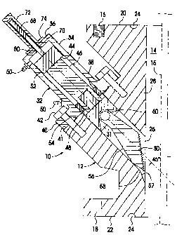
FIGs. 1 and 2 schematically illustrate a slip
spool 10 in accordance with one embodiment of the
invention, in a partial cross-sect.ional view. The slip
spool 10 includes a spool body 12 having an axial
passage 14 that aligns with the wellbore and provides
full-bore access when the slip spool 12 is mounted to a
wellhead. A bottom flange 22 includes mounting bores 18 for
bolting the slip spool 12 to a top of another spool, such
as a blowout preventer (BOP) or the like. A stud pad 20 of
the slip spool 12 includes threaded bores 16 for receiving
studs for mounting another spool, Bowen union or adapter to
a top of the slip spool 12. Annular grooves 24 provided in
the stud pad 20 and the bottom flange 22 respectively
receive a gasket seal (not shown) when the slip spool 12 is
mounted to the wellhead to provide a fluid seal between
adjacent spools in a manner well known in the art.
CA 02414867 2002-12-20
OR File No.9-13523-30CA
9 -
The spool body 12 is also provided with at least
two radial passages 26 (only one shown) that extend through
a side wall 28 and communicate with the axial passage 14.
Each of the radial passages 26 extends inwardly and
downwardly at an angle of, for example, 450 relative to an
central axis of the axial passage 14.
Each radial passage 26 includes a downwardly angled
slip seat 57 for supporting a respective slip jaw 30. The
angle between the slip seat 57 and the axis of the axial
passage 14 is, ~=or example, 26 or less, which is
substantially more acute than the angle between the axis of
the radial passage 26 and the axis of the axial passage 14.
The slip seats 57 are machined at a bottom edge of the
respective radial passages 26, and a conjunctive edge 58 is
formed between each slip seat 57 and each radial
passage 26.
Each radial passage 26 houses a slip assembly that
includes a slip jaw 30 that is pivotally connected to a
slip anchor 31 by a pivot pin 60. The axis of the pivot
pin 60 is perpendicular to the longitudinal axis of the
radial passage 26. The slip anchor 31 is slidably received
in the radial passages 26. Each slip jaw 30 includes a
gripping surface 62 (FIG. 4) and a biasing surface 56. An
angle between the gripping surface 62 and the biasing
surface 56 is substantially equal to the angle between the
slip seat 57 and the central axis of the axial passage 14.
The gripping surface 62 has a transversely curved
configuration that corresponds to an external diameter of a
tubing string 15 that is to be supported by the slip
jaws 30, and the biasing surface 56 is contoured to conform
to the shape of the slip seat 57.
CA 02414867 2002-12-20
OR File No.9-13523-30CA
- 10 -
The slip spool 10 further includes actuators for
moving the respective slip assemblies from a retracted to
an extended position. The actuators may be, for example,
hydraulic actuators 32 (only one shown), for moving the
slip anchors 31 and the slip jaws 30 between the retracted
position as shown in FIG. 1 and the extended position as
shown in FIG. 2. The hydraulic actuators 32 are aligned
with the respective radial passages 26. Each hydraulic
actuator 32 includes a cylinder 34 having an outer end 36
and an inner end 38. A radial flange 40 provided at the
inner end 38 of the cylinder 34 is bolted to a mounting
surface 41 of the side wall 28 of the spool body 12 by
mounting bolts 42. A piston 44 cor.Lnected to a piston
shaft 46 is slidably received in the cylinder 34 and the
piston shaft 46 is guided by a cylinder end plate 48, which
is threadably secured to the inner end of the cylinder 34.
The piston shaft 46 is connected to an outer end of the
slip anchor 31 so that the slip anchor 31, and the
pivotally connected slip jaw 30 move together with the
piston 44. Hydraulic nipples 50 are provided at inner and
outer ends 38, 36 of the cylinder 34 for connecting
pressurized hydraulic fluid lines (not shown) to the
hydraulic actuator 32. 0-ring seals 52 are provided between
the piston 44 and the cylinder 34, and between the piston
shaft 46 and the end plate 48. A gasket seal 54 is also
provided between the radial flange 40 and the mounting
surface 41 of the side wall 28 of the spool body 12.
It should be noted that any other known actuators
can be used instead of the hydraulic actuators 32 for
reciprocating the slip assemblies. For example, mechanical
screws can be used for that purpose, as described in
Applicant's co-pending Canadian patent application,
CA 02414867 2007-08-28
File No.9-13523-30CA
- 11 -
entitled SLIP SPOOL AND METHOD OF USING SAME, which was
filed on March 28, 2002 under Serial No. 2,379,497.
Each slip jaw 30 in the retracted position, as
shown in FIG. 1 is received within the corresponding radial
passage 26 of the slip spool, thereby providing full-bore
access to the well through the axial passage 14. The slip
jaw 30 moves towards and eventually extends into the axial
passage 14 of the slip spool 12 as the piston 44 is moved
inwardly under hydraulic fluid pressure. After the bearing
surface 56 of the slip jaw 30 reaches the conjunctive
edge 58 of the axial passage 14 and the corresponding
radial passage 26, the slip jaw 30 pivots about the pivot
pin 60 and slides over the conjunctive edge 58 while moving
together with the slip anchor 31 and the piston 34 until
the slip jaw 30 is in the extended position, as shown in
FIG. 2. In this extended position, the bearing surface 56
of the slip jaw 30 rests on the slip seat 57 and the
gripping surface 62 (FIG. 4) of the slip jaw 30 abuts the
exterior surface of the tubing string 15. After the weight
of the tubing string 15 is released against the gripping
surface 62 of the slip jaw 30, the slip jaw 30 is moved
slightly downwardly over the slip seat 57, thereby
transferring the weight of the tubing string 15 exerted on
the gripping surface 62 into a lateral gripping pressure on
the tubing string 15 to support the tubing string 15 in the
wellbore. After the slip jaws 30 reach the extended
position but before the weight of the tubing string 15 is
exerted on the slip jaws 30, the hydraulic actuators 32 are
left unlocked in order to permit a position of the
respective slip anchors 31 to adjust as the slip jaws 30
are drawn downwardly over the slip seat 57.
CA 02414867 2002-12-20
OR File No.9-13523-30CA
- 12 -
The slip anchor 31 is also inhibited from
rotating while being moved reciprocally in the radial
passage 26, in order to ensure that: the slip jaw 30 is
correctly seated on the slip seat 57 and that the gripping
surface 62 correctly mates with an outer surface of the
production tubing 15. In accordance with one embodiment of
the present invention, as shown iri FIG. 5, the radial
passage 26 and the slip anchor 31 has a circular
cross-section and keys 64 secured in keyways in the slip
anchor 31 are slidably received in longitudinal grooves 66
formed in the sidewall of the radial passage 26. In
accordance with another embodiment of the invention, as
illustrated in FIG. 5a, the radial passage 26 has a square
or rectangular cross-section, as does and the slip
anchor 31 that reciprocates within the radial passage 26.
With reference again to FIGs. 1 and 2, in order to
provide a visual indication of a position of the slip
jaw 30, an indicato:r shaft 68 is connected on its inner end
to the piston 44 and reciprocates through a central bore 70
in the outer end 36 of the hydraulic cylinder 34 within a
tubular sheath 72, which is aligned with the central
bore 70 and is mounted to the outer end 36 of the
cylinder 34 by a mounting plate 74. A sight window 76
(FIG. 2) in the wall of the tubular sheath 72 permits the
outer end of the indicator shaft 68 to be viewed as the
indicator shaft 68 moves with the piston 44. Indicator
marks 78 may be provided on the tubular sheath 72 to
indicate the position of the associated slip jaw 30 with
respect to the axial passage 14. An 0-ring 80 is provided
between the indicator shaft 68 and the central bore '70 of
the outer end 36 of the cylinder 34 to inhibit hydraulic
fluid leakage.
CA 02414867 2002-12-20
OR File No.9-13.523-30CA
- 13 -
FIGs. 3 and 4 schematically illustrate a slip
spool 11 in accordance with to a further embodiment of the
invention. The slip spool 11 is similar to the slip
spool 10 illustrated in FIGs. 1 and 2, and similar
components and features which are indicated by similar
numerals are not redundantly described.
Unlike the slip spool 10 in which the slip jaws 30
are pivotally connected to the respective slip anchors 31
by pivot pins 60, slip spool 11 includes link members 84
for pivotally interconnecting the respective slip jaws 30
and slip anchors 31. Each link member 84 is pivotally
connected at a first end to the slip anchor 31 by a pivot
pin 81, and is pivotally connected at an opposite end to
the slip jaw 30 by means of a pivot: pin 82. The axes of
pivot pin 81 and pivot pin 82 are parallel to each other,
and perpendicular to the axis of the radial passage 26.
In the retracted position shown in FIG. 3, the link
member 84 is not necessarily aligned with the axis of the
radial passage 26 because of the weight of the slip jaw 30.
When the piston 44 of the actuator 32 moves the slip
assembly towards the extended position, and after the slip
jaw 30 contacts the conjunctive edge 58 of the axial
passage 14, the bearing surface 56 of the slip jaw 30
slides over the conjunctive edge 58 until a lower portion
of the gripping surface 62 contacts the exterior surface of
the tubing string :15. As the slip anchor 31 continues to
move down along the radial passage 26, the slip jaw 30
pivots until the entire gripping surface 62 of the slip
jaw 30 contacts the exterior surface of the tubing
string 15 and the bearing surface 56 of the slip jaw 30 is
seated on the slip seat 57, as shown in FIG. 4. When the
CA 02414867 2002-12-20
OR File No.9-13523-30CA
- 14 -
weight of the tubing string 15 is released, the downward
pressure of the axial force causes a slight downward
movement of the slip jaws 30, which is transferred by the
wedge shape of the slip jaws 30 into a lateral gripping
pressure on the tubing string 15. The link member 84
pivotally interconnecting the slip jaw 30 and the slip
anchor 31 provides extra freedom for the slight downward
movement of the slip jaw 30, to compensate for variations
in the diameter of the production tubing.
Slip spools 10 and 11 illustrated in FIGs. 1-4 may
be provided with three or more slip jaws 30 spaced
circumferentially about the central passage 14 of the slip
body 12.
FIG. 6 illustrates a procedure for using the slip
spool 10, 11 described above to install a tubing hanger 100
in a tubing head spool 102, or to remove the tubing hanger
100 from the tubing head spool 102. As is well known in the
art, the tubing hanger 100 must be set in the tubing head
spool 102 in order to suspend the production tubing
string 104 in the wellbore after the production tubing
string 104 has been run into the well during well
completion, as described in Applicant's co-pending Canadian
patent application Serial No. 2,338,097, entitled METHOD
AND APPARATUS FOR INSERTING A TUBING HANGER INTO A LIVE
WELL, which was filed on February 23, 2001. It is also well
known that the tubing hanger 100 must be removed from the
tubing head spool 102 when a mandrel of a BOP protector is
to be inserted through the wellhead (see FIGs. 8 and 8a),
as explained, for example, in Applicant's co-pending
Canadian patent application Serial No. 2,303,058 entitled
BLOWOUT PREVENTER PROTECTOR AND METHOD OF USING SAME, which
CA 02414867 2002-12-20
OR File No.9-13523-30CA
- 15 -
was filed on March 28, 2000. It is also well knowr.i that
slips are required to be set and removed to support the
tubing string 104 during many other well completion, re-
completion and maintenance procedures, particularly if the
procedure requires any manipulation of the tubing
string 104.
The slip spool 10 permits slip jaws 30 to be
extended or retracted under fluid pressures in a live well
without killing the well. The apparatus 10 is mounted to a
top of a BOP 101, for example which is mounted to=a top of
a tubing head spool 102. Mounted on the top of the slip
spool 12 is a Bowen union 106, well known in the art.
A landing oint 108 is adapted to be connected to
the tubing hanger 100. The landing joint 108 is inserted
through a passage 110 of an annular adapter 112, as
described in Applicant's co-pending Canadian patent
application No. 2,303,058 referenced above. The passage 110
includes a packing cavity at a top thereof, which retains a
steel packing washer 114. A high pressure packing 116, such
as a chevron packing, is retained above the steel packing
washer 114. The high pressure packing 116 closely surr=ounds
and provides a high pressure seal around the landing
joint 108 in order to ensure that well. fluids do not escape
to atmosphere when the tubing hanger 100 is inserted into,
or removed from the tubing head spool 102. The high
pressure packing 116 is retained by a gland nut 118. A
safety nut 120 threadedly engages a spiral thread on an
outer periphery of the top end of the annular adapter 112.
A top wall of the safety nut 120 projects inwardly to cover
the gland nut 118 in order to ensure that the gland nut 118
CA 02414867 2002-12-20
OR File No.9-13523-30CA
- l6 -
is not stripped by fluid pressures exerted on the high
pressure packing 11.6.
A side wall of the annular adapter 112 includes at
least two eyes or hooks 122 which receive chain or
cable 124 that is connected to a hoisting mechanism, such
as a boom truck (not shown), in order to suspend the
annular adapter 112 while the landing joint 108 is
connected to a top end of the tubing hanger 100.
Although FIG. 6 shows only one step of the process,
in which apparatus 10 is in its retracted position, the
slip jaws 30 of the apparatus 10 are in the extended
position (see FIGs 2 and 4) to support the tubing
string 104 after the tubing string 104 is run into the well
during the well completion procedure. The slip jaws 30
transfer the axial force exerted on the gripping surface 62
by the weight of the tubing string 104, into a lateral
gripping pressure on the tubing string 104 when the wedge
shaped slip jaws 30 are forced downwardly against the slip
seat 57, as explained above.
A retrievable plug (not shown) seals the tubing
string 104 to prevent well fluids within the well from
flowing out through the tubing string 104. A top end of the
tubing string 104 extends up through the slip spool 12 to
at least near a top of the Bowen union 106. After the
tubing hanger 100 is connected to the top of the tubing
string 104, the annular adapter 112 with the landing
joint 108 extending therethrough, is hoisted above the
wellhead.
The landing joint 108 is then connected to the top
end of the tubing hanger 100, and the annular adapter 112,
CA 02414867 2002-12-20
OR File No.9-13523-30CA
- 17 -
which is suspended from the cables 124 by the boom truck,
or a service rig is lowered and slides down the landing
joint 108 so that a lock nut 126 of an annular adapter 112
can be threadedly engaged with the Bowen union 106.
0-rings 128 around the annular adapter 112 seal the
interface between the annular adapter 112 and the Bowen
union 106. Thus the axial passage 14 of the slip body 12 is
sealed against leakage when the bleed ports 130 of the
annular adapter 112 are closed.
Pressure is then equalized between an annulus of
the live well below the tubing rams of the BOP 101 arld the
axial passage 14 of the slip spool 12, which communi.cates
with the annular adapter 112, using a bleed hose (not
shown) connected between the pressure bleed ports 130 on
the annular adapter 112 and valves 132 of the tubing head
spool 102. After the pressure is equalized and the
respective valves are closed, the tubing rams of the
BOP 101 are opened in order to permit the tubing hanger 100
to be lowered into the tubing head spool 102.
The landing joint 108 is connected to a lifting
mechanism, such as the boom truck of the service rig (not
shown) so that the landing joint 108 and the entire tubing
string 104 can be lifted by operating the boom truck of the
service rig to remove the weight of the tubing string 104
from the slip jaws 30 of the apparatus 10. When the landing
joint 108 is lifted slightly, the slip jaws 30 are
released, and are free to be moved to the retracted
position, as shown in FIG. 6, by operating the hydraulic
actuators 32 to clear the axial passage 14 of the slip
spool 12. The retracting of slip jaws 30 is performed under
well pressure because the tubing rams of the BOP 101 are
CA 02414867 2002-12-20
OR File No.9-13523-30CA.
- 18 -
fully opened. This permits the tubing hanger 100 to be
lowered together with the tubing string 104 in one stroke
through both the slip spool 12 and the BOP 101, until the
tubing hanger 100 is seated in the tubing head spool 102.
Once the tubing hanger 100 is seated in the tubing head
spool 102, lock bolts 134 are adjusted to lock the tubing
hanger 100 within the tubing head spool 102.
The landing joint 108 is then rotated to disconnect
it from the tubing hanger 100, and the landing joint 108 is
pulled up by the boom truck or the service rig until the
landing joint 108 is above the blind rams of the BOP 101.
After the blind rams of the BOP 101 are closed, pressure is
vented from the annular adapter 11.2 by, for example,
opening the pressure bleed ports 130. Subsequently, the
annular adapter 112, the Bowen union 106 and the slip
spool 10, if desired, can be removed by the boom truck.
The tubing hanger 100 can be removed from the
tubing head spool 102 by performing the above-described
process in reverse.
FIG. 7 illustrates another example of using the
slip spool 10 in a rigless well servicing operation to
install the tubing hanger 100 in the tubing head spool 102
or remove it from the tubing head spool 102. Apparatus 10
is illustrated only in one step of the process in which the
slip spool 10 is in its retracted position. In this
example, a BOP 140 replaces the conventional BOP 101 shown
in FIG. 6. The BOP 140 includes a BOP spool 142 having
tubing rams and blind rams similar to those of a
conventional BOP. A pair of bi-directional prime movers,
such as hydraulic cylinders 144 are secured to opposite
sides of the BOP spool 142. The BOP 140 is described in
CA 02414867 2002-12-20
OR File No.9-13523-30CA
- 19 -
Applicant's co-pending Canadian patent application entitled
SPOOL FOR PRESSURE CONTAINMENT USED IN RIGLESS WELL
COMPLETION, RE-COMPLETION, SERVICING OR WORKOVER, filed on
December 31, 2001 under Serial No. 2,363,710.
The procedure described below with reference to
FIG. 7 is similar to the procedure described above with
reference to FIG. 6, and similar steps are not described.
The principal difference between the procedure described
with reference to FIG. 6 and this procedure is that the
lifting and lowering of the tubing hanger 100 and the
tubing string 104 are accomplished by operating the
hydraulic cylinders 144 of the BOP 140, rather than using a
boom truck or a"ervice rig. The landing joint 108 is
rotatably suspended from and supported by a lifting
beam 146, which is mounted to the top of the hydraulic
cylinders 144. Extension rods 148, 150 are connected
between the base plate 146 and hydraulic cylinders 144. The
annular adapter 112 and the landing joint 108 are lowered
to permit the lower end of the landing joint 108 to be
connected to the top end of the tubing hanger 100, which
has already been mounted to a top of the tubing string 104.
The annular adapter 112 is then further lowered until the
lock nut 126 of the annular adapter 11.2 engages the threads
of the Bowen union 106 and the O-:rings 128 around the
annular adapter 112 seal the interface between the annular
adapter 112 and the Bowen union 106.
The pressure is equalized as described above and
the tubing rams of the BOP 140 are opened to clear the
passage for the tubing hanger 100 to be inserted
therethrough into the tubing head spool 102. The hydraulic
cylinders 144 are actuated to lift the beam 146 and the
CA 02414867 2002-12-20
OR File No.9-13523-30CA
- 20 -
tubing string 104 suspended therefrom in order to remove
the weight of the tubing string 104 from the slip jaws 30
of the slip spool 10. The slip jaws 30 are then retracted
from the extended position to clear the axial passage 14 of
the slip spool 12. The hydraulic cylinders 144 are then
operated to lower the tubing string 104 and insert the
tubing hanger 100 into the tubing head spool 102.
A further example of using the apparatus 10 in a
live well operation is described below with reference to
FIGs. 8 and 8a. FIGs. 8 and 8a illustrate only one step of
the process in which the slip jaws 30 of the slip
spool 10,11 are in the retracted position. A mandrel 160 of
a BOP protector having a pack-off assembly 162 at a bottom
end thereof, is to be inserted through a well head 98 from
which a tubing string 104 is suspended. The tubing
string 104 is supported by the slip jaws 30 of the slip
spool 10,11 which is mounted to a top of the BOP 140 of the
wellhead 98. The apparatus 140 is the same as that
described above with reference to FIG. 7, and is mounted to
a tubing head spool 102. The tubing string 104 is normally
supported by a tubing hanger inside the tubing head
spool 102 but the tubing hanger has been pulled out of the
well in a procedure that is a reverse of the tubing hanger
insertion procedure described with reference to FIG. 7.
Thus, the top end of the tubing string 104, which
is supported by the slip jaws 30 in their extended
condition, extends through the Bowen union 106 to an extent
that a distance from the top of the tubing string 104 to
the top of the Bowen union 106 is greater than the length
of the mandrel 160. The mandrel 160 is equipped with an
annular adapter 166. The annular adapter 166 includes
CA 02414867 2002-12-20
OR File No.9-13523-30CA
- 21 -
packing rings 168 constructed of brass, rubber and fabric
disposed within the annular adapter 166 and secured by a
gland nut 170. The packing rings 168 and the gland nut 170
define a vertical passage of a same diameter as a periphery
of the mandrel 160, to provide a fluid seal between the
mandrel 160 and the annular adapter 166.
The mandrel 160 is connected at its top end to a
connector 172 that includes a base plate 174. The
connection of the top end of the mandrel 160 to the
connector 172 is described in detail in Applicant's co-
pending patent applications referenced above. The
connector 172 further includes a lock nut 176 for
engagement with the external threads of the annular
adapter 166. A fracturing head 178 having a central
passage 180, and at least two radial passages 182, is
mounted to the top of the base plate 174. Two high pressure
valves 184 are mounted to the fracturing head 178 to close
the respective radial passages 182. The combination of the
fracturing head 178 and the base plate 174, with all other
components attached thereto is hoisted above the
wellhead 98. The mandrel 160 is then aligned with the
tubing string 104 and is lowered over the tubing string 104
until the pack-off assembly 162 at the bottom end of the
mandrel 160 is inserted into the axial passage 14 of the
slip spool 12 above the slip jaws 30 and the annular
adapter 166 is received in the Bowen union 106. The lock
nut 169 of the annular adapter 166 is then connected to the
Bowen union 106 to securely lock the annular adapter 166 to
the Bowen union 106. The 0-rings 167 seal the int.erface
between the annular adapter 166 and the Bowen union 106.
The top of the tubing string 104 which has a pin
CA 02414867 2002-12-20
OR File No.9-13523-30CA
- 22 -
thread 186, extends above the top end of the fracturing
head 178.
A tubing adapter 188 is then connected to the top
end of the tubing string 104. The tubing adapter 188 is
also connected to the top of the fracturing head 178.
Extension rods 148 of an adequate length are then connected
at their lower end to the piston ram 150 of the respective
hydraulic actuators 144 and at their upper end to the: base
plate 174 using bolts 190 and a connector 192. After the
base plate 174 is connected to the hydraulic cylinders 144,
a high pressure valve 194 (partially shown) can be hoisted
by the boom truck (not shown) to the top of the tubing
adapter 188. The high pressure valve 194 is then mounted to
the top of the tubing adapter 188.
At this stage the slip spool 10 is in its extended
position, and the weight of the tubing string 104 is
supported by the slip jaws 30 of the apparatus 10 by the
gripping pressure exerted on the tubing string 104. In
order to retract the slip jaws 30 to clear the axial
passage 14 of the slip spool 12, the weight of the tubing
string 104 must be removed by operating the hyd:raulic
actuators 144 to extend piston rams 150 to raise the base
plate 174. This is done after the well pressure is
equalized across the BOP and the tubing rams (not shown) of
the BOP 142 are opened.
After the tubing rams of the BOP 140 are opened and
the slip jaws 30 are moved to the retracted poaition (as
shown in FIG. 8a), the cylinders 144 are operated to lower
the mandrel 160 down through the slip spool 12 and the
BOP 140. When the mandrel 160 is in an operating position,
the bottom end of the pack-off assembly 162 is seated
CA 02414867 2007-08-28
File No.9-13523-30CA
- 23 -
against a bit guide 196 (FIG. 8A) connected to a top of the
well casing 198, and provides a seal to isolate the
wellhead components from stimulation fluid pressures.
The mandrel 160 has optional and variable-length
extension sections. Thus, the assembled mandrel 160
including the pack-off assembly 162, is pre-adjusted in
length to ensure that the lock nut 176 can be threadedly
engaged with the annular adapter 166 when the pack-off
assembly 162 is seated against the bit guide 196.
A conventional BOP without hydraulic cylinders, for
example, the BOP 101 illustrated in FIG. 6, may be used in
place of the BOP 140 shown in FIG. Ba. If so, the base
plate 174 is connected to a service rig or a mandrel
injection tool adapted to stroke the mandrel down through
the wellhead.
FIG. 8b illustrates a variation of the well
stimulation procedure described with reference to FIGs. 8
and 8a. The mandrel 160 is inserted into a live well with
the tubing string 104 suspended by the slip jaws 30 of the
slip spool 10 mounted on the wellhead as shown in FIG. 8a.
The bottom end of the mandrel 160 is extended into the well
casing 198 and seals against the well casing 198. A sealing
assembly 200 attached to a bottom end of the mandrel 160
includes at least one cup having a resilient depending
skirt, as described in Applicant's co-pending United States
Patent 6,626,245, issued September 30, 3003 for a BLOWOUT
PREVENTER PROTECTOR AND METHOD OF USING SAME. When the
sealing assembly 200 is inserted into the well casing 198,
the cup of the sealing assembly 200 radially expands under
well pressure against an inner surface of the
CA 02414867 2002-12-20
OR File No.9-13523-30CA
- 24 -
well casing 198, thereby sealing against the well
casing 198. Otherwise, the equipment and tools are the same
as used in the cperation described with reference to
FIGs. 8 and 8a and the procedure for using the slip
spool 10,11 is the same.
Although the invention has been described with
reference to well completion, re-completion and maintenance
procedures in which slips are required to support the
weight of a tubular string in a well bore, the slip spool
10,11 is useful in any application in which a tubing string
must be temporarily suspended in a wellbore.
As will be understood by those skilled in the art,
the orientation of the slip spool 10,11 in a well control
stack is immaterial to its function. Consequently, in high
pressure well conditions the slip spool 10,11 can be
installed in a inverted orientations and used as a snubbing
spool. Likewise, two slip spools 10,11 can be stacked in
opposite orientation to provide both snubbing and slip
control of a tubing string. Because the slip spools 10,11
are pressure containment spools that can be constructed to
any desired pressure rating, well servicing procedures in
which production tubing is controlled using the slip spool
are significantly simplified, proceed more quickly and more
safely.
The embodiments of the invention described above
should be understood to be exemplary only. Modifications
and improvements to those embodiments of the invention may
become apparent to those skilled in the art. The foregoing
description is therefore intended to be exemplary rather
than limiting, the scope of the invention is intended to be
limited solely by the scope of the appended claims.