Language selection

Search

Patent 2414975 Summary

Third-party information liability

Some of the information on this Web page has been provided by external sources. The Government of Canada is not responsible for the accuracy, reliability or currency of the information supplied by external sources. Users wishing to rely upon this information should consult directly with the source of the information. Content provided by external sources is not subject to official languages, privacy and accessibility requirements.

Claims and Abstract availability

Any discrepancies in the text and image of the Claims and Abstract are due to differing posting times. Text of the Claims and Abstract are posted:

  • At the time the application is open to public inspection;
  • At the time of issue of the patent (grant).
(12) Patent: (11) CA 2414975
(54) English Title: ARRANGEMENT FOR CHECKING THE CLAMPING FORCE OF THE COUPLING ARRANGEMENT FOR A TRANSPORTING MEANS OF A CABLEWAY SYSTEM
(54) French Title: MOYEN DE VERIFICATION DE LA FORCE DE SERRAGE DU DISPOSITIF DE RACCORDEMENT D'UN MOYEN DE TRANSPORT PAR CABLE
Status: Expired and beyond the Period of Reversal
Bibliographic Data
(51) International Patent Classification (IPC):
  • B61B 12/06 (2006.01)
  • B61B 12/12 (2006.01)
  • G01L 05/00 (2006.01)
(72) Inventors :
  • FUCHS, ELMAR (Austria)
(73) Owners :
  • INNOVA PATENT GMBH
(71) Applicants :
  • INNOVA PATENT GMBH (Austria)
(74) Agent: SMART & BIGGAR LP
(74) Associate agent:
(45) Issued: 2008-01-29
(22) Filed Date: 2002-12-20
(41) Open to Public Inspection: 2003-11-10
Examination requested: 2004-11-26
Availability of licence: N/A
Dedicated to the Public: N/A
(25) Language of filing: English

Patent Cooperation Treaty (PCT): No

(30) Application Priority Data:
Application No. Country/Territory Date
A 727/2002 (Austria) 2002-05-10

Abstracts

English Abstract

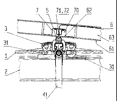
Arrangement for checking the clamping force to which the supporting and haulage cable (1) is subjected by the coupling arrangement for a transporting means of a cableway system, the coupling arrangement being designed with a clamping lever which is subjected to the action of a spring-energy store and on which is mounted an actuating roller (5) which rolls along a running surface (61) of a guide rail (6), the running surface being designed with an elastically deformable region (62) which is assigned a measuring arrangement (7) by means of which it is possible to measure the deformation of the running surface (61) on account of t:he compressive force which is produced by the spring-energy store, acts on the guide surface via the actuating roller (5) and corresponds to the clamping force. In this case, the measuring arrangement (7) is formed by at least two measuring units (71, 72) which function in different ways.


French Abstract

Dispositif de vérification de la force de serrage à laquelle le câble porteur-tracteur (1) est soumis par le dispositif de raccordement d'un moyen de transport par câble, le dispositif de raccordement étant conçu avec un levier de serrage qui est soumis à l'action d'un accumulateur d'énergie à ressort et sur lequel est monté un galet d'actionnement (5) qui roule le long d'une surface de roulement (61) d'un rail de guidage (6), la surface de roulement étant conçue avec une région déformable de façon élastique (62) qui est pourvue d'un dispositif de mesure (7) au moyen duquel il est possible de mesurer la déformation de la surface de roulement (61) en raison de la force de compression qui est produite par l'accumulateur d'énergie à ressort, agit sur la surface de guidage au travers du galet d'actionnement (5) et correspond à la force de serrage. Dans ce cas, le dispositif de mesure (7) est formé par au moins deux unités de mesure (71, 72) qui fonctionnent de manière différente.

Claims

Note: Claims are shown in the official language in which they were submitted.


CLAIMS
1. Apparatus for checking the clamping force to which a supporting and
haulage cable (1) is subjected by a coupling arrangement of a transporting
assembly in a cableway system, the coupling arrangement being designed with a
clamping lever (51) and a spring-energy store acting on said clamping lever on
which clamping lever there is mounted an actuating roller (5) which rolls
along a
running surface (61) of a guide rail (6), the running surface being designed
with
an elastically deformable region (62) which is assigned a measuring
arrangement (7) by means of which it is possible to measure the deformation of
the running surface (61) on account of compressive force which is produced by
the spring-energy store and acts on said running surface via the actuating
roller
(5) and corresponds to the clamping force, characterized in that the measuring
arrangement (7) is formed by at least two measuring units (71, 72) which
function in different ways.
2. The apparatus as claimed in claim 1, characterized in that the at least two
measuring units (71, 72) are designed for different oscillator frequencies.
3. The apparatus as claimed in claim 1 or claim 2, characterized in that the
at least two measuring units (71, 72) are arranged one beside the other in a
movement direction of the actuating roller (5).
4. The apparatus as claimed in claim 1 or claim 2, characterized in that the
two measuring units (71, 72) are arranged one behind the other in a movement
direction of the actuating roller (5).
5. The apparatus as claimed in any one of claims 1 to 4, characterized in that
at least three measuring units (71, 72) are provided, these being arranged one
beside the other or one behind the other in a movement direction of the
actuating roller (5).
6. The apparatus as claimed in any one of claims 1 to 5, characterized in that
the at least two measuring units (71, 72) are formed by inductive transducers,
having oscillators with mutually different frequencies.
-7-

7. The apparatus as claimed in any one of claims 1 to 5, characterized in that
the at least two measuring units (71, 72) are formed by capacitive
transducers,
having oscillators with mutually different frequencies.
8. The apparatus as claimed in any one of claims 1 to 5, characterized in that
the at least two measuring units (71, 72) are formed by ultrasound units
having
mutually different frequencies at oscillation.
9. The apparatus as claimed in any one of claims 1 to 5, characterized in that
the at least two measuring units (71, 72) are formed by light-measuring units
which operate at different pulse frequencies.
10. The apparatus as claimed in any one of claims 1 to 9, characterized in
that
one of the measuring units (71, 72) is designed as an inductive transducer, as
a
capacitive transducer, as an ultrasound generator or as a light-measuring
unit.
-8-

Description

Note: Descriptions are shown in the official language in which they were submitted.


CA 02414975 2002-12-20
Arrangement for checking the clamping force of the coupling
arrangement for a transporting means of a cableway system
The present invention relate;_~ to an arrangement for checking
the clamping force to which the supporting and haulage cable
is subjected by the coupling arrangement for a transporting
means of a cableway system, ~.he coupli.ng arrangement being
designed with a clamping levcar which is subjected to the
action of a spring-energy store and on which is mounted an
actuating roller which rolls along a running surface of a
guide rail, the running surface being designed with an
elastically deformable region which is assigned a measuring
arrangement by means of whic:ln it i~; possib:Le to measure the
deformation of the running slrface on account of the
compressive force which is produc:ect by the spring-energy
store, acts on said running surface via the actuating roller
and corresponds to the clamping force.
An arrangement which is intended for checking the clamping
force of a coupling arrangement a.ncl in the case of which the
clamping force of the coupling arrangement to which the
supporting and haulage cable is subjected by the spring-energy
store is checked by the provision of a second spring-energy
store by means of which, in t=he ca~~e where the compressive
force applied by the first s~~ring-energy st=ore is not
sufficient, an actuating lever is ~~ivoted, the latter
actuating a switch for switcOing off the cableway system, is
known.
This arrangement for checking the clamping force, however,
gives rise to a very high maintenar:ce outlay.
-1-

CA 02414975 2002-12-20
An electronically acting arrangement for checking the clamping
force is also known. In the case of this arrangement, a region
which can be elastically deformed under the action of the
compressive force exerted by an actuating roller arranged on a
pivotable clamping lever is provided on the running surface of
a guide rail for the actuating roller, said region being
assigned an electronic measuring unit by means of which it is
possible to measure the deformation of this region. Since the
extent to which this region of the running surface is deformed
is dependent on the magn:itudE>. of the compressive force to
which the running surface is subjected by the actuating
roller, said compressive force, for its part, corresponding to
the magnitude of the clamping force to which the supporting
and haulage cable is subjected by the coupling arrangement,
the clamping force can be detvermined and/or checked by the
electronic measuring unit.
Although this known arrangement i.s advantageous in comparison
with mechanical clamping-force checking, it does not fulfil
the existing requirements since the sought-after functional
reliability is not ensured by G ~>ingle electronic measuring
unit. The supposedly obvious solution to this problem, of
providing a plurality of electronic measuring units for
determining the deformation 3f the measuring region of the
running surface, is not applicable since the electronic
measuring units influence one another, as a result of which
the necessary functional reliabilit=y is not achieved.
The object of the present invention is thus to provide an
arrangement for checking t=he clamping force electronically by
means of which the disadvantages a:~sociated with the known
arrangement are avoided. This is achieved according to the
invention in that the measuring arrangement is formed by at
least two measuring units which function in different ways.
-2--

CA 02414975 2002-12-20
Since the measuring units tht:s do not disrupt one another, the
necessary functional reliability is ensured.
The at least two measuring units preferably operate at
different oscillator frec~uenc:ies. It is possible here for the
at least two measuring units to be arranged one beside the
other in the movement direction of the actuating roller or one
behind the other in t:he moverc~ent direction of the actuating
roller. Furthermore, it .is also possible to provide three
measuring units which are arranged one beside the other and/or
one behind the other in the movement direction of the
actuating roller, as a resul.i. of wr.ich the functional
reliability is yet further increased.
According to further-preferred embodiments, the at least two
measuring units are formed b~y inducaive transducers or by
c.apacitive transducers, of which the oscil_Lators are designed
for different frequencies. Furthermore, the at least two
measuring units may be formed by ultrasound units, of which
the oscillator frequencies are di.ff:erent. In addition, the at
least two measuring units mav~ be formed by light-measuring
units which operate at different pulse frequencies. In this
case, in each case one of the unite is de signed as an
inductive transducer, as a capaci.tive transducer,as an
ultrasonic generator and/or as a light-measuring unit.
A measuring arrangement according t=o the invention is
explained in more detail hereinbelow with reference to an
exemplary embodiment illustrated in the drawing, in which:
Fig. 1 shows a side view of a system for checking the
clamping force of the coupling arrangements with a measuring
arrangement according to the inveni~ion;
~3-

CA 02414975 2002-12-20
Fig. 2 shows a detail from fi.g. 1 on an enlarged scale, and
F'ig. 3 shows the measuring arrangement in a different view
from Fig. 2 and on a larger :kale than the latter.
Fig. 1 illustrates a system -t~or determining the clamping force
which is applied by the spring-energy store of coupling
arrangement and acts on the support=ing and haulage cable 1 of
a cableway system. This system has a running rail 2 for the
running-gear mechanism 3 of a tran~~porting means 4 arranged on
a load-bearing bar 41. Provided on the running-gear mechanism
3 are running rollers 31 whi~~h allow the transporting means 4
t:o be displaced along the rails 2 provided in the stations.
Also provided on the running-gear mechanism 3 is a coupling
arrangement which allows the transporting means 4 to be
coupled to the supporting and haulage cable 1.
The movable coupling jaw is designed with an actuating lever
which is subjected to the action o:E a spring-energy store and
which applies the clamping force necessary for the coupling to
the supporting and haulage cable 1. Mounted at the free end of
the actuating lever is an actuating roller 5, which rolls
along a control rail 6. A measurin~~ arrangement 7 is provided
in order to check the clamping force applied by the spring-
energy store. In the case where the clamping force is not
sufficient, the cableway system is switched off by the
measuring arrangement 7.
Such a system is known from the prior art.
As can be seen from Fig. 2, the measuring arrangement 7
according to the invention consists in that a region 62, which
can be elastically deformed, is provided in the running
surface 61 of the control rail 6 for the actuating roller 5 of
-4-

CA 02414975 2002-12-20
the coupling lever, said region 62 of the running surface 61
being assigned two measuring units 71, 72. The control rail 6
is of T-shaped design, and cc;mprises a web 63 and the running
surface 61 arranged thereon. The web 63 is absent in the
region of the measuring units 71, 72 and the two measuring
units 71,72 are arranged in the resulting cutout 70. In the
region 62, the running surface 61, since it is not supported
by the web 63, can be deformed under the action of the spring-
energy store acting on the actuating roller. 5, this resulting
in the distance between said running surface and the measuring
units 71, 72 changing. This change in distance, which
constitutes a measure of the compressive force or of the
clamping force, can be detected by the electronic measuring
units 71, 72, as a result of which it is possible to check the
clamping force.
In order to ensure the sou.ght.-after functional reliability, it
is necessary to provide a plurality of measuring units,
although it is neces~>ary to Eensure that. these do not influence
one another in terms of funca:ionina.
As can be seen from Fig. 3, two measuring units 71 and 72 are
provided, these being arranged one beside the other
transversely to the running direction of the actuating roller
mounted on the coupling lever ~~l and the outputs of the
measuring unit being attached to a control unit 70. In order,
nevertheless, to ensure that they function independently of
one another, these two electronic: measuring units 71 and 72
have to have different oscillator frequencies. 330 kHz and
360 kHz are used, in particular, a~~ the oscillator
frequencies. It is possible here to select the oscillator
frequencies within a very wine range. The critical factor is
for the frequencies of the measuring units arranged one beside
_ 5 _.

CA 02414975 2002-12-20
the other to differ, in order thus to prevent said measuring
units from influencing one another.
The electronic measuring units used may be inductive
transducers, capacitive transducers and ultrasonic generators,
of which the oscillation frequencies are different in each
case. In addition, it: is possible to use light-measuring units
which are operated at differEmt pulse frequencies. It is
possible here to use either t=he same types of measuring units
operated at different frequencies or different types of
measuring units, e.g. an indaactive transdur_er and a capacitive
transducer.
The measuring units may be arranged one beside the other
transversely to the movement direction of the actuating roller
or one behind the other in the movement direction of the
actuating roller 5. A greater number of measuring units
increases the reliability of the measuring result.
The outputs of the measuring units 71 and 72 are attached to
the control and evaluating circuit 70. If the evaluation of
the measuring results establishes an insufficient clamping
force, the cableway system is switched off by the control and
evaluation circuit 70.
-6-

Representative Drawing
A single figure which represents the drawing illustrating the invention.
Administrative Status

2024-08-01:As part of the Next Generation Patents (NGP) transition, the Canadian Patents Database (CPD) now contains a more detailed Event History, which replicates the Event Log of our new back-office solution.

Please note that "Inactive:" events refers to events no longer in use in our new back-office solution.

For a clearer understanding of the status of the application/patent presented on this page, the site Disclaimer , as well as the definitions for Patent , Event History , Maintenance Fee  and Payment History  should be consulted.

Event History

Description Date
Time Limit for Reversal Expired 2021-08-31
Inactive: COVID 19 Update DDT19/20 Reinstatement Period End Date 2021-03-13
Letter Sent 2020-12-21
Letter Sent 2020-08-31
Inactive: COVID 19 - Deadline extended 2020-08-19
Inactive: COVID 19 - Deadline extended 2020-08-06
Inactive: COVID 19 - Deadline extended 2020-07-16
Inactive: COVID 19 - Deadline extended 2020-07-02
Inactive: COVID 19 - Deadline extended 2020-06-10
Letter Sent 2019-12-20
Common Representative Appointed 2019-10-30
Change of Address or Method of Correspondence Request Received 2018-01-12
Grant by Issuance 2008-01-29
Inactive: Cover page published 2008-01-28
Pre-grant 2007-10-09
Inactive: Final fee received 2007-10-09
Letter Sent 2007-07-27
Notice of Allowance is Issued 2007-07-27
Inactive: Approved for allowance (AFA) 2007-06-12
Amendment Received - Voluntary Amendment 2007-03-09
Inactive: S.30(2) Rules - Examiner requisition 2006-12-13
Inactive: IPC from MCD 2006-03-12
Letter Sent 2004-12-08
All Requirements for Examination Determined Compliant 2004-11-26
Request for Examination Requirements Determined Compliant 2004-11-26
Request for Examination Received 2004-11-26
Application Published (Open to Public Inspection) 2003-11-10
Inactive: Cover page published 2003-11-09
Inactive: First IPC assigned 2003-03-04
Inactive: IPC assigned 2003-03-04
Inactive: Filing certificate - No RFE (English) 2003-02-06
Letter Sent 2003-02-06
Application Received - Regular National 2003-02-06

Abandonment History

There is no abandonment history.

Maintenance Fee

The last payment was received on 2007-11-16

Note : If the full payment has not been received on or before the date indicated, a further fee may be required which may be one of the following

  • the reinstatement fee;
  • the late payment fee; or
  • additional fee to reverse deemed expiry.

Patent fees are adjusted on the 1st of January every year. The amounts above are the current amounts if received by December 31 of the current year.
Please refer to the CIPO Patent Fees web page to see all current fee amounts.

Owners on Record

Note: Records showing the ownership history in alphabetical order.

Current Owners on Record
INNOVA PATENT GMBH
Past Owners on Record
ELMAR FUCHS
Past Owners that do not appear in the "Owners on Record" listing will appear in other documentation within the application.
Documents

To view selected files, please enter reCAPTCHA code :


To view images, click a link in the Document Description column. To download the documents, select one or more checkboxes in the first column and then click the "Download Selected in PDF format (Zip Archive)" or the "Download Selected as Single PDF" button.

List of published and non-published patent-specific documents on the CPD .

If you have any difficulty accessing content, you can call the Client Service Centre at 1-866-997-1936 or send them an e-mail at CIPO Client Service Centre.


Document
Description 
Date
(yyyy-mm-dd) 
Number of pages   Size of Image (KB) 
Abstract 2002-12-19 1 25
Claims 2002-12-19 2 77
Drawings 2002-12-19 2 46
Description 2002-12-19 6 257
Representative drawing 2003-03-05 1 13
Description 2007-03-08 2 61
Drawings 2007-03-08 2 48
Representative drawing 2008-01-09 1 14
Courtesy - Certificate of registration (related document(s)) 2003-02-05 1 107
Filing Certificate (English) 2003-02-05 1 160
Reminder of maintenance fee due 2004-08-22 1 111
Acknowledgement of Request for Examination 2004-12-07 1 177
Commissioner's Notice - Application Found Allowable 2007-07-26 1 164
Commissioner's Notice - Maintenance Fee for a Patent Not Paid 2020-01-30 1 541
Courtesy - Patent Term Deemed Expired 2020-09-20 1 552
Commissioner's Notice - Maintenance Fee for a Patent Not Paid 2021-02-07 1 545
Fees 2004-11-03 1 30
Fees 2005-10-23 1 29
Fees 2006-10-19 1 31
Correspondence 2007-10-08 1 30
Fees 2007-11-15 1 31
Fees 2008-10-07 1 36