Language selection

Search

Patent 2415057 Summary

Third-party information liability

Some of the information on this Web page has been provided by external sources. The Government of Canada is not responsible for the accuracy, reliability or currency of the information supplied by external sources. Users wishing to rely upon this information should consult directly with the source of the information. Content provided by external sources is not subject to official languages, privacy and accessibility requirements.

Claims and Abstract availability

Any discrepancies in the text and image of the Claims and Abstract are due to differing posting times. Text of the Claims and Abstract are posted:

  • At the time the application is open to public inspection;
  • At the time of issue of the patent (grant).
(12) Patent: (11) CA 2415057
(54) English Title: DISPLACEMENT AND SUPPORT DEVICE FOR A PORTABLE POWER TOOL
(54) French Title: DISPOSITIF DE DEPLACEMENT ET DE SUPPORT POUR OUTIL ELECTRIQUE PORTATIF
Status: Expired and beyond the Period of Reversal
Bibliographic Data
(51) International Patent Classification (IPC):
  • E21B 15/00 (2006.01)
  • B23B 45/14 (2006.01)
  • B25D 17/28 (2006.01)
  • E21B 19/00 (2006.01)
  • E21B 19/08 (2006.01)
  • E21B 19/086 (2006.01)
  • E21C 35/00 (2006.01)
  • F16M 11/00 (2006.01)
(72) Inventors :
  • RICHTER, MARTIN (Germany)
  • GASSER, GERHARD (Austria)
  • MEISENBICHLER, KARL (Austria)
  • NEUPER, KARL (Austria)
(73) Owners :
  • HILTI AKTIENGESELLSCHAFT
(71) Applicants :
  • HILTI AKTIENGESELLSCHAFT (Liechtenstein)
(74) Agent: EUGENE J. A. GIERCZAKGIERCZAK, EUGENE J. A.
(74) Associate agent:
(45) Issued: 2007-11-20
(22) Filed Date: 2002-12-23
(41) Open to Public Inspection: 2003-07-07
Examination requested: 2003-04-04
Availability of licence: N/A
Dedicated to the Public: N/A
(25) Language of filing: English

Patent Cooperation Treaty (PCT): No

(30) Application Priority Data:
Application No. Country/Territory Date
10200309 (Germany) 2002-01-07

Abstracts

English Abstract

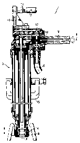
A displacement and support device including a power cylinder provided at its opposite ends, respectively, with an assembly element for connecting the power cylinder with power tool and a support leg, a control valve for controlling operation of the power cylinder , and a manually rotationally adjustable actuation member for actuating the control valve , with the actuation member being formed as a handle extending transverse to an axis of the power cylinder and rotationally adjustable about a handle axis within a rotational angle of 180° that encompasses an entire control region of the control valve.


French Abstract

Un dispositif de déplacement et de support comprenant un vérin de commande fourni à ses extrémités opposées, respectivement, avec un élément d'assemblage pour relier le vérin de commande avec l'outil électrique et une jambe de force, une soupape de commande pour commander le fonctionnement du vérin de commande, et un élément d'actionnement réglable par rotation manuelle pour actionner la soupape de commande, avec l'élément d'actionnement étant réalisé sous forme de poignée s'étendant transversalement à un axe du vérin de commande et réglable par rotation autour d'un axe de poignée dans un angle de rotation de 180° qui comprend une région de commande complète de la soupape de commande.

Claims

Note: Claims are shown in the official language in which they were submitted.


The embodiments of the invention in which an exclusive property or privilege
is
claimed are defined as follows:
1. A displacement and support device for a portable power tool, comprising:
a fluid-operated power cylinder;
assembly means provided at one end of the power cylinder for connecting the
power cylinder with the power tool;
a support leg provided at another, opposite end of the power cylinder;
a control valve for controlling operation of the power cylinder; and
a manually rotationally adjustable actuation member for actuating the control
valve, the actuation member being formed as a handle extending transverse to
an axis
of the power cylinder and rotationally adjustable about a handle axis within a
rotational
angle of 180° that encompasses an entire control region of the control
valve;
wherein the assembly means is formed as a partially torsion-free bolt
connection
element extending transverse to the power tool axis, and projects sideways on
one side
of the one end of the power cylinder and extends through an eyelet provided on
the
power tool.
2. A displacement and support device according to claim 1, wherein the handle-
shaped actuation member is rotationally adjustable within a rotational angle
of 90° that
encompass the entire adjustable region of the control valve.
3. A displacement and support device according to claim 1, wherein the control
valve is formed as a continuously adjustable rotary valve.
6

4. A displacement and support device according to claim 1, wherein the power
cylinder is formed as a double-action cylinder.
5. A displacement and support device according to claim 1, wherein a fluid
conduit
is formed in an interior of the bolt connection element and extends along a
portion of a
longitudinal extent thereof.
6. A displacement and support device according to claim 1, wherein the power
cylinder is hydraulically operated.
7. A displacement and support device according to claim 1, wherein the support
leg
is formed as an elongate member.
8. A displacement and support device according to claim 1, comprising a claw
member securable with a cross-pin for connecting the support leg with another
end of
the power cylinder.
9. A displacement and support device according to claim 1, comprising a
stirrup-
shaped handle rotatably and linearly displaceably mountable on the power
cylinder.
10. A displacement and support device for a portable power tool, comprising:
a fluid-operated power cylinder;
assembly means comprising a partially torsion-free bolt connection element
extending transverse to the axis of the power cylinder for connecting the
power cylinder
with the power tool;
a support leg provided at another, opposite end of the power cylinder;
7

a control valve for controlling operation of the power cylinder;
a manually rotationally adjustable actuation member for actuating the control
valve, the actuation member being formed as a handle extending transverse to
an axis
of the power cylinder and rotationally adjustable about a handle axis; and
a fluid conduit disposed within said assembly means.
11. A displacement and support device according to claim 10 wherein said fluid
conduit is disposed within a portion of said bolt connection element.
12. A displacement and support device according to claim 11 wherein said
handle is
rotatable within a rotational angle of 180°.
13. A displacement and support device according to claim 10 wherein the
control
valve is formed on a continuously adjustable rotary valve.
8

Description

Note: Descriptions are shown in the official language in which they were submitted.


CA 02415057 2002-12-23
BACKGROUND OF THE INVENTION
1. Field of the Invention
The present invention relates to a displacement and support device for a
portable power tool, in particular, a percussion power tool, preferably, for
forming
shot holes during underground mining works.
2. Description of the Prior Art
Such portable power tools, which are driven hydraulically, pneumatically, or
electrically, weight about 15 kg and are usually equipped with an elongate,
water-
flushed drill rod which is rotatably and axially displaceable, within narrow
limits,
secured in the power tool and is provided at its free end with a drill bit
made of a
hard material and having a diameter of about 35 mm.
German Patent DE 74833 discloses a portable electrical rock power drill for
drilling shot holes during underground mining works and provided with an
elongate
water-flushed drilling rod with a drill bit made of hard material, and a
support device.
The drill rod displacement is effected with a hydraulic cylinder of which the
telescopic drill rod forms a part.
U.S. Patent No. 4,000,873 discloses a portable power tool with an easily
mountable displacement and support device which is supported on the ground and
simultaneously applies a controlled displacement force to the drill. For
forming
substantially horizontal holes, the displacement and support device is
inclined
rearwardly and downwardly.
U.S. Patent No. 1,464,486 discloses a rotary-percussion power tool having a
one-leg support and a discretely controlled control valve rotatable about 360
. A
sensitive manual control of the displacement and support device with such a
valve is
not possible.
1

CA 02415057 2002-12-23
U.S. Patent No. 1,151,261 discloses a fluid-driven percussion power tool with
an axially arranged, one-leg support that is formed as a double-action
cylinder and
displacement of which is constantly controlled by a radial, rotationally
adjustable
worm gear valve by effecting several revolutions. For a manual control over
the
entire control region of the displacement and support device, turning over of
the
controlling head is necessary.
An object of the present invention is a displacement and support device that
can be comfortably controlled manually with one hand over its entire control
region.
SUMMARY OF THE INVENTION
This and other objects of the present invention, which will become apparently
hereinafter, are achieved by providing a displacement and support device for a
portable power tool and including a fluid-operated power cylinder, assembly
means
provided at one end of the power cylinder for connecting the power cylinder
with the
power tool; a support leg provided at another, opposite end of the power
cylinder, a
control valve for controlling operation of the power cylinder, and a manually
rotationally adjustable actuation member for actuating the control valve, with
the
actuation member being formed as a handle extending transverse to an axis of
the
power cylinder and rotationally adjustable about a handle axis within a
rotational
angle of 1800 and, preferably, 90 that encompasses the entire control region
of the
control valve.
With the entire control region of the control valve being within a rotational
angle of the actuation member of 180 or 90 , a comfortable control and
fixation of
the displacement and support device becomes possible, without a need to turn
the
controlling hand over and over again.
Advantageously, the continuously controlled control valve is formed as a
2

CA 02415057 2002-12-23
rotary valve, which makes possible to continuously control, in a technological
simple
manner, the flow rate by adjusting the rotary position of the valve.
Advantageously, the power cylinder is formed as a double-action cylinder,
which provides for an easy withdrawal of the drill rod from the bore or hole.
Advantageously, the assembly means is formed as partially torsion-free bolt
connection element extending sideways on outside of the power cylinder and
transverse to the drill axis and through an eyelet provided on the power tool,
securing the power cylinder to the power tool. Within the bolt connection
element,
there is provided a fluid conduit through which fluid, which is fed through
the
pressure hose into the displacement and support device is fed to the power
tool.
The fluid, which enters the displacement and support device flows to the
conduit
through a junction.
Advantageously, the power cylinder is hydraulically operated in which the
water, which is necessary for cooling and flushing the drill bit, is used as a
pressure
medium.
Advantageously, the support leg, which can be formed as an elongate
member, is connected with the power cylinder by a claw member securable with a
cross-pin.
Advantageously, the support device includes a stirrup-shaped handle
rotatably and linearly displaceably mounted on the power cylinder, which
provides
for an easy transportation of the displacement and support device with two
hands.
The novel features of the present invention, which are considered as
characteristic for the invention, are set forth in the appended claims. The
invention
itself, however, both as to its construction and its mode of operation,
together with
3

CA 02415057 2002-12-23
additional advantages and objects thereof, will be best understood from the
following detailed description of preferred embodiment, when read with
reference to
the accompanying drawings.
BRIEF DESCRIPTION OF THE DRAWINGS
In the Drawings:
Fig. 1 shows a schematic view illustrating the use of a displacement
and support device according to the present invention;
Fig. 2 shows a cross-sectional view of a displacement and support
device according to the present invention along line II-II in Fig.
3; and
Fig. 3 shows a side view of a displacement and support device
according to the present invention.
DETAILED DESCRIPTION OF THE
PREFERRED EMBODIMENT
Fig. 1 shows the use of a displacement and support device with a portable
power tool 1 used in underground mining and provided with a rotatably and
percussion driven, water-flushed, elongate drill 2. The displacement and
support
device is formed as power cylinder 3 that supports the power tool 1 against a
floor
and, simultaneously, applies to the drill 2 an acting in the operational
direction of the
drill 2, controlled displacement force. The power cylinder 3, which is
inclined
rearwardly, is manually guided and controlled by a user 5. Water is fed to the
working or power cylinder 3 through a pressure hose 6, and to the drill 2
through the
power tool 1.
The power cylinder 3, which is shown in Figs. 2-3, is formed as a
hydraulically
driven, double-action, power cylinder and is provided, at one of its end, with
an
4

CA 02415057 2006-03-28
ANItNUtU SHtt I
assembly element 7 easily securable to the power tool I and, at another of its
end,
with a support leg 8. The power cylinder 3 is manually controlled by a control
valve
which is formed as a rotary valve. The operation of the control valve 10 is
controlled by a manually rotationally adjustable actuation member 9. The
actuation
member 9 is formed as a handle extending transverse to the axis A of the power
cylinder 3 and rotatable about the handle axis B. The actuation member 9 is
rotationally adjustable within a rotational angle of 180 .
The assembly element 7 is formed as a partially torsion-free bolt connection
element extending sideways transverse to the drill axis and through an eyelet
16
to provided on the power tool 1, securing the power cylinder 3 to the power
tool 1.
Within the bolt connection element, there is provided a fluid conduit 11
through
which fluid, which is fed through the pressure hose 6 into the displacement
and
support device, is fed to the power tool 1. The fluid, which enters the
displacement
and support device, flows to the conduit 11 through a junction 12.
The support leg 8 is secured to another end of the power cylinder 3 by a claw
14 that can be tangentially withdrawn. The claw 14 is secured by a cross-pin
13. A
pivotable and linearly displaceable stirrup shaped handle 15 is provided on
the
power cylinder 3.
Though the present invention was shown and described with references to
the preferred embodiment, such is merely illustrative of the present invention
and is
not to be construed as a limitation thereof and various modifications of the
present
invention will be apparent to those skilled in the art. It is therefore not
intended that
the present invention be limited to the disclosed embodiment or details
thereof, and
the present invention includes all variations and/or alternative embodiments
with the
spirit and scope of the present invention as defined by the appended claims.
5

Representative Drawing
A single figure which represents the drawing illustrating the invention.
Administrative Status

2024-08-01:As part of the Next Generation Patents (NGP) transition, the Canadian Patents Database (CPD) now contains a more detailed Event History, which replicates the Event Log of our new back-office solution.

Please note that "Inactive:" events refers to events no longer in use in our new back-office solution.

For a clearer understanding of the status of the application/patent presented on this page, the site Disclaimer , as well as the definitions for Patent , Event History , Maintenance Fee  and Payment History  should be consulted.

Event History

Description Date
Time Limit for Reversal Expired 2017-12-27
Letter Sent 2016-12-23
Grant by Issuance 2007-11-20
Inactive: Cover page published 2007-11-19
Inactive: Final fee received 2007-08-24
Pre-grant 2007-08-24
Notice of Allowance is Issued 2007-06-28
Letter Sent 2007-06-28
Notice of Allowance is Issued 2007-06-28
Inactive: Approved for allowance (AFA) 2007-05-29
Amendment Received - Voluntary Amendment 2007-01-26
Inactive: S.30(2) Rules - Examiner requisition 2006-10-30
Amendment Received - Voluntary Amendment 2006-03-28
Inactive: IPC from MCD 2006-03-12
Inactive: S.30(2) Rules - Examiner requisition 2005-11-04
Amendment Received - Voluntary Amendment 2003-08-20
Application Published (Open to Public Inspection) 2003-07-07
Inactive: Cover page published 2003-07-06
Letter Sent 2003-06-26
Inactive: Agents merged 2003-05-30
Letter Sent 2003-05-12
Inactive: Single transfer 2003-05-01
All Requirements for Examination Determined Compliant 2003-04-04
Request for Examination Requirements Determined Compliant 2003-04-04
Request for Examination Received 2003-04-04
Inactive: IPC assigned 2003-03-13
Inactive: First IPC assigned 2003-03-13
Inactive: IPC assigned 2003-03-13
Inactive: Courtesy letter - Evidence 2003-02-11
Inactive: Filing certificate - No RFE (English) 2003-02-06
Application Received - Regular National 2003-02-06

Abandonment History

There is no abandonment history.

Maintenance Fee

The last payment was received on 2006-11-22

Note : If the full payment has not been received on or before the date indicated, a further fee may be required which may be one of the following

  • the reinstatement fee;
  • the late payment fee; or
  • additional fee to reverse deemed expiry.

Patent fees are adjusted on the 1st of January every year. The amounts above are the current amounts if received by December 31 of the current year.
Please refer to the CIPO Patent Fees web page to see all current fee amounts.

Owners on Record

Note: Records showing the ownership history in alphabetical order.

Current Owners on Record
HILTI AKTIENGESELLSCHAFT
Past Owners on Record
GERHARD GASSER
KARL MEISENBICHLER
KARL NEUPER
MARTIN RICHTER
Past Owners that do not appear in the "Owners on Record" listing will appear in other documentation within the application.
Documents

To view selected files, please enter reCAPTCHA code :


To view images, click a link in the Document Description column (Temporarily unavailable). To download the documents, select one or more checkboxes in the first column and then click the "Download Selected in PDF format (Zip Archive)" or the "Download Selected as Single PDF" button.

List of published and non-published patent-specific documents on the CPD .

If you have any difficulty accessing content, you can call the Client Service Centre at 1-866-997-1936 or send them an e-mail at CIPO Client Service Centre.

({010=All Documents, 020=As Filed, 030=As Open to Public Inspection, 040=At Issuance, 050=Examination, 060=Incoming Correspondence, 070=Miscellaneous, 080=Outgoing Correspondence, 090=Payment})


Document
Description 
Date
(yyyy-mm-dd) 
Number of pages   Size of Image (KB) 
Description 2002-12-22 5 239
Drawings 2002-12-22 3 108
Claims 2002-12-22 2 71
Abstract 2002-12-22 1 19
Representative drawing 2003-03-13 1 21
Description 2006-03-27 5 232
Claims 2006-03-27 3 85
Claims 2007-01-25 3 83
Filing Certificate (English) 2003-02-05 1 160
Acknowledgement of Request for Examination 2003-05-11 1 174
Courtesy - Certificate of registration (related document(s)) 2003-06-25 1 105
Reminder of maintenance fee due 2004-08-23 1 111
Commissioner's Notice - Application Found Allowable 2007-06-27 1 165
Maintenance Fee Notice 2017-02-02 1 178
Correspondence 2003-02-05 1 25
Fees 2004-11-29 1 30
Fees 2005-11-17 1 32
Fees 2006-11-21 1 37
Correspondence 2007-08-23 1 29
Fees 2007-11-18 1 27