Note: Descriptions are shown in the official language in which they were submitted.
CA 02415155 2006-01-23
25145-349
Title
Tensioning Idler
Field of the Invention
The invention relates to tensioning idlers, more
particularly to tensioning idlers having linear motion
and having damping created by linear bearings' and an
arcuate damping member.
Background of the Invention
Most engines used for automobile.s and the like
include a number of belt driven accessory systems which
are necessary for the proper operation of the' engine.
The accessory systems may include an alternator, air
conditioner compressor and a power steering pump.
The accessory systems are generally mounted on a
front surface of the engine. Each accessory having a
pulley mounted on a shaft for receiving power from some
form of belt drive. In =early systems, each accessory was
driven by a dedicated belt that ran between the accessory
and the crankshaft. With improvements 'in belt technology,
single serpentine belts 'are now used in most
applications, routed - among the various accessory
components. The serpentine belt is driven by the engine
crankshaft.
Since the serpentine belt must=be routed to all
accessories, it has 'generally become longer than its
predecessors. To operate properly, the belt is installed
with a pre-determined tension. As it operates, it
1
CA 02415155 2003-01-10
WO 02/10614 PCT/US01/24096
stretches slightly. This results in a decrease in belt
tension, which may cause the belt to slip, causing undue
noise and wear. Consequently, a belt tensioner is
desirable to maintain the proper belt tension as the belt
stretches during use.
As a belt tensioner operates, the belt usually
oscillates due to its interaction with the pulleys. These
oscillations are undesirable, as they cause premature
wear of the belt and tensioner. Therefore, a damping
mechanism is added to the tensioner to damp the belt
oscillations.
Various prior art damping mechanisms have been
developed. They include viscous fluid based dampers,
mechanisms based on frictional surfaces sliding or
interaction with each other, and dampers using a series
of interacting springs. Each relies on a single form of
damping mechanism to perform the damping function. Each
has a pulley and damping mechanism configuration with the
damping mechanism external to the pulley. This created an
unduly large device for the purpose.
The size problem was solved by incorporating the
damping and tensioning mechanism within the diameter of
the pulley, thereby diminishing its overall size.
Representative of the art is U.S. patent no.
5,045,029 (1991) to Dec which discloses a pulley mounted
on a pivot arm biased with a compression spring. A
damping means operates against a pivot arm to damp
oscillations of the pivot arm. The components are
generally contained within an annular space in the
pulley. See also U.S. patent no. 5,073,148 (1991) to Dec
and U.S. patent no. 5,370,585 (1994) to Thomey and U.S.
patent no. 4,696,663 (1987) to Thomey.
The prior art tensioners are complex and comprise
many components. Each of the prior art tensioners
2
CA 02415155 2003-11-03
25145,L349
constrains the pulley to move in an arc as it operates,
requiring clearance space. The prior art pivot
configuration limits the available operating movement range
of the tensioner. Further, a single damping mechanism is
used which further limits the ability of the tensioner to
damp impulses exceeding a given energy.
What is needed is a tensioner having a pulley
housing that moves linearly. What is needed is a tensioner
having linear bearings that impart damping in response to
linear movement of a pulley. What is needed is a tensioner
having damping created by the action of a band engaged with
an arcuate housing surface. What is needed is a tensioner
having all required components packaged within a pulley
diameter. What is needed is a tensioner having all required
components packaged within a pulley annular space. The
present invention meets these needs.
Summary of the Invention
In a broad aspect of the present invention, there
is provided a tensioning idler comprising: a base having a
stop; a housing having a pulley journaled thereto and having
a housing outer surface; a mechanical engagement between the
housing and base, whereby the housing is constrained to move
on a predetermined path; a damping member having a portion
for engaging the stop, the damping member having a damping
surface in sliding contact with the housing outer surface; a
biasing member with an end connected to the damping member
and an other end connected to the housing, the biasing
member disposed outwardly from the housing outer surface;
and whereby when acted upon by a force the housing moves
along the predetermined path pressing the damping member
portion against the stop, the biasing member then resisting
3
CA 02415155 2003-11-03
25145-349
a further movement of the housing, the damping surface in
contact with the housing outer surface damping a housing
movement.
In a second broad aspect, there is provided a
tensioning idler comprising: a base having a stop; a
housing having a housing surface; a mechanical engagement
between the housing and base comprising a first bearing
member mounted to the base and a second bearing member
mounted to the housing in interlocked sliding engagement
with the first bearing member, the first bearing member
comprises rail surfaces wherein a force couple FR acts on the
rail surfaces through the second bearing member; a damping
member having a damping surface in sliding contact with the
housing surface and a portion for engaging the stop; a
biasing member with an end connected to the damping member
and an other end connected to the housing; and whereby when
acted upon by a force the housing moves along the
predetermined path pressing the damping member portion
against the stop, the biasing member then resisting a
further movement of the housing, the damping surface in
contact with the housing surface damping a housing movement.
In a third broad aspect, there is provided a
tensioner comprising: a housing having a frictional sliding
engagement with a base, the housing constrained to move in a
linear path; an arcuate damping member having a frictional
engagement with the housing; a biasing member disposed
outwardly of the housing and engaged with the base and the
arcuate damping member, whereby the biasing member resists a
movement of the housing; and a pulley journaled to the
housing.
3a
CA 02415155 2003-11-03
25145-~349
In a fourth broad aspect, there is provided a
tensioner comprising: a housing having a frictional sliding
engagement with a base; the base comprising at least two
rail surfaces, the rail surfaces engaged with the housing,
the rail surfaces offset from each other with respect to a
pulley axis of rotation; the housing constrained to move in
a substantially linear path by operation of a force couple FR
acting on the rail surfaces through the housing; an arcuate
damping member having a frictional engagement with a housing
outer surface, the arcuate damping member engagable with the
base; a biasing member engaged with the arcuate damping
member and the housing, the biasing member disposed
outwardly of the housing outer surface; and a pulley
journaled to the housing.
In a fifth broad aspect, there is provided a
tensioning idler comprising: a base having a stop; a
housing having a pulley journaled to the housing, the
housing having a housing outer surface; a pivoting
engagement between the housing and base, whereby the housing
is constrained to move in an arcuate path; a damping member
engageable with the stop, the damping member having an
arcuate damping surface in frictional contact with the
housing outer surface; and a biasing member with an end
connected to the damping member and an other end connected
to the housing, the biasing member disposed outwardly of a
housing outer surface.
A primary aspect of the invention is to provide a
tensioner having a pulley housing that moves linearly.
Another aspect of the invention is to provide a
tensioner having linear bearings that impart damping in
response to linear movement of a pulley.
3b
CA 02415155 2003-11-03
25145-349
Another aspect of the invention is to provide a
tensioner having damping created by the action of a band
engaged with an arcuate housing surface.
Another aspect of the invention is to provide a
tensioner having all required components packaged within a
pulley diameter.
Another aspect of the invention is to provide a
tensioner having all required components packaged within a
pulley annular space.
3c
CA 02415155 2003-01-10
WO 02/10614 PCT/US01/24096
Other aspects of the invention will be pointed out
or made obvious by the following description of the
invention and the accompanying drawings.
The invention comprises a tensioner having a linear
motion. A pulley is journaled to a housing. A bearing
is used to slidingly join the housing and a base. The
bearing constrains the housing, and therefore the pulley,
to move along a predetermined path. The housing also
comprises an arcuate damping surface that interacts with
a frictional or damping band. A torsion spring
concentrically engages the frictional material band,
pressing it in to engagement with the arcuate damping
surface as the housing moves in response to an impulse or
force from the pulley. As a belt load impulse causes the
housing to move along the predetermined path, a contact
between the damping band and the base causes the spring
to further press the frictional damping material against
the housing arcuate surface, thereby damping movement of
the housing. Further, an axis of the pulley is offset
from a centerline of the bearing. As the housing moves,
a couple is created between the housing and the base
acting through the bearing. The forces of the couple
create a frictional force between the bearing surfaces,
further damping a movement of the housing and thereby a
movement of the pulley.
Brief Description of the Drawings
The accompanying drawings, which are incorporated in
and form a part of the specification, illustrate
preferred embodiments of the present invention, and
together with a description, serve to explain the
principles of the invention.
Fig. 1 is a side cross-sectional view of the invention at
line B-B in Fig. 2.
4
CA 02415155 2006-01-23
25145-349
Fig. 2 is a partial cross-sectional plan view, of tM,
invention.
Fig. 3 is a free body diagram of the linear bearing.
Fig. 4 is a detail of the guide and rail.
Fig. 5 is a partial cross-sectional plan view of an
alternate embodiment.
Fig. 6 is a cross-sectional elevation view of the pivot
point in Fig. 5.
Detailed Description of the Preferred Embodiment
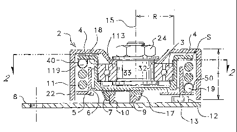
Fig. 1 is a side cross-sectional view of the
invention at line B-B in Fig. 2. The inventive tensioner
comprises pulley 2 journaled to housing 4 with bearing 3.
Bearing 3 is pressed into housing 4 in the preferred
embodiment, but may be mechanically connected by any
suitable means known in the art. Pulley 2 and housing 4
may comprise the idler pulley disclosed in U.S.
Patent No. 6,293,885 filed 3/14/00. As disclosed in
Patent No. 6,293,885, flange 32 of pulley 2 bears upon an inner
race 113 of bearing 3. Axle 33 and nut 24 affix pulley 2
to the inner race of bearing 3.
Bearing member or guide 7 is mounted to-a lower
surface of housing 4. Guide 7 has sides 17 that are
inclined to housing 4 at an acute angle, creating :a "C"
like shape, see Fig. 4. Bearing members or rails 9, 10
are mounted to the base 8. ~Sides 17 of guide 7 are
slidingly engaged with and cooperate with inclined sides
of rails 9, 10. Guide 7 and rails 9, 10 constrain
housing 4 to move substantially linearly as described in
Fig. 2. One can appreciate that guide 7 and cooperating
rails 9, 10 comprise a linear bearing. Although rails 9,
10 are shown' as separate pieces, they may also be
combined to form a single part, so long as the edges of
5
CA 02415155 2003-01-10
WO 02/10614 PCT/US01/24096
the part slidingly engage with guide 7 in substantially
the same manner as rails 9, 10.
Biasing member or spring 11 resists a force or belt
load, BL. Spring 11 encircles damping mechanism support 5.
In the preferred embodiment spring 11 is a torsion
spring. End 19 of spring 11 is affixed to support 5 with
clip 50, see Fig. 2. Frictional material 6 is affixed to
an inner surface of support 5, between support 5 and
housing 4. Frictional material 6 may comprise any known
in the motion damping arts, including but not limited to
Nylon 6/6 or Nylon 4/6 with internal lubricant.
Frictional material 6, in turn, circumfrentially
engages an outer surface 18 of housing 4. Support 5,
frictional material 6 and outer surface 18 of housing 4
are substantially co-axial about pulley axis 15. End 13
of support 5 engages with and bears upon stop or tab 12
on base 8. End 119 of spring 11 is attached to housing 4
with clip 40. It can be readily seen that spring 11,
support 5 and frictional material 6 are compactly
contained within a pulley annular space, S, as well as
within a thickness, t, of the pulley. This
configuration results in the tensioner occupying the
smallest possible space; defined only by the diameter and
thickness of the pulley, while affording an enhanced
range of motion as well as damping impulses of greater
magnitude than prior art dampers.
Fig. 2 is a partial cross-sectional plan view of the
invention. Support 5 and frictional material 6 have a
substantially circular form that is substantially coaxial
with the axis of rotation of the pulley 2.
Rails 9, 10 are shown offset from each other with
respect to an axis B-B. The rails 9, 10 are also radially
eccentrically offset from the axis of rotation 15 of the
pulley. Guide 7 comprises a single piece that engages
6
CA 02415155 2003-01-10
WO 02/10614 PCT/US01/24096
each of the rails 9, 10. Spring 11, support 5 and
frictional material 6 are shown contained within an outer
annular surface 22 of pulley 2. In operation, guide 7 and
therefore housing 4 moves parallel to axis A-A in the
positive and negative directions.
Fig. 3 is a free body diagram of the linear bearing.
In operation, a belt 14 imparts a belt load or force
on pulley 2 as shown in Fig. 2, identified as FL. FL
causes housing 4 to move along axis A-A thereby causing
end 13 of support 5 to press against stop or tab 12.
This motion causes end 19 of spring 11 to move as to
'wind' the spring about the housing, see Fig. 2.
Movement of the housing 4 in direction V will also cause
end 19 to move in direction DV as end 19 tightens about
surface 18. This is because surface 18 is pressed into
damping or frictional material 6 and support 5 by FL.
Consequently, movement of support 5 in direction V pulls
end 19 in direction Dv. It is known in the art that
turning a torsion spring in a direction to wind the
spring or close the coils will cause the spring to resist
such load or movement, assuming the other end of the
spring is fixed. An increased force will result in an
increase in the spring force resisting such force as a
function of the spring rate. For a given number of coils
in a torsion spring, the amount of spring torque, Tsprr
generated by the movement of the housing 4 is a function
of the lever arm distance "e" from axis A-A to the point
of contact of the end 13 on-tab 12.
Further movement of the pulley, and thereby housing
4, in direction V will cause end 19 to further move in
direction DV, further tightening support 5 about surface
18. Therefore, one skilled in the art can appreciate
that load or force FL causes frictional material 6 to bear
upon or to be pressed against the housing surface 18. As
7
CA 02415155 2003-01-10
WO 02/10614 PCT/US01/24096
described above, as FL increases, the support 5 and
frictional material 6 are progressively wrapped about the
surface 18. Further, an increase in force and angular
wrap results in an increase in the frictional force
resisting movement of the housing 4 and thereby movement
of pulley 2. This damps a movement of the housing and
thereby of the pulley.
The inventive tensioner also comprises a further
damping mechanism. In operation, as described above, a
belt under a tension or load is trained about pulley 2
which creates a hubload force FL, which in turn operates
on pulley axle 15 and thereby on housing 4. A spring
force vector FS also operates on support 5 to resist
movement of housing 4. FS is shown as a single vector for
ease of description, although one can appreciate that the
force is distributed across the surface of damping band 6
and arcuate surface 18. A reaction force FR in turn
operates on rails 9, 10 through guide 7. Housing 4
through guide 7 is constrained to move along a fixed path
P between guides 9, 10. One can readily appreciate that
the arrangement of the described force vectors causes the
housing to maintain proper contact between the guide 7
and rails 9, 10, thereby preventing rotation of guide 7.
In the preferred embodiment, the predetermined path P for
the housing is substantially linear. In an alternate
embodiment, described in the following figures, the path
is substantially arcuate.
Since the.tensioner may be assumed to be in static
equilibrium for the purposes of analysis, the various
vectors may be added to give the reaction force vector FR
on the rails 9, 10:
FR = Fs - FL (1)
FR is resolved as a couple FR* acting on rails 9, 10
through guide 7. If forces Fs, FL, are parallel to each
8
CA 02415155 2003-01-10
WO 02/10614 PCT/US01/24096
other, FR*=0. Then a couple FR* will be determined by
spring torque and distance d; FR*d=Tspr=
The sides of rails 9, 10 engaged with the
cooperating sides 17 of guide 7 have a pre-determined
frictional coefficient. Consequently, a frictional force
is created at the interface by the ~operation of each
force of couple FR* acting on each rail 9, 10. Further,
since rails 9, 10 have engaging surfaces describing an
acute angle a with respect to the housing, housing 4 also
causes a camming effect as the plate surfaces engage
inclined rail surfaces 26 and 27. This introduces a
sin(a) factor to the frictional force, assuming FR
comprises normal forces. The frictional force in turn
determines the damping effect ~ or:
~ = f ((x,~l,rdr2'sprrRr b) (2)
where is a coefficient of friction for each
cooperating sliding surface, 17, 26, and 27; b is the
lever arm distance in Fig. 2; d is the distance in Fig.
3; a is the angle in Fig. 4; Tspr is the spring torque; R
is the radius of material in Fig. 1. The coefficient of
friction may be chosen by a user based upon materials
known in the damping arts, including but not limited to
Nylon 6/6 or Nylon 4/6 with internal lubricant.
It can be seen that the damping effect of the
tensioner is a combined result of the engagement of the
frictional material 6 on surface 18, as well as the
action of the couple FR* forces acting to create
frictional forces through guide 7 acting on rails 9, 10.
One skilled in the art will readily appreciate that
the damping effect can be changed by varying the couple
FR*, as well as changing the frictional coefficient of
each sliding surface. This can be accomplished by
changing the lateral distance "b" between the rails 9,
9
CA 02415155 2003-01-10
WO 02/10614 PCT/US01/24096
10, Fig. 2; the distance "c" between the rails and the
pulley center; and, the longitudinal distance "d" between
the rails 9, 10. Proper selection of each variable
allows a user to design the tensioner to operate based on
a given set of operational parameters.
Fig. 4 is a detail of a guide and rail. The
included angle between the inclined side of guide 7,
surface 17 and surface 27 is shown as acute angle a. The
normal force acting on rail surface 27 is N; were
FR=Ncosa.
Fi.g. 5 is a partial cross-sectional plan view of an
alternate embodiment. Biasing member or spring 11 resists
a force or belt load. Spring 11 encircles damping
mechanism support 5. In this embodiment spring 11 is a
torsion spring. End 19 of spring 11 is affixed to
support 5 with clip 50. Frictional material 6 is affixed
to an inner surface of support 5, between support 5 and
housing 4. Frictional material 6 may comprise any known
in the motion damping arts, including but not limited to
Nylon 6/6 or Nylon 4/6 with internal lubricant.
Frictional material 6, in turn, circumfrentially
engages an outer surface 18 of housing =4. Support 5,
frictional material 6 and outer surface 18 of housing 4
are substantially co-axial about pulley axis 15. End 13
of support 5 engages with and bears upon stop or tab 12
on base 8. End 119 of spring 11 is attached to housing 4
with clip 40. It can be readily seen that spring 11,
support 5 and frictional material 6 are compactly
contained within a pulley annular space, S, as well as
within a thickness, t, of the pulley, as shown in Fig.
1.
Pivot 120 mechanically connects housing 4 to base 8.
Housing 4 pivots about pivot 120. By pivoting about
pivot 120, housing 4 is constrained to move in a
CA 02415155 2003-01-10
WO 02/10614 PCT/US01/24096
substantially arcuate path in response to a force, such
as a belt load.
Fig. 6 is a cross-sectional elevation view of the
pivot point in Fig. 5. Pivot 120 is connected to housing
4. Pivot 120 engages base 8 at receiver 121. Receiver 121
may be lubricated to facilitate movement of the pivot.
Although a form of the invention has been described
herein, it will be obvious to those skilled in the art
that variations may be made in the construction and
relation of parts without departing from the spirit and
scope of the invention described herein.
11