Language selection

Search

Patent 2415301 Summary

Third-party information liability

Some of the information on this Web page has been provided by external sources. The Government of Canada is not responsible for the accuracy, reliability or currency of the information supplied by external sources. Users wishing to rely upon this information should consult directly with the source of the information. Content provided by external sources is not subject to official languages, privacy and accessibility requirements.

Claims and Abstract availability

Any discrepancies in the text and image of the Claims and Abstract are due to differing posting times. Text of the Claims and Abstract are posted:

  • At the time the application is open to public inspection;
  • At the time of issue of the patent (grant).
(12) Patent Application: (11) CA 2415301
(54) English Title: MANUAL POWER GENERATING DEVICE FOR HANDHELD ELECTRONIC UNIT
(54) French Title: DISPOSITIF MANUEL D'ALIMENTATION POUR APPAREIL ELECTRONIQUE PORTATIF
Status: Deemed Abandoned and Beyond the Period of Reinstatement - Pending Response to Notice of Disregarded Communication
Bibliographic Data
Abstracts

English Abstract


A manually operative power supply device for an electronic unit is shown. The
device
has a crystal block having a high piezoelectric characteristic having a broad
top surface. A
hammer weight is spring mounted and is operative to strike the top surface of
the crystal block
so as to produce a generated voltage between the top surface and bottom
surface of the crystal
block. A capacitor is charged by the generated voltage until it is fully
charged. The voltage of the
fully charged capacitor provides the required electrical power to operate the
electronic unit.


Claims

Note: Claims are shown in the official language in which they were submitted.

The embodiments of the invention in which an exclusive property or privilege
is claimed
are defined as follows::
1. A power generation device for an electronic apparatus, comprising
a crystal block having a high piezoelectric characteristic, said crystal block
having a top
surface and a bottom surface,
a hammer weight member mounted in a spaced manner from said top surface of
said
crystal block, said hammer weight member being operative to strike said top
surface of said
crystal block with an impact to produce a generated voltage between said top
surface and said
bottom surface,
a capacitor operative to be charged by said generated voltage to provide the
power for
said electronic apparatus.
2. A power generation device according to Claim 1 including a first metal
plate disposed on
said top surface and a second metal plate disposed on said bottom surface,
said first metal plate
and second metal plate adapted to collect said generated voltage from said
crystal block.
3. A power generation device according to Claim 2 wherein said hammer weight
member is
mounted on a shaft slidably mounted in a mounting opening of a top panel of an
enclosure, a
tension coil spring surrounding said shaft and having one end connected to
said hammer weight
member and a second end connected to said top panel, said coil spring
providing a biassing force
for maintaining said hammer weight normally in said spaced manner from said
top surface of
said crystal block.
4. A power generation device according to Claim 3 including a press button
mounted at a
top end of said shaft and being operative with a downward pressure against
said biassing force to
-5-

move said hammer weight against said top surface of said crystal block.
5. A power generation device according to Claim 4 including a circumscribing
groove
formed on said shaft, two circular balls pressure mounted in two elongated
openings formed in
opposite side wall locations of said mounting opening, said circular balls
engage under pressure
with said groove for latching said shaft at normal upper position.
6. A power generation device according to Claim 5 including a full wave bridge
rectifier
electrically connected between said capacitor and said first metal plate and
said second metal
plate.
-6-

Description

Note: Descriptions are shown in the official language in which they were submitted.


CA 02415301 2002-12-30
MANUAL POWER GENERATING DEVICE FOR HANDHELD ELECTRONIC UNIT
This invention relates to a device far generating an electrical power, and
more
particularly relates to a device manually operative for providing an
electrical supply to a
handheld electronic unit such as a remote control unit which only requires to
operate
intermittently.
Handheld battery operated electronic units such as remote control units are
widely used
in electrical appliances such as television, audio and video equipment, and
other remote-
controlled electronic and electrical devices. Some handheld electronic units
consume a large
amount of power due to their continuous operation during use while others such
as a remote
control unit for a television, consume less power since they are operated
occasionally and only
for a short instance. Nonetheless, all batteries of handheld electronic units
must be replaced
from time to time when their power has been depleted. As electronic units use
a variety of
different sizes of batteries, it has been very frustrating for the users to
obtain the correct sizes of
batteries for replacement. Furthermore, most batteries contain materials that
are harmful to the
natural environment or would cause an explosion if negligently disposed of in
a hot atmosphere.
Thus, batteries must be disposed of with special care rather than just with
common garbage in
order not to cause pollution of the environment or an accidental explosion.
For the above
reasons, it is highly desirable to eliminate the use of batteries in
electrical and electronic units.
It is a principal object of the present invention to provide a device which
may be
incorporated to a handheld electronic unit and is operative to generate the
electrical supply
required for the operation of such unit.
It is another object of the present invention to provide a device which can be
easily

CA 02415301 2002-12-30
attached to or integrally incorporated in an electronic unit which only
requires electrical power
to operate intermittently.
It is yet another object of the present invention to provide a device which is
simple in
construction and is easy to operate.
This invention may take physical form in certain parts and arrangements of
parts,
preferred embodiments of which will be described in detail in this
specification and illustrated in
the accompanying drawings which furm a part hereof and wherein:
Figure 1 is a perspective top elevation view of the basic components of the
device of the
present invention operative for generating the electrical supply for an
electronic unit.
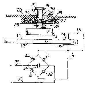
Figure 2 is an isolated side elevation view and schematic; electrical circuit
showing the
general construction of a preferred embodiment of the device of the present
invention.
When a crystal of high piezoelectricity such as barium titanate is subjected
to a force
applied on its appropriate axis a voltage is generated across the crystal.
This may be achieved as
shown in Figure 1, in which a high piezoelectric crystal 10 having a top
surface 11 and a bottom
surface 12. A force or impact may be exerted on the top surface 11 by a weight
13 so that a
voltage is generated between the top surface 11 and the bottom surface 12. Two
metal conductor
plates 14 and 15 are provided on the top surface 1 I and the bottom surface 12
respectively to
collect the generated voltage which may then be outputted through conductor
wires 16 and 17
connected to the conductor plates 14 and 1 S respectively.
The device of the present invention utilizes such phenomenon to generate the
electrical
power for operating an electronic unit. The device may be integrally
incorporated in the
electronic unit or alternatively it may be constructed in a separate enclosure
to which the

CA 02415301 2002-12-30
electronic unit is mounted. For simplicity of illustration, the following
embodiment shows the
device constructed in a separate enclosure to which the electronic unit may
then be mounted.
The high piezoelectric crystal block 10 is mounted within an enclosure having
a top
panel 18. A hammer weight 13 is mounted on a vertical shaft 19 which is
slidably mounted in an
opening 20 formed in the top panel 18 of the enclosure. A press button 21 is
provided at the top
end of the shaft 19. A tension coil spring 22 surrounding the shah 19 is
connected between the
hammer weight 13 and the panel 18. The coil spring 22 maintains the hammer
weight 13
normally spaced from the crystal block 10. The hammer weight 13 may be
operated to strike the
top surface 11 of the crystal block 10 by depressing the press button 21. In
order to ensure that a
0 consistent force is exerted on the top surface 11 by the hammer weight 13 a
latching mechanism
is provided. The latching mechanism includes a circumscribing circular groove
23 formed on
the shaft 19. The groove 23 normally engages with two round pressure balls 24
and 25 mounted
in two elongated closed end openings 26 and 27 respectively formed in two
opposite sides of the
side wall of the opening 20 of the top panel I7. The pressure balls 24 and 25
are pressed
transversely against the groove 23 by compression springs 28 and 29 located
respectively in the
elongated openings 26 and 27. The compression springs 28 and 29 have a high
spring force such
that the pressure balls 24 and 25 are pressed tightly against the groove 23 of
the shaft 19. Due to
the high pressure exerted on the groove 23 by the pressure balls 24 and 25 to
latch the shaft 19 in
the normal position, a relatively high force must be exerted on the press
button 21 in order to
unlatch the shaft 19 for moving the hammer weight 13 to contact the top
surface 11 of the crystal
block 10. This operation causes the shaft 19 to unlatch and move the hammer
weight 13 to strike
the top surface 11 of the crystal block 10 w=ith an impact force such that a
voltage is produced
-3-

CA 02415301 2002-12-30
between the top surface 11 and its bottom surface 12. When the pressure is
released from the
button 21, the tension spring force of the tension coil spring 22 will pull
the hammer weight 13
back to its original upper position with the groove 23 again engaging with the
pressure balls 24
and 25 to latch the shaft 19 in its normal upper position.
The voltage produced between the top surface 11 and the bottom surface 12 of
the crystal
block 10 is collected by the metal plates 14 and 15 and is conducted by wires
16 and 17 to pass
through a rectifier bridge circuit consisting of diodes 30, s l, 32, and 33 to
charge a capacitor 34.
T'he voltage across the terminals 35 and 36 of the fully charged capacitor 34
provides the
required power to operate the electronic unit.
It should be understood, of course, that the foregoing disclosure relates to
only a
preferred embodiment of the invention and that numerous modifications or
alterations may be
made therein without departing from the spirit and the scope of the invention
set forth in the
appended claims.
20
-4-

Representative Drawing
A single figure which represents the drawing illustrating the invention.
Administrative Status

2024-08-01:As part of the Next Generation Patents (NGP) transition, the Canadian Patents Database (CPD) now contains a more detailed Event History, which replicates the Event Log of our new back-office solution.

Please note that "Inactive:" events refers to events no longer in use in our new back-office solution.

For a clearer understanding of the status of the application/patent presented on this page, the site Disclaimer , as well as the definitions for Patent , Event History , Maintenance Fee  and Payment History  should be consulted.

Event History

Description Date
Inactive: IPC expired 2023-01-01
Revocation of Agent Requirements Determined Compliant 2021-04-01
Inactive: IPC from MCD 2006-03-12
Time Limit for Reversal Expired 2005-12-30
Application Not Reinstated by Deadline 2005-12-30
Deemed Abandoned - Failure to Respond to Maintenance Fee Notice 2004-12-30
Application Published (Open to Public Inspection) 2004-06-30
Inactive: Cover page published 2004-06-29
Inactive: First IPC assigned 2003-02-25
Application Received - Regular National 2003-02-10
Inactive: Filing certificate - No RFE (English) 2003-02-10

Abandonment History

Abandonment Date Reason Reinstatement Date
2004-12-30

Fee History

Fee Type Anniversary Year Due Date Paid Date
Application fee - small 2002-12-30
Owners on Record

Note: Records showing the ownership history in alphabetical order.

Current Owners on Record
REZA H. SHAH
Past Owners on Record
None
Past Owners that do not appear in the "Owners on Record" listing will appear in other documentation within the application.
Documents

To view selected files, please enter reCAPTCHA code :


To view images, click a link in the Document Description column. To download the documents, select one or more checkboxes in the first column and then click the "Download Selected in PDF format (Zip Archive)" or the "Download Selected as Single PDF" button.

List of published and non-published patent-specific documents on the CPD .

If you have any difficulty accessing content, you can call the Client Service Centre at 1-866-997-1936 or send them an e-mail at CIPO Client Service Centre.


Document
Description 
Date
(yyyy-mm-dd) 
Number of pages   Size of Image (KB) 
Description 2002-12-29 4 164
Abstract 2002-12-29 1 16
Claims 2002-12-29 2 57
Drawings 2002-12-29 1 17
Representative drawing 2003-03-19 1 11
Filing Certificate (English) 2003-02-09 1 159
Reminder of maintenance fee due 2004-08-30 1 110
Courtesy - Abandonment Letter (Maintenance Fee) 2005-02-23 1 174