Note: Descriptions are shown in the official language in which they were submitted.
CA 02415377 2002-12-24
FIELD OF THE INVENTION
The present invention relates to dispensing utensils that
can be manually manipulated to dislodge a substance therefrom, and
more particularly to a food-serving utensil such as a fork, spoon
or a knife that can be manually manipulated to dislodge a piece of
food therefrom.
BACKGROUND OF THE INVENTION
Dispensing utensils are used extensively in the serving
of buffet meals where guests pass along <~ food table laden with
food and take their requirements from serving plates as they pass
by. There is always a problem with some foods and some guests in
removing food selected by a guest for his plate from the fork or
spoon. The food in these particular situations just does not want
to leave the utensil. It is solved in many cases by fingering the
food off the food utensil. In other cases a vigorous shaking, of
the dispensing utensil will suffice. In still other cases
observant guests will not impale food on the fork or place food on
the end of the spoon very securely . This can result in dropped
food. In any event there is a problem and this invention overcomes
the problem.
CA 02415377 2002-12-24
There are also other situations where a utensil is used
to dispense a substance, such as scooping pet food into a dish.
The consistency of many types of pet foods is such that it sticks
the dispensing utensil, which makes it very difficult to dispense.
It is an object of this invention to provide a dispensing
utensil that can be simply and manually manipulated to dislodge a
substance off the dispensing utensil.
It is an object of this invention to provide a food-
serving utensil for food and the like that can be simply and
manually manipulated to dislodge food off the food-serving utensil.
It is a further object of this invention to provide such
a dispensing utensil that is inexpensive to manufacture.
SUN~SP~RY OF THE INVENTION
In accordance with one aspect of the present invention
there is disclosed a novel dispensing utensil comprising a body
extending between a front end and a back end, and having a handle
and a substance-holding end portion having a width and a lengthy a
substance pushing member for removing substance from the
- 2 -
CA 02415377 2002-12-24
substance-holding end portion of the body and, a resiliently
deformable arm having a front end and a back end, and connected
adjacent the front end to the substance pushing member and
connected adjacent the back end to the handle. The substance
pushing member is movable along the substance-holding end portion
between a rest position and a flexed dispensing position, and
wherein the distance between the rest position and the flexed
dispensing position comprises a substantial portion of the
substance-holding end portion.
In accordance with another aspect of the present
invention there is disclosed a novel dispensing utensil comprising
a body extending between. a front end and a back end, and having a
handle and a substance-holding end portion having a width and a
length; a substance pushing member for removing substance from the
substance-holding end portion of the body; and, an arm having a
front end and a back end, and connected adjacent the front end to
the substance pushing member and connected adj acent the back end to
the handle. The substance-holding end portion is sloped downwardly
to the front of the body, and the substance pushing member is
movable along the substance-holding end portion between a rest
position and a dispensing position, and wherein the distance
between the rest position and the dispensing position comprises a
substantial portion of the substance-holding end portion.
- 3 -
CA 02415377 2002-12-24
In accordance with yet another aspect of the present
invention there is disclosed a novel dispensing utensil comprising
a body extending between a front end and a back end, and having a
handle and a substance-holding end portion having a width and a
length; a substance pushing member for removing substance from the
substance-holding end portion of the body; and, an arm having a
front end and a back end, and connected adjacent the front end to
the substance pushing member and connected adj acent the back end to
the handle. The arm has a self-supporting upwardly bowed portion,
and the upwardly bowed portion presents a rear-facing thumb-
engaging portion, and wherein when the upwardly bowed portion is
pushed forwardly at the rear-facing thumb-engaging portion, the
substance pushing member is moved along the substance-holding end
portion from the rest position to -'the dispensing loosition.
In accordance with yet another aspect of the present
invention there is disclosed a novel dispensing utensil comprising
a body extending between a front end and a back end, and having a
handle and a substance-holding end portion having a width and a
length, a substance pushing member for removing substance from the
substance-holding end portion of the body;, and an arm having a
front end and a back end, and ccnnected adjacent the front end to
the substance pushing member and pivotally connected adjacent the
back end to the handle. The substance pushing member is movable
- 4 -
CA 02415377 2002-12-24
along the substance-holding end portion between a rest position and
a dispensing position, and wherein the distance between the rest
position and the dispensing position comprises a substantial
portion of the substance-holding end portion.
Other advantages, features and characteristics of the
present invention, as well as methods of operation and functions of
the related elements of the structure, and the combination of parts
and economies of manufacture, will become more apparent upon
consideration of the following detailed description and the
appended claims with reference to the accompanying drawings, the
latter of which is briefly described herein below.
BRIEF DESCRIPTION OF THIS DRAWINGS
The ncvel features which Gre believed to be
characteristic of the dispensing utensil according to the present
invention, as to its structure, organization, use and method of
operation, together with further objectives and advantages thereof,
will be better understood from the following drawings in which a
presently preferred embodiment of the invention will now be
illustrated by way of example. It is expressly understood,
however, that the drawings are for the purpose of illustration and
- 5 -
CA 02415377 2002-12-24
description only, and are not intended as a definition of the
limits of the invention. In the accompanying drawings:
Figure 1 is a perspective view of a first preferred
embodiment of the dispensing utensil according to the present
invention;
Figures 2, 3, 4 and 5 are line illustrations of the
operation of the dispensing utensil of Figure 1;
Figure 6 is a perspective view of second preferred
embodiment of the dispensing utensil according to the present
invention;
Figure 7 is a perspective view of a third preferred
embodiment of the dispensing utensil according to the present
invention;
Figure 8 is a perspective view of a fourth preferred
embodiment of the dispensing utensil according to the present
invention;
- 6 -
CA 02415377 2002-12-24
Figure 9 is a perspective view of a fifth preferred
embodiment of the dispensing utensil according to the present
invention;
Figure 10 is a perspective view of a sixth preferred
embodiment of the dispensing utensil according to the present
invention;
Figure 11 is a side elevational view of the dispensing
utensil of Figure 10;
Figure 12 is a perspective view of a seventh preferred
embodiment of the dispensing utensil according to the present
invention;
Figure 13 is a top plan view of the dispensing utensil of
Figure 12;
Figure 14 is a side elevational view of the dispensing
utensil of Figure 12;
Figure 15 is a perspective view of a eighth preferred
embodiment of the dispensing utensil according to the present
invention;
CA 02415377 2002-12-24
Figure 16 is a perspective view of a ninth preferred
embodiment of the dispensing utensil according to the present
invention;
Figure 17 is a top plan view of the dispensing utensil of
Figure 16;
Figure 18 is a top plan view similar to Figure 17 but
with a portion of the dispensing utensil moving with respect to
another portion of the dispensing utensil;
Figure 19 is a side elevational view of the dispensing
utensil of Figure 16;
Figure 20 is a perspective view of a tenth preferred
embodiment of the dispensing utensil according to the present
invention;
Figure 21 is a side elevational ~;riew of the dispensing
utensil of Figure 20;
Figure 22 is a top plan view of the dispensing utensil of
Figure 20;
_ g _
CA 02415377 2002-12-24
Figure 23 is an end elevational view of the dispensing
utensil of Figure 20;
Figure 24 is a perspective view of an eleventh preferred
embodiment of the dispensing utensil according to the present
invention;
Figure 25 is a perspective view of a twelfth preferred
embodiment of the dispensing utensil according to the present
invention;
Figure 26 is a perspective view of a thirteenth preferred
embodiment of the dispensing utensil according to the present
invention;
Figure 27 is a perspective view of a fourteenth preferred
embodiment of the dispensing utensil according to the present
invention;
Figure 28 is a top plan view of the dispensing utensil of
Figure 27;
Figure 29 is a side elevational view of the dispensing
utensil of Figure 27;
- 9 -
CA 02415377 2002-12-24
Figure 30 is a perspective view of a fifteenth preferred
embodiment of the dispensing utensil according to the present
invention;
Figure 33. is a perspective view of a sixteenth preferred
embodiment of the dispensing utensil according to the present
invention;
Figure 32 is a perspective view of a seventeenth
preferred embodiment of the dispensing utensil according to the
present invention;
Figure 33 is a top plan view of the dispensing utensil of
Figure 32;
Figure 34 is a perspective view of a eighteenth preferred
embodiment of the dispensing utensil according to the present
invention;
Figure 35 is a perspective view of a nineteenth preferred
embodiment of the dispensing utensil according to the present
invention;
- 10 -
CA 02415377 2002-12-24
Figure 36 is a perspective view of a twentieth preferred
embodiment of the dispensing utensil according to the present
invention;
Figure 37 is a perspective view of a twenty-first
preferred embodiment of the dispensing utensil according to the
present invention;
Figure 38 is a perspective view of a twenty-second
preferred embodiment of the dispensing utensil according to the
present invention;
Figure 39 is a perspective view of a twenty-third
preferred embodiment of the dispensing utensil according to the
present invention;
Figure 40 is a perspective view of a first portion of the
twenty-third preferred embodiment of the dispensing utensil shown
in Figure 39;
Figure 41 is a perspective view of a second portion of
the twenty-third preferred embodiment of the dispensing utensil
shown in Figure 39;
- 11 -
CA 02415377 2002-12-24
Figure 42 is a front perspective view of a twenty-fourth
preferred embodiment of the dispensing utensil according to the
present invention, with the substance pushing member in its rest
position;
Figure 43 is a front perspective view similar to Figure
42, but with the substance pushing member in its flexed dispensing
position;
Figure 44 is a rear perspective view of the dispensing
utensil as shown in Figure 43;
Figure 45 is a top plan view of the dispensing utensil as
shown in Figure 43;
Figure 46 is a side elevational view of a twenty-fifth
preferred embodiment of the dispensing utensil according to the
present invention, with the substance pushing member in its rest
position; and,
Figure 47 is a side elevational view similar to Figure
47, but with the substance pushing member in its dispensing
position.
- 12 -
CA 02415377 2002-12-24
DETAILED DESCRIPTION OF 1~ PREFERRED EMBOD7:MENT
Referring to Figures 1 through 47 of the drawings, it
will be noted that Figures 1 through 5 illustrate a first preferred
embodiment of the dispensing utensil of the present invention,
F;~gure 6 illustrates a second preferred embodiment of the
dispensing utensil of the present inventic>n, Figure 7 illustrates
a third preferred embodiment of the dispensing utensil of the
present invention, Figure 8 illustrates a fourth preferred
embodiment of the dispensing utensil of the present invention,
Figure 9 illustrates a fifth preferred embodiment of the dispensing
utensil of the present invention, Figures 10 and 11 illustrate a
sixth preferred embodiment of the dispensing utensil of the present
invention, Figures 12 through 14 illustrate a seventh preferred
embodiment of the dispensing utensil of the present invention,
Figure 15 illustrates a eighth preferz°ed embodiment of the
dispensing utensil of the present invention, Figures 16 through 19
illustrate a ninth preferred embod~.ment of the dispensing utensil
of the present invention, Figures 20 through 23 illustrate a tenth
preferred embodiment of the dispensing utensil of the present
invention, Figure 24 illustrates a eleventh preferred embodiment of
the dispensing utensil of the present invention, Figure 25
illustrates a twelfth preferred embodiment of the dispensing
utensil of the present invention, Figure 26 illustrates a
- 13 -
CA 02415377 2002-12-24
thirteenth preferred embodiment of the dispensing utensil of the
present invention, Figures 27 through 29 illustrates a fourteenth
preferred embodiment of the dispensing utensil of the present
invention, Figure 30 illustrates a fifteenth preferred embodiment
of the dispensing utensil of the present invention, Figure 31
illustrates a sixteenth preferred embodiment of the dispensing
utensil of the present invention, Figures 32 and 33 illustrate a
seventeenth preferred embodiment of the dispensing utensil of the
present invention, Figure 34 illustrates a eighteenth preferred
embodiment of the dispensing utensil of the present invention,
Figure 35 illustrates a nineteenth preferred embodiment of the
dispensing utensil of the present :invention, Figure 36 illustrates
a twentieth preferred embodiment of the dispensing utensil of the
present invention, Figure 3'7 illustrates a. twenty-first preferred
embodiment of the dispensing utensil of the present invention,
Figure 38 illustrates a twenty-second preferred embodiment of the
dispensing utensil of the present invention, Figures 39 through 41
illustrate a twenty-third preferred embodiment of the dispensing
utensil of the present invention, Figures 42 through 45 illustrate
a twenty-fourth preferred embodiment of the dispensing utensil of
the present invention, and Figures 46 and 47 illustrate a twenty-
fifth preferred embodiment of the dispensing utensil of the present
invention.
- 14 -
CA 02415377 2002-12-24
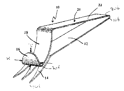
Reference wil=L now be made to Figures 1 through 5, which
show a first preferred embodiment of the d_~spensing utensil of the
present invention, as indicated by general reference numeral 8.
The dispensing utensil 8 is in the form of a fork and comprises a
body 10 extending between a front end 10f and a back end 10b. A
substantially rigid handle 12 has a substance-holding pronged end
portion 14 for holding food. The substance-holding end portion has
a width "W" and a length "L°', and is sloped downwardly to the front
lOf of the body 10. A substance pushing :member in the form of a
scraper 16 is formed at the curved outer part 18 of the arm,
generally referred to by the numeral 20. The substance pushing
member is for removing substance from the substance-holding end
portion 16 of the body 10. The arm 20 is resiliently deformable
and has a front 20f end and a back end 20b. As can be seen in the
Figures, the resiliently deformable arm 20 is connected adjacent
its front end 20f, and preferably at the front end 20f, to the
substance pushing member 16. Fu=ether, the arm 20 is connected
adjacent its back end 20f, and preferably at its back end 20f, to
the handle 12. As illustrated, the arm 20 has a straight section
22 that joins with the handle 12 of the body 10.
As can be seen in Figures 2, 3, 4 and 5, which are line
drawings illustrating the flexing and scraping action of the
dispensing utensil 8. The substance pushing member 16 is movable
_ 15 _
CA 02415377 2002-12-24
along the substance-holding end portion 14 between a rest position,
as shown in Figure 2, and a flexed dispensing position. Various
flexed dispensing positions are shown in Figures 3 through 5.
Figure 3 shows a flexed dispensing position wherein the substance
pushing member 16 has moved just past half way along the substance-
holding end portion 14, as indicated by arrow °'A", through downward
f,_exion of the resiliently deformable arm 20, as indicated by arrow
"B". In this position, in many instances, at least a substantial
portion of the substance on the substance-holding end portion 14
would be dispensed. Figure 4 shows a flexed dispensing position
where the substance pushing member 16 has moT,red almost all of the
way along the substance-holding end portion 14, as indicated by
arrow "C", through downward flexion of the resiliently deformable
arm 20, as indicated by arrow "D". In thi:> position, Virtually of
the substance on the substance-holding end portion 14 would be
dispensed, except possibly in some cases. Figure 5 shows the
substance pushing member 16 having moved entirely to the front end
20f of the substance-holding end portion 14, as indicated by arrow
"E", through downward flexion of the resiliently deformable arm 20,
as indicated by arrow "F". In this flexed dispensing position,
essentially all of the substance on the substance-holding end
portion 14 would be dispensed, even if it was solid item, such as
perhaps a pickle, impaled by the substance-holding end portion 14.
- 16 -
CA 02415377 2002-12-24
As can be seen in Figures 2 through 5, the distance
between the rest position and the various flexed dispensing
positions comprises of substantial portion of the substance-holding
end portion 14. The substance pushing member 16 is movable along
the length "L" of the substance-holding end portion 14.
The dispensing utensil 8 is preferably made of suitable
resilient flexible material such as stainless spring steel, but
other resilient compositions such as commerically available
moldable materials or plastics material, o.r other resilient metals
can also be used. The dispensing utensil 8 is preferably formed
from a single unitary piece of metal or plastic. Alternatively,
the dispensing utensil_ 8 may be formed from both plastic and metal.
The area of greatest arm flex will be at the bend 24 of the scraper
arm 20. It will be noted that the scraper arm 20 is resilient and
bowed in a direction away from the handle and, in use, as the bowed
and resilient scraper arm is manually pressed towards the handle,
the end of the scraper arm bears against and outwardly of the
pronged end of the fork and causes the scraper 16 to move outwardly
of the pronged end to push off any food that may be impaled on the
fork. This action is illustrated in Figures 2, 3, 4 and 5.
The embodiment is capable of variation in form without
departing from the spirit of the present invention. For example the
- 17 -
CA 02415377 2002-12-24
upturned scraper 16 could be replaced by the simple forward edge of
the curved section 18 of the scraper arm 20. Such an embodiment is
illustrated in Figure 6. In Figure 6, there is a bowed scraper arm
26 with a scraper edge 28 at the free end thereof for slideable
engagement with the pronged end portion 32 of the handle 34. The
operation of this embodiment is similar t:o the operation of the
embodiment shown in Figures 1 to 5. As the bowed handle is flexed
to carry it toward the handle 34, the scraper edge 28 is pushed
outwardly along the pronged end portion 32 to force food off of the
fork.
Figure 7 illustrates a still further embodiment, namely
that of a spoon, which has a body generally referred to by the
numeral 39. The body is formed with a handle 44 and a dished
receptable end portion 46 for holding food. A scraper 48, which
comprises a dish-shaped member, is formed <~t the curved outer part
of the arm, generally referred to by the numeral 52. The arm 52
has a straight section 54 that joins with the handle 44 of the body
39 at 42. The resiliently deformable arm 52 has an upwardly bowed
portion that extends most of the length of the arm 52. In
operation, as the bowed scraper arm 52 is manually pressed towards
the handle 44, the dish-shaped scraper 48 on the free end of the
scrapper arm 52 moves outwardly to slide the scraper 48 along the
-- 18 _
CA 02415377 2002-12-24
concaved surface of the dished receptacle end portion 46 to clear
any food or the like of.f of the spoon.
Figure 8 is a fourth prefer=red embodiment of the
dispensing utensil of the present invention and a further
embodiment of a spoon. In Figure 8, there is a bowed scraper arm
60 with a scraper edge 62 at the free end thereof for slideable
engagement with the dished receptacle portion 64 of the handle 66.
Again, the operation of this embodiment is similar to the operation
of the embodiment shown in Figures 1 to 5. As the bowed handle 60
is flexed to carry it toward the handle 66, the scraper edge 62 is
pushed outwardly along the dished receptacle portion 64 to scoop
food off of the spoor..
Figure 9 is a fifth preferz°ed embodiment of the
dispensing utensil 500 of the present invention, and is similar to
Figure 8, except that it is a "spork", which is a combination of a
spoon and a fork.
A sixth preferred embodiment of the dispensing utensil
600 of the present invention is mown in Figures 10 and 11. The
substance holding portion 602 is more of a slightly curved blade,
essentially of a cross between a spoon and a knife, and the scraper
604 is small in height and has a concave front surface 606.
- 19 -
CA 02415377 2002-12-24
The seventh preferred embodiment of the dispensing
utensil 700 is shown in Figures 12 through 14, and has an extended
handle 702 and an arm 703 having an inverted ~~v-shaped°' upwardly
bowed portion 704. The rear portion 706 of the inverted '~v-shaped"
upwardly bowed portion 704 presents a rear-facing thumb-engaging
portion 706 that is widened to accommodate receiving a person's
thumb. When the upwardly bowed portion 704 is pushed forwardly at
the rear-facing thumb-engaging portion 706, the substance pushing
member 708 is moved along the substance-holding end portion 710
from its rest position to its flexed dispensing position. The arm
703 further comprises a low profile portion 712 disposed rearwardly
of the upwardly bowed portion 704 and disposed in close relation to
the handle 702, S.aith perhaps about one-quarter inch between the low
profile portion 712 and the handle 702. The bowed profile portion
712 and the handle 702 together form a readily graspable portion,
which permits ready engagement of the rear-facing thumb-engaging
portion 706 by a user's thumb.
An eighth embodiment of the dispensing utensil 800 is
shown in Figure 15, which is similar to Figure 6, except that the
dispensing utensil 800 is made from two pieces of material, a first
piece of material 802 and a second piece of material 804, each
being either plastic or metal, secured together by a fastener 806,
such as a rivet or machine screw.
- 20 -
CA 02415377 2002-12-24
A ninth preferred embodiment of the dispensing utensil
900 of the present invention is shown in Figures 16 through 19.
The dispensing utensil 900 has a scraper blade 902 that is oriented
substantially perpendicularly to the substance-holding end portion
904, and moves laterally across the substance holding portion 904
as indicated by arrow 18a in Figure 18 so as to be movable across
the width of the substance-holding end portion 904. There is also
an enlarged thumb-engaging portion 906.
A tenth preferred embodiment of the dispensing utensil
1000 of the present invention is shown in Figures 20 through 23.
The dispensing utensil ~!000 has a substance holding portion in the
form of a gathering blade 1002, essentially a knife, and a scraper
blade 1004 that is moved downwardly so as to scrape laterally
across the gathering blade, as indicated by arrows 21a in Figure 21
and 23a in Figure 23. The bottom edge 1006 of the scraper blade
1004 may be slightly concaved and form a sharp inner edge 1008 that
scrapes against the gathering blade 1002, as can be best seen in
Figure 23.
Reference will now be made to Figure 24, which shows an
eleventh preferred embodiment of the dispensing utensil 1100 of the
present invention. The dispensing utensil 1100 has a single fork
tine 1102 that is used to impale objects, such as pickles. The
- 21 -
CA 02415377 2002-12-24
pusher blade 1104 moves along the single tine 1102 to push the
pickle off the tine, in a manner similar to that illustrated for
removing food as shown in Figures 2 through 5 of the first
preferred embodiment of the dispensing utensil of the present
invention.
A twelfth preferred embodiment of the dispensing utensil
1200 of the present invention, as shown in Figure 25, is similar to
that shown in Figure 24, except that it has a plurality of tines
1202 and the pusher blade 1204 is correspondingly wide so as to
extend across the plurality of tines 1202.
A thirteenth preferred embodiment of the dispensing
utensil 1300 of the present invention is shown in Figure 26, which
dispensing utensil is similar to that shown in Figures 20 through
23, except that the gathering blade 1302 (substance holding end
portion} is rounded and serrated.
A fourteenth preferred embodiment of the dispensing
utensil 1400 of the present invention is shown in Figures 27
through 29. The scraper blade 1402 is connected to the body
portion 1404 of the handle 1406 by an upwardly bowed portion 1408.
Further, the scraper blade 1402 has an inverted "L-shaped" cross-
- 22 -
CA 02415377 2002-12-24
section to help scrape substances off the scraper blade 1402 (the
substance holding end portion) of the dispensing utensil 1400.
A fifteenth preferred embodiment of the dispensing
utensil 1500 of the present invention is ;shown in Figure 30. The
substance holding end portion 1502 has concave from front to back,
but is shaped straight laterally to permit ready scraping by the
scraper blade 1504 that is curved to match the concave shape of the
substance holding end portion 1502. The scraper blade 1504 is
removably connected to the body portion 1506 of the dispensing
utensil 1500 by a laterally bowed portion 1508 that terminates in
an end loop 1510, with the aperture 1512 of the loop 1510 receiving
the handle 1514 of the dispensing utensil 1500.
A sixteenth preferred embodiment of the dispensing
utensil 1600 of the present invention is shown in Figure 31, and is
similar to the fifteenth preferred embodiment of the dispensing
utensil of the present invention is shown in Figure 30, except that
the scraper blade 1602 is integrally connected to the body portion
1604 of the dispensing utensil 1600 by a laterally bowed portion
1606.
A seventeenth preferred embodiment of the dispensing
utensil 1700 of the present invention is shown in Figures 32 and
- 23 --
CA 02415377 2002-12-24
33, and is similar to the seventh preferred embodiment is shown in
Figures 12 through 14, except that the inverted "v-shaped" portion
1702 terminates near the forward portion 1704 of the handle 1706,
and the substance scraping portion 1708 is wide so as to cover most
of the width of the "spork". The rear portion 1710 of the inverted
"v-shaped" portion 1702 is widened to accommodate receiving a
person°s thumb.
An eighteenth preferred embodiment of the dispensing
utensil 1800 of the present invention is shown in Figure 34, and is
similar to the seventeenth preferred embodiment is shown in Figures
32 and 33, except that the forward portion 1802 of the handle
portion 1804 is more gently curved.
A nineteenth preferred embodiment of the dispensing
utensil 1900 of the present invention is shown in Figure 35, and is
similar to the eighteenth preferred embodiment is shown in Figure
34, except that the inverted "v-shaped" portion 1902 is actually a
curved shape and does not have a widened portion.
A twentieth preferred embodiment of the dispensing
utensil 2000 of the present invention is shown in Figure 36, and is
similar to the sixth preferred embodiment is shown in Figures 10
and 11, except that the dispensing utensil 2000 is a fork.
- 24 -
CA 02415377 2002-12-24
A twenty-first preferred embodiment of the dispensing
utensil 2100 of the present invention is shown in Figure 37, and is
similar to the twentieth preferred embodiment of the dispensing
utensil of the present invention is shown in Figure 36, except that
the dispensing utensil 2100 is a "spork", and the downwardly turned
end portion 2102 of the scraper 2104 is smaller.
A twenty-second preferred embodiment of the dispensing
utensil 2200 of the present invention is shown in Figure 38, and is
similar to the twenty-first preferred embodiment of the dispensing
utensil of the present invention is shown in Figure 37, except that
the end portion 2202 of the scraper 2204 is upwardly turned and
larger.
A twenty-third preferred embodiment of the dispensing
utensil 2300 of the present invention is shown in Figures 39
through 41, and comprises a first portion 2301 (shown separately in
Figure 40) and a second portion 2302 (shown separately in Figure
41). The first portion 2301 is in the form of a spoon (although
other forms such as a fork, "spork'°, or the like would also work)
and includes a handle portion 2304 attached to a substance-holding
end portion 2306. The second portion 2302 includes a scraper arm
2308, with one end of the scraper arm 2308 connecting with a
scraper 2310 and the other end of the scraper arm 2308 having a
- 2~ -
CA 02415377 2002-12-24
"C'°-shaped mounting portion 2312 that permits the second portion
2302 to be removably connected to the handle portion 2304 at a co-
operating reduced portion 2314. It is also contemplated that the
second portion 2302, or an element similar to it, could be mounted
onto a conventional spoon, fork, "spork", or the like, a.nd be used
in an analogous manner as described herein.
A twenty-fourth preferred embodiment of the dispensing
utensil 2400 of the present invention is shown in figures 42
through 45. The dispensing utensil 2400 comprises a body 2402
extending between a front end 2402f and a back end 2402b. The body
2402 has a handle 2404 and a substance-holding end portion 2406
having a width "GJ" and a length "L". A substance pushing member
2408 in the form of a scraper is used for removing substance from
the substance-holding end portion 2406 of the body 2402.
An arm 2410 has a front end 2410f and a back end 2410b.
The arm 2410 is connected adjacent the front end 2410f to the
substance pushing member 2408 and is pivotally connected adjacent
the back end 2410b to the handle 2404 by means of co-axial pins
2412 pivotally disposed in co-operating orifices 2414 in the handle
2404.
- 26 -
CA 02415377 2002-12-24
The substance pus:ning member 2408 is movable along the
substance-holding end portion 2406 between a rest position, as
shown in Figure 46, and a dispensing position, as shown in Figure
47. The distance between the rest position and the dispensing
position comprises a substantial portion of the substance-holding
end portion 2406.
The resiliently deformable arm has an upwardly bowed
portion 2416 that presents a rear-facing thumb-engaging portion
2418. When the upwardly bowed portion 2416 is pushed forwardly at
the rear-facing thumb-engaging portion 2418, the substance pushing
member 2408 is moved along the substance-holding end portion 2406
from the rest position to the flexed dispensing position,
A twenty-fifth preferred embodiment of the dispensing
utensil 2500 of the present invention is shown in Figures 46 and
47. The dispensing utensil 2500 is similar to first preferred
embodiment dispensing utensil 8, for instance, except that the
resiliently deformable arm 2502 is bowed downwardly under the
handle 2504 and extends upwardly around the substance holding end
portion 2506, to terminate in a substance pushing member 2508 above
the substance holding end portion 2506. Alternatively, the arm
2502 could pass through a slot (not shown) in the substance holding
end portion 2506. In use, squeezing together the resiliently
- 27 -
CA 02415377 2002-12-24
deformable arm 2502 and the handle 2504, as indicated by arrow "G",
causes the substance pushing member 2508 to move along the upwardly
slanted substance holding end portion 2506 thereby dispensing
substance therefrom.
From the foregoing it will be apparent that the invention
achieves its objective of providing a simple efficient rugged and
inexpensive dispensing utensil that permits ready dispensing of
substances, such as food, carried thereon, with an easy operation
of the hand in a sanitary manner. It fulfils a longstanding want
fcr such a device, especially in the serving of buffet style meals,
bulk food dispensing situations and barbeque condiment settings.
As can be understood from the above description and from the
accompanying drawings, the present invention provides a dispensing
utensil which is not found in the prior art.
Other variations of the above principles will be apparent
to those who are knowledgeable in the field of the invention, and
such variations are considered to be within the scope of the
present invention. Further, other modifications and alterations
may be used in the design and manufacture of the dispensing of the
present invention without departing from the spirit and scope of
the accompanying claims.
_ 2g __