Note: Descriptions are shown in the official language in which they were submitted.
CA 02415410 2003-O1-06
Certified Translation from German into English
[Letterhead of Eisenfuhr, Speiser & Partner, Patent Attorneys]
1 ..
Bremen, 9 July 2001 ~ 'IIM SPE~tE
Sthlochte 3'S
Our ref,: W 2421 KGG/SAS/cmu
ApplicantlProprietor: WOBBEN, Aloys ~~ 28i9~~~ y ,
Official file no.: New application ''o"p
6e 'edgerichtsb
~B~'e~ der rn9~V~
Aloys Wobben, Argestral3e 19, 26607 Aurich
Apparatus for handling unit loads
The present invention relates to a device for gripping a unit load during
handling of
same, said device comprising an attachment portion for attaching the device to
the
unit load and a gripping portion for gripping a handling means.
Standardized containers have long been used to great advantage for the
transportation of goods. At their corners, these containers have facilities,
referred to
as container corners or twist blocks, that project beyond the sides of the
container
therebetween by a certain amount. Said container corners are designed in such
a way
that standardized holders can engage with and be locked into said container
corners.
Goods of large volume (referred to hereinafter as unit loads) cause
substantial
problems during handling or transportation when they are unsuitable for
CA 02415410 2003-O1-06
-2-
containerized transport, for example on account of their dimensions andlor
weight.
Such unit loads can be steel towers or tower segments, for example, which must
often
- be transported as supports for telecommunications facilities or wind
turbines. Such
sections are usually 11 - 25 metres in length, up to 4 metres in diameter and
between
20 - 70 tonnes in weight. These figures may even be exceeded.
In the following, the invention and the problems encountered in the prior art
are
described with reference to such steel tower segments. However, attention is
expressly drawn to the fact that the invention is not confined to such
applications and
that it essentially relates to any kind of unit load.
As is well known, steel tower sections present a series of handling and
transportation
tasks, beginning with manufacture and continuing through transportation to the
construction site and to erection of the edifice.
Both ends of the mostly circular cylindrical tower segments are usually fitted
with
flanges with which the separate sections are connected during erection. Said
flanges
are also used in most cases to attach the handling or transportation means to
the
section.
Such means are rotary adapters, for example, by means of which the sections
horizontally aligned along their longitudinal axis can be turned about their
longitudinal
axis, in order, for example, to perform paint finishing work at any part of
the outer wall.
These rotary adapaters are fastened with screws to the flanges.
By this method, for example, feet are screwed onto the flanges to enable the
section to
be stored with a predetermined clearance from the ground. As soon as the feet
are
attached and the section has been laid down, the rotary adapters are removed.
The
feet are positioned in such a way that there is a certain probability that
they still fit and
do not have to be refitted when the section is later transported by truck.
When the sections are smaller, they can be transported by truck on a low
loader.
CA 02415410 2003-O1-06
-3-
However, a so-called boiler bridge is required in the case of larger sections.
Such a
boiler bridge comprises a traction unit with a low loader mounted thereto and
a rear
trailer, said low loader and trailer being connected to each other by spars
and the gap
between the two being adjustable within certain limits. When a section is
transported
using the boiler bridge, on the other hand, different feet must be screwed
onto the
section in order to hold it in a certain position on the spars of the boiler
bridge.
As soon as the section reaches the construction site, hoisting brackets are
screw-
fastened to the flange of the segment that is to be set upright for assembly.
As soon
as the section has been raised using the hoisting brackets, the feet are
removed from
the flange, and the section can be fitted into the tower.
If part of the transportation route is by sea, the feet attached to the
section can be
welded to the deck of the ship. The feet have to be changed again if the
section was
transported to the port using a boiler bridge. Although welding the feet is
both a simple
and effective way of securing the section for transportation, it harbours the
risk of the
section being damaged when the cargo is discharged - especially when the feet
are
not separated from the deck of the ship, but simply screwed off the flanges of
the
section instead. What is more, the feet that are then missing or destroyed
have to be
replaced by new ones in order to transport the section by truck from the port
to the
construction site.
As an alternative to welding the feet to the deck of the ship, the sections
are secured
by chains, for example, which are fed either through the holes in the section
or around
the outside of the section and then made fast. In order to hold the heavy
section in a
reliable way, the chains are tightly lashed. This can easily lead to
deformations in the
' section, or damage to the coating, for example. If a boiler bridge is ready
for use in the
destination port, it is necessary to change the feet once again.
Notorious devices are integral elements with two portions, one of which is for
fastening
the device to the unit load and the other for operation during handling (e.g.
hoisting or
laying down).
CA 02415410 2003-O1-06
-4-
In the devices described, the frequent, time-consuming and hence cost-
intensive
refittings for the various carrying, support and hoisting procedures during
handling of
the section in the manufacturing process and during transportation are severe
disadvantages. Each device is essentially designed for one task only and for
one
function only.
One transportation variant on land is a so-called transportation cross. The
latter
comprises a traction unit and a trailer. The linkage between the two vehicles
is
provided by the item to be transported - i.e. the tower section, for example.
Holding
devices that can be screwed to the flanges of the section are disposed on the
traction
unit and on the trailer.
Assembly and disassembly of the section between the traction unit and the
trailer
takes a disadvantageous 2.5 to 3 hours in each case, during which time the
section
must be held by a crane. Use of both the crane and the personnel required is
therefore
blocked for a very long time.
The object of the present invention is therefore to provide universally
deployable
handling means for unit loads, in particular for the production,
transportation and
assembly of such unit loads.
This object is achieved by the invention with a device as set forth in claim
1, with a
set of devices as set forth in claim 7, or with a transport vehicle pursuant
to claim 21.
Preferred embodiments of the invention are described in the subclaims.
- According to the invention, a gripping portion of a gripping device for a
unit load is
embodied in the form of a container corner, that is to say a standard
container
bracket. Given that such container corners are the standardized interfaces for
hoisting
and handling containers, and a substantial portion of all military and
commercial
logistics worldwide is effected with containers, all the relevant and
requisite handling
and transportation facilities are available worldwide in order to handle and
transport
CA 02415410 2003-O1-06
-5-
unit loads fitted with such appliances.
- In one preferred embodiment of the invention, an attachment portion of the
gripping
device pursuant to the invention has attachment facilities that are designed
to match
the unit loads to which the device is to be attached. If the unit load has
attachment
holes in a flange, for example, then the attachment portion may also have
attachment
facilities, e.g. in the form of through holes with identical spacing to those
on the
flange. It is therefore possible to attach the device securely to the unit
load in a fast
and uncomplicated manner.
In another preferred embodiment, the gripping device according to the
invention has
a indentation that is provided with plate-shaped elements. These are
preferably
arranged at right angles to each other (and preferably vertical to the the
plate-shaped
base member of the gripping device), such that the indentation is confined on
two
sides by said plate-shaped elements and is shaped as an indentation. To
transport the
unit load using a boiler bridge, the unit load can be supported on the spars
of the
boiler bridge by means of these indentations fitted with plates, in that the
indentations
conform to the shape of the - otherwise parallel - spars and cradle them. In
the case
of spars with lying rectangular cross-section, for example, the plates are
oriented in
such a way that one lies horizontally on one spar and the respective other
plates lies
across opposite sides of the spar for laterally securing the unit load.
In a preferred configuration of the invention, the gripping portion is spaced
at a
distance from the attachment facilities, and in the attachment device area at
least one
additional attachment facility is provided to which additional cross-members,
for
example, can be attached within the boundaries of the unit load if the grip
device
' according to the invention is accordingly fitted.
Eyes can also be provided on the grip device according to the invention, to
which
tarpaulins, for example, can be attached in order to cover the unit load.
According to the invention, an adapter for receiving a unit load is also
provided, said
CA 02415410 2003-O1-06
-6-
adapter comprising a support to andlor in which connector elements are
disposed
that can be connected to the gripping portion of the appliances according to
the
invention, which take the form of container corners. This makes it possible,
in the
case of very heavy unit loads, to distribute the weight over a larger surface
via a
support, in that the support has a level supporting surface, for example.
In one preferred embodiment, the adapter has four connector elements that are
disposed alongside each other on the support, preferably in the form of a
straight
beam, and of which at least two have a certain spacing between each other. If
the
spacing between said connector elements according to the invention is equal to
that
of a standardized container dimension, said two fixedly spaced connector
elements
permit the adapter to be attached in standardized holders, such as those
found, for
example, on container trucks or on the container decks of ships.
The remaining connector elements may be set or even adjusted to a spacing that
- permit unit loads to be fastened, by means of gripping devices according to
the
invention, with a different spacing to that between the standardized holders.
If the
outer connector elements have the standard spacing, the inner connector
elements
can hold a unit load with gripping devices with a smaller spacing between them
than
the standard spacing. If the inner connector elements have a standard spacing
between them, then the outer connector elements hold the unit load, which is
fitted
with devices that have a greater spacing between them than the standard
spacing.
Alternatively, all connector elements can have predefined spacings between
them,
such that the adapter matches certain unit loads, or unit loads with certain
dimensions,
and can be used immediately without adaptation being necessary.
The invention also relates to a transport means with a towing vehicle and a
trailer,
wherein the towing vehicle and trailer are connected during transportation by
the unit
load, and the towing vehicle and trailer have devices at the ends facing each
other
for holding the unit load.
CA 02415410 2003-O1-06
The transport means is preferably so configured that the holding devices have
certain
connector elements, so-called container brackets, at which the unit load can
be quickly
- and easily fastened to the transport means with the gripping devices
according to the
invention that are attached to the unit load.
The transport means can have fixed, predefined spacings between the container
brackets, or the holding devices can be adjustable in their height andlor
their width.
The container brackets are then attached to the adjustable portions of the
holding
devices. The holding devices are preferably adjusted by hydraulic means, in
particular,
such that they can be easily adjusted to the dimensions of the item to be
transported.
The transport vehicle for a unit load, comprising a towing vehicle and a
trailer,
preferably has matching connector elements at the ends of said towing vehicle
and
trailer that face each other. Said matching connecting elements are arranged
relative
to each other in such a way that the towing vehicle and the trailer can be
directly
connected to each other. Thus, if the transport vehicle is not loaded with a
unit load
(and hence there is no unit load to join the towing vehicle and the trailer),
the towing
vehicle and the trailer are connected by the connector elements according to
the
invention in such a way that the resultant entity can be driven. In this way,
a drivable
entity with the shortest possible length can advantageously be formed in
accordance
with the invention, said entity being easy to manoeuvre like a single vehicle
on account
of the substantially rigid link between the towing vehicle and the trailer -
and not
difficult to manoeuvre like the traction unit with the trailer connected by
the tow-bar,
as in the prior art.
The connector elements can have spars oriented horizontally in the direction
of travel,
said spars being lying one above the other in order to connect the towing
vehicle and
' the trailer, with preferably level flange surfaces that may, for example, be
horizontal.
To secure the connection, the connector elements may have bolts that engage
with
matching holes on the other side with clearance fit. Such connector elements
with
matching fit are preferred according to the invention, because they can be
connected
together in a particularly fast manner. Furthermore, an essentially rigid
connection
between the traction unit and the trailer can then be achieved preferably by
means of
CA 02415410 2003-10-24
-
clamping elements such as simple ratchet tighteners or bracing belts or
threaded
tension jacks attachable between the towing vehicle and the trailer, for
example to
lugs, and which can clamp the traction unit and the trailer to each other also
in such a
way that the interlocking connection in the example is secured against
loosening.
Yet other advantageous embodiments of the invention are described in the
following
with reference to the attached figures. These show: _
Fig. 1 a a three-dimensional view of a gripping device according to the
invention;
Fig. 1a-b front view and side elevation, view of an alternative embodiment of
a
gripping device according to the invention;
Fig. 1 c-a front view and side elevation view of another alternative
embodiment of a
gripping device according to the invention;
Fig. 2 a three-dimensional view of another alternative gripping device
according
to the invention;
Fig. 3 a plan view of an adapter according to the invention;
Fig. 4 a front view of a set of gripping devices according to the invention,
with
the adapter of the invention attached to two tower segments as
transportation load;
Fig. 5 two side elevation views of a transport vehicle according to the
invention,
with and without transportation load;
Fig. 6 a rear view of a holding device of the transport vehicle as defined by
the
invention;
Fig. 7 a cutaway plan view along line A - A in Fig. 6 of a holding device of
the
CA 02415410 2003-O1-06
_g_
, transport vehicle as defined by the invention;
- Fig. 8 a side elevation view of a holding device of the transport vehicle as
defined
by the invention;
Fig. 9 a side elevation view of the holding devices of a towing vehicle and a
trailer for a unit load, with a connection according to the invention
therebetween.
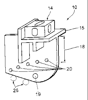
Fig. 1a shows, in a three-dimensional view, a first embodiment of a gripping
appliance
according to the invention. Device 10 comprises an attachment portion 12 and a
gripping portion 14 attached thereto. The attachment portion 12 has holes 20
as
attachment facilities with which the gripping devices 10 can be fastened to
the unit
load 16 (not shown in this figure) in a certain position, preferably by screw
connections.
An essential feature here is the spatial orientation, in particular the
distance 18
between the attachment facilities 20 and the gripping portion 14, in that this
also
results, for example, in the spacing between the unit load 16 (not shown in
this figure)
and a level base, when the unit load is set on the ground with a set of
gripping devices
10 as feet.
Because the invention with its advantages is also illustrated here in the
description of
the figures, for the example of a circular cylindrical section 16 of a steel
tower with
circular ring-shaped flanges at both ends thereof, the attachment facilities
20 (through
holes) adapted to said flanges are arranged in a pattern with curved centre
line.
When the spacing between the holes is identical, the device (10) according to
the
invention can be fastened to a flange of the section 16.
According to the invention, the gripping portion 14 is a so-called container
corner.
Said container corner is fixed to a support plate 15. Due to the fact that no
element of
CA 02415410 2003-O1-06
-10-
the gripping device projects beyond the container corner, the gripping device
can
serve as a hoisting point for appropriate hoisting means such as container
gantries or
container spreaders, and as a foot for setting down the unit load.
Owing to the possibility of using standardized fixing means for containers, it
is no
longer necessary to weld the feet to a ship's deck, for example. One can also
dispense with lashing down the unit load with chains as a way of securing it
during
transportation by ship.
Two plates 24 are attached in a indentation 22 in the attachment portion 12.
Said
plates are at an angle of a to each other and demarcate the sides of
indentation 22.
The plates each run vertically to the surface of attachment portion 12. In
this way, the
devices according to the invention can also be adapted as a set for setting
the unit
load 16 down on a boiler bridge and for cradling the support spars of the
boiler bridge
by conforming to their shape.
Figs. 1 b - a show alternative embodiments of a gripping device 10. Here, the
features
described with reference to Fig. 1 a are differently proportioned and
positioned in
relation to each other - e.g. by adapting to a differently dimensioned andlor
configured
transportation load (not shown). Fig. 1 c is the side elevation view of Fig. 1
b and
Fig. 1 a is the side elevation view of Fig. 1 d, whereby Figs. 1 b and 1 d
each show a
front view.
Fig. 2 shows yet another embodiment of a device according to the invention.
One
' significant difference to the device shown in Figure 1a consists in the fact
that
indentation 22 is not formed (as was already the case in Figs. 1 b - c).
Furthermore,
the portion between the attachment portion and the gripping portion is
embodied in a
shortened form. This embodiment cannot, therefore, be used as a foot for
setting
down the unit load on level ground, if, with the same fixing position of the
gripping
devices and the same diameter of the unit load, the outer contours of the unit
load
project beyond a conceived connection line between the gripping portions of
two
gripping devices. However, the device can easily be used as a hoisting point
for the
CA 02415410 2003-O1-06
-11-
unit load if it is attached to an upper edge of the unit load.
- Devices 10 shown in Fig. 1 and Fig. 2 each have an additional attachment
facility 19
at or in their first portions 12. Said attachment facility is configured here
as a through
hole, and other fixtures, for example stiffening struts, can be attached
hereto (cf.
Fig. 4).
Fig. 3 shows an adapter 30 according to the invention, comprising a total of
four
container corners as outer connector elements 34 and inner connector elements
35
mounted on a support 32. These outer and inner connector elements 34, 35 are
in
fixed positions on the support 32. The spacing 36 between the two outer
container
corners 34 is equal to the standard dimension of 2260 mm from centre to
centre. The
spacing between the two inner connector elements 35 is smaller. This means
that unit
loads onto which the gripping devices 10 according to the invention are
attached with a
smaller spacing than the standard 2260 mm due to the unit loads being of
smaller
dimensions can nevertheless be handled and transported by means of adapter 30
using standardized facilities for container handling and transportation.
Alternatively, in the case of a longer support 32, the inner connector
elements 35 can
have the standard spacing of 2260 mm and the outer connector elements 34 can
then
receive unit loads that only permit gripping devices 10 of the invention to be
fitted at
points beyond this standard dimension.
Fig. 4 shows one application of the devices 10 and an adapter 30 pursuant to
the
invention. The sections of a steel tower, shown as unit loads 16, are fitted
with a set of
gripping devices 10 and stacked one above the other. Due to their relatively
'small'
diameter, it is not possible to fit devices 10 with a spacing of 2260 mm
between the
centres of the container corners 14 of devices 10. Devices 10 are attached
with a
smaller spacing between their centres.
In order to enable the advantageous use of standardized facilities and
transport means
despite this smaller spacing, an adapter 30 is additionally provided under the
lower
CA 02415410 2003-O1-06
-12-
section. Said adapter is fitted in such a way that the inner connector
elements 35 have
the same spacing as the devices/appliances 10 attached to the lower section.
The
- outer connector elements 34 have the standard spacing and thus permit the
use of
existing facilities and transport means.
In order to provide a secure mechanical connection between the container
corners 14
of the set of gripping devices 10 attached to the lower section, on the one
hand, and
the adapter, on the other, and also between the container corners of the lower
section
and those of the upper section, standardized connector elements (not shown)
are
used such as those that are also used on conventional containers to connect
their
container corners directly with each other.
In the lower section, between the additional, diagonally opposite attachment
facilities
19 of the separate gripping devices 10, supports are attached that prevent the
lower
section from being deformed under the load of the upper section.
Fig. 5 shows transport means according to the invention, comprising a towing
vehicle
44, a low loader 45 and a trailer 42. Holding devices 40 for holding the unit
load 16
during transportation are disposed on the facing ends of the low loader 45 and
the
trailer 42. A connection is thus formed via the unit load 16 between the low
loader 45
and the trailer 42.
For a trip without a transportation load, the low loader 45 and the trailer 42
are
connected by a tow-bar 48 that engages with matching couplings on the low
loader 45
and the trailer 42 (bottom of Fig. 5).
On the right of Fig. 9, a horizontal support spar of the chassis of an
alternative
' transport means comprising a towing vehicle 102 can be seen, and on the left
of Fig. 9
a horizontal support spar of the chassis of an associated trailer 104 can be
seen, said
support spars ending respectively in holding devices 106, 108 for a unit load
(not
shown). At their lower end, holding devices 106, 108 have spars that project
horizontally towards other and which face each other in the direction of
travel. (110,
112) Spars 110, 112 are firstly used (like the container brackets 113 at the
upper end
CA 02415410 2003-10-24
-13-
of holding devices 106, 108) for attaching to a unit load (not shown) when the
towing
vehicle 102 and the trailer 104 are loaded with the unit load, and secondly,
in the
unloaded state as shown, for establishing a direct connection between the
towing
vehicle 102 and the trailer 104. Spars 110, 112 are each disposed as mutually
corresponding connector elements in such a way to the holding devices 10fi and
108
that they lie one above the other when directly connected, and are connected
with
horizontal flange surfaces 114 lying congruently one above the other.
Spars 110, 112, which are congruent in shape and form a cooperating connecting
structure, have on the one hand~a bolt 116 on flange surface 114 of spar 110,
said bolt
engaging, in the connected position as shown, with a holed 1.7~in the flange
surface
114 or spar 1 12, ~ This connection formed by conforPnity of shape is secured
by tv~io tensioning ele~rients 1 18 that are stretched between eyes 120 on the
holding devices ~106,~ 108 in such a way that the towing vehicle 102 and the
trailer 104 are rigidly clamped to each other.
In Fig. 6, the holding device 40 in Fig. 5 can be seen more precisely in the
form of a
vertically disposed base frame that has .two vertical stays 2 and two
horizontal
Traverses ~.. On either side of the lower traverse 4, extension arms 5 with
hydraulic
cylinders 8 can be telescopically withdrawn and extended in the direction of
traverse 4
(horizontally and laterally thereto). In stay 2 there are stay extensions 3
that can
similarly be withdrawn and extended with the aid of hydraulic cylinders 8 in
the
longitudinal direction of stays 2 (vertically upwards). On stay extensions 3
there is then
a crossbeam 6, at the outer ends of which container brackets 7 - standardized
facilities for rapid engagement with container corners - are attached.
Additional
container brackets 7 are Ibcated at the ends of the horizontally and laterally
extendable extension arms 5. The position of said extension arms can be seen
particularly well in Fig. 7.
It is also clearly apparent from Fig. 7 that the outer portions of said
extension arms 5
run at a right angle to the respective extension arm 5 in the direction of the
respective
holding device 40 facing the extension arm on the transport vehicle. The
container
i
CA 02415410 2003-10-24
-14-
brackets 7 are disposed on said angled portions of extension arms 5 in such a
way,
therefore, that operating the lower hydraulic ~ cylinder 8 causes the lower
container
brackets 7 to be laterally displaced. By this means, the holding device 40
according to
the invention can be adjusted to the width and/or to the spacing between the
devices
and the unit load 16.
The side elevation view in Fig. 8 also shows the holding device 40 on the low
loader
45 and the trailer 42. It can easily be seen from this view that operating the
upper
hydraulic cylinder 8 causes- extensions 3 to be extended from stays 2
arlij~ hence a change in the height of the upper container brackets 7 disposed
on the crossbeam 6.
The crossbeam 6 can also cori~prise a plurality of laterally adjacent
container
brackets 7, or rriay also enable telescopic adjustment in this direction such
that, in addition to hydraulic (or pneumatics adjustment of height, the
horizontal
Lateral position of the upper container brackets can also be adapted
to the transportation load.