Note: Descriptions are shown in the official language in which they were submitted.
CA 02415515 2002-12-30
METH()() AND AP~'AIZA'rCJS FOIZ INJEC'rfION M()1.,DING
I3AC:KGROUND
The present invention relates to a IllethOd and apparatus for injection
wolding, and in particular, to a method an<l apparatus for molding injection
naoldcd parts.
Conventionally, a variety of nlethocis have been utilized for injection
molding in various fields. ()f these methods, a molding 111etal mold of a
runnerless
(hot runner) system has been widely used.
There are a variety of I1701dS 111 SL1C11 a hot runner system. Smaller molds
1 () generally only require one inlet fun- injecting molten noaterial. For
larger molds,
several inlets are used to inject molten material at different points within
the mold
cavity. These larger molds are sometimes referred to as multi-gate mold
cavities.
In multi-gate mold cavities, the pressure of molten material differs at
various
points inside the cavity. The pressure typically becomes constant throughout
the
cavity once the cavity is cotnplctc°ly filled with molten rnatcrial_
A conventional molding process can be done using power from hydraulic
rmeans or electrical means. The molding process uses two platens, a movable
platen and a stationary platen. In a process using hydraulic means, a
hydraulic
cylinder applies a certain force to push a movable platen against a stationary
platen. Molding members within or attached to the platens form a molding
cavity.
The force is maintained on the staticmary platen or die plate while a molten
material is injected into the molding cavity. The molten material is injected
into
the cavity with a resin feeding screw until the pressure inside the cavity
reaches a
predeter-mined molding pressure or until the screw has moved a predetermined
distance and for a set period of tune, thereby ensuring that the cavity is
filled.
After injecting the molten material, the molten material is allowed to cool
and
solidify, the force is then released, and the plates arc separated and the
process
begins anew.
CA 02415515 2002-12-30
_7_
Some injection molding machines use a mold with only one cavity, thereby
allowing Ii>r the production of one molded object per cycle. 'Total cycle time
is the
sum of the fill time and the cool clown tune. 1'he cool do>wn time is
generally
substantially longer than the fill time. For example, a typical fill tinge is
about 5
seconds, whereas a typical cooling time is about 30 seconds, for a total of
about 35
seconds for the; production of one molded article.
To reduce process time per molded article, some injection holding
machines utilise molds with a plurality of cavities for forming a plurality of
molded articles. 'The molten material fills into eacin of the cavities
simultaneously.
l 0 While this may extend the fill tirnc a few seconds, for example for mold
cavities
for car doors, to about 8 seconds, the cooling tlrlle I'ca~lallls fixed at
about 40
seconds. 'The total time of this prr>cess is about 48 seconds for the
production of
two molded articles. 'Thus, using multiple cavities increases the efficiency
almost
two-fold.
A problem with the multiple cavity method, however, is that the mold
clamping force must also be doubled since the article molding area is doubled.
As
a result, a larger injection molding machine must be used to apply the extra
force
needed to hold the molding platens together. A larger 111~eCt1011 I710Id1n~
machine
costs more, takes up more floor space, and requires more power. Therefore,
using
2() multiple cavity molds with the; conventional method can sacrifice cost for
greater
time efficiency.
Furthermore, for molding larger articles, the molten material is injected at
several different points in the n gold cavity. 'This is due to the limits on
the flow of
molten plastic. These larger hold cavities arc commonly known as multi-gate
mold cavities. An example of an article that would require a multi-fate mold
cavity is an interior car door p~illc'l, which typically requires four or live
gates per
single cavity mold. In the manufacture of s~_rch parts, it is desirable to
maintain the
injected pressure of the molten material constant so that the part is fc:~rmed
accurately. Without maintaining the pressure constant, the structural accuracy
of
~0 the formed part may suffer. For exahple, the resulting part may include
short
CA 02415515 2002-12-30
shots, ripples, or other dimensional inaccuracies. As such, there is a need to
be
able to accurately measure the pressure of molten plastic inside of the mold
cavity.
Accordingly, a general ob~cct of the present invention is to provide an
injection molding machine and a method for injection molding either large or
small articles where there is process control for each cavity..
A further object of the present invention is to provide an injection molding
machine and a method for injection molding large articles with greater
efficiency
and reduced costs.
I3RlEF SUMMARY
In one aspect, the invention is a method for sequentially injecting a molten
material comprising clamping a stationary platen and a movable platen at a
clamping force to define at least two cavities, opening a first valve gate to
inject a
molten material into a first cavity, closing the first valve gate either by
position,
time or pressure switch, opening a second valve gate to inject the molten
material
into a second cavity, and closing the second valve gate when the desired
position,
time or pressure switch value has been rnet.
In a second aspect, the invention is an injection molding apparatus
comprising a mold having at least two mold cavities, a molten material inlet
system in communication with said at least two mold cavities, at least two
valve
1f1 gates in said molten material inlet, wherein each of said at least two
valve gates
are associated with one of said mold cavities; and a controller adapted to
sequentially open and close said valve gates.
In a third aspect, the invention is a controller for use with a injection
molding device having a mold will at least two cavities, the controller
comprises
1S means for opening a first valve gate associated with a first mold cavity to
initiate a
flow of molten material into the first mold cavity, means for closing the
first valve
gate by either position, time or prcasure switch, means for opening a second
valve
gate associated with a second cavity to initiate a flow of molten material
into a
second mold cavity, and means for closing the second valve gate by either
;~0 position, time or pressure switch.
CA 02415515 2002-12-30
-4-
Other objects, features and advantages of the present invention will become
apparent from the following detailed description. It should be understood,
however, that the detailed description and the specific examples, while
indicating
embodiments of the invention, are given by way of illustration only, the
invention
being defined only by the claims following this detailed description.
BRIEC DESC.'RIPrI'ION ()F SI~,VI?RAI~ VIEWS OF rhI-IE DRAWINGS
'fhe following drawings form part of the present specification and are
included to further demonstrate certain aspects of the present invention. The
invention may be better understood by reference to one or more of these
drawings
in combination with the detailed description of specific embodiments presented
herein:
FIG. I is a schematic view of an injection molding apparatus suitable fox
the method of injection molding a molten material, provided by the present
mventron.
FIG. 2 is a schematic view of a part of the injection molding apparatus
showing a state immediately after clamping the mold, and a state in which the
introduction of the molten material is initiated, in the method of injection
molding,
provided by the present invention.
FIG. 3 is a perspective view of a part of the injection molding apparatus
showing a mufti-gate injection molding system with multiple mufti-gate molds,
in
the method of injection molding, provided by the present invention.
FIG. 4 is a flowchart illustration of the sequential injection molding process
of the present invention.
FIG. 5 schematically shows a change in injection velocity with time for a
conventional injection molding method and a sequential injection molding
171ethOd.
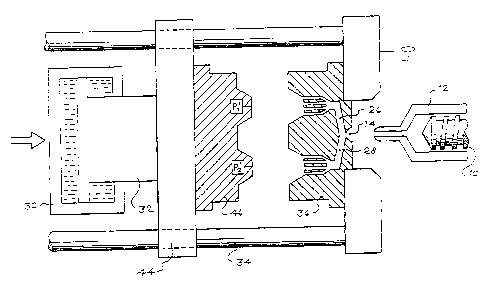
DE'I'AII_,ED DESCRIPTION OF THE 1'REFERRFD EMBODIMENTS
First, the injection rr~olding apparatus suitable for use in the method of
injection-molding a thermoplastic or thermosct resin, provided by the present
CA 02415515 2002-12-30
invention, will be outlined below with refc;rence tco FIG. 1. Although the
injection
molding apparatus described and shown in FICi. 1 uses hydraulic power, one of
ordinary skill in the art would recognirc that an electrically powered molding
apparatus can also be used for the present invention. 'f'he injection molding
apparatus includes an injection cylinder 12 having a resin-feeding screw or
extrusion screw 10 inside, a stationary platen 40, a movable platen 44, an
inlet 26,
tie bars 34, a clamping hydraulic cylinder 30 and a hydraulic piston 32. 'fhe
movable platen 44 is actuated with the hydraulic piston 32 in the hydraulic
cylinder 30 to move in parallel on the tie bars 34.
A mold is formed by a stationary mold member 36 and a movable mold
member 46. The stationary mold member 36 is attached to the stationary
platen 40, and the movable mold member 46 is attached to the movable platen
44.
The platens 40, 44, the tie bars 34, and the cylinder 30 and piston 32 define
a
clamping system for applying a clamping pressure to the mold members 36, 46.
The movable platen 44 is moved towards the stationary platen 4U until the
movable mold member 46 is engaged with the stationary mold member 36, and the
mold is clamped to form multi-gate cavities 22, 24. This clamped position is
illustrated in FICJ. 2.
After the mold has been clamped, the clamping force is controlled with the
2() clamping hydraulic cylinder 30. The clamping force may also be controlled
by
toggle or an electric machine. 'The molten material flows into the cavities
22, 24
via inlets 26. Valve gates 50, 52 may be used, but are not necessary, to open
and
close inlets 26. If used, valve gates 50, 52 would face cavities 22, 24 and at
least
one valve gate is associated with each cavity 22, 24 respectively. After the
molten
material cools and hardens, the clamping force is released and the movable
platen 44 is moved away li~om the stationary platen 40, in order to release
the
molded product.
For the exemplary two-cavity multi-gate n gold shown in FIG. 2, the
sequential injection molding meshod begins with clamping the mold with at a
mold clamping force. The controller 60 then closes valve gate 52 and opens
valve
gate 50. Molten material fills cavity 22. The amount of material that enters
the
CA 02415515 2002-12-30
cavity may be controlled by the. use <.~f pressure transc.lucers ('1, P2 or
preferably
can be controlled by predetermining the d~stanee or tune the resin feeding
screw
must travel to fill cavity 22. ('onventional molding processes use the
position
of the resin feeding screw 10 to control the amount of material being injected
into
S the mold cavity and to ensure that tlne cavity is full acrd packed.
Sametirnes, the
time the screw travels is the controlling variable in tilling the cavity.
As molten material enters through the inlet, it gradually fills the entire
cavity. A stroke sensor or potentiometer 65 measures the distance resin
feeding
screw lU has moved and transmits this reading to the controller 60. The
controller
10 60 uses the data from the stroke sensor and/or a timer to determine when to
close
valve gate 50 to stop the flow of molten material into cavity 22 an<i open
valve
gate 52 to start the flow of molten noaterial into cavity 24. 'fhe controller
closes
valve gate 50 when the resin feeding screw has traveled a pre-determined
distance
or for a predetermined period of time. If no hold pressure is used in molding
the
L 5 article, the valve gate 50 is closed at the switchover point which is the
point when
the entire cavity gets filled with molten material and begins to exert a
pressure on
the cavity. If a hold pressure is used, the valve gate is kept open for a
fixed period
of time after the molten material has filled the entire cavity and the resin
feeding
screw exerts a holding pressure. After the ~xcd period of time the valve gate
50 is
closed. If pressure transducers are used, the controller closes valve gate 50
and
opens valve gate 52 when the pressure inside the cavity reaches a set point
pressure. The controller opens valve gate 52 and the resin feeding screw may
then retreat back or may continue from its end position depending on whether
or
not there is enough material in the injection chamber to fill the second
cavity 24.
fn a preferred embodiment, the pressure exerted by the resin feeding screw is
decreased between the closing of valve gate SU and the opening of valve gate
52.
In the alternative, the screw is activated after del<ry time of about 0.5
seconds after
opening valve gate 52. This prevents a sudden high pressure shot upon the
opening of valve gate 52 and provides greater control of the process. Molten
material then fills into cavity 24. When the resin feeding screw 10 has moved
the
predetermined distance or time to fill ancf pack cavity 24, the molten
material is
CA 02415515 2002-12-30
-7-
held inside cavities 22, 24 and is allowed to cool and solidify. At this
point, valve
gate 52 may be left open if' there arc no additional mold cavities to he
utilized,
otherwise the controller closes valve gate 52 and the process repeats.
FIG. 3 shows a perspective view an embodiment of the multiple multi-gate
S mold injection system of the present invention. In particular, there are two
multi-
gate mold cavities for interior car door panels 71. Wolten material enters
into the
main inlet 75 and then flows into the mufti-drop hot manifold 76 that has
inlets at
various points in the mold cavity. Pressure transducers 73rnay be placed
inside the
cavity, preferably at the end of till point 72, to measure the pressure inside
the
1 () cavity. Ejector pins 74 release tile molded article once the molten
material cools
and solidifies.
FIG. 4 is a tlowchart illustration of the sequential injection molding process
of the present invention. It will be understood that each step of the
flowchart
illustration can be implemented by computer program instructions or can be
done
15 manually. These computer program instructions may be loaded onto a computer
or other programmable data processing apparatus to produce a machine, such
that
the instructions which execute nn the computer or other programmable data
processing apparatus create means for inoplementing the functions specified in
the
flowchart step. Tlrcsc computer program instructions may also be stored in a
2.(t computer-readable memory that can direct a computer or other programmable
data
processing apparatus to function in a particular manner, such that the
instructions
stored in the computer-readable memory produce an article of manufacture
including instruction means which imptc:ment the function specified in the
flowchart step. ~IVhe computer program instructions may also be loaded onto a
25 computer or other programmable data processing apparatus to cause a series
of
operational steps to be performed on the computer or other programmable data
processing apparatus to cause a series of operational steps to be performed on
the
computer or other programmable apparartus to produce a computer implemented
process such that the instructions which execute on the computer or other
30 programmable apparatus provide steps for implementing the functions
specified in
the flowchart step.
CA 02415515 2002-12-30
It will be understood that each step of the filowchart illustration can be
implemented by special purpose hardware-based computer systems which perform
the specified functions cor sups, or comb in<ttions of special purpose
hardware and
computer instructions, or can be clone; ntanually~
An injection molding machine utilizing a sequential injection molding
process has a plurality of mufti-gate mold cavities formed by the movable mold
member 46 and the stationary mold member 36_ For an injection molding
machine with m cavities, where n equals I to m, the process begins with step
100
by closing the clamp with a mold clamping force calculated by the equation:
1 () mold clamping force required = (clamp tonnage required per square inch) x
(surface area of cavity n)
The clamp tonnage is predetermined and is calculated based upon the type of
molding material and the desired characteristics of the molded article. For
15 example, an ABS material may require two to three tons of~pressure per
square
inch of area. Other materials require different amounts of pressure. In step
110, a
first valve gate is opened which faces a first cavity. he first cavity is then
injected with molten material using a resin-feeding screw at a predetermined
injection velocity in step 120. The injection velocity may be changed or may
be
20 kept constant as the cavity becomes filled with molten material. The time
it takes
to fill the cavity to the V/P change over position or the set-point pressure
depends
on the size of the cavity and the injection velocity. )n a preferred
embodiment, the
injection velocity is varied and it takes about one second to about ten
seconds to
fill the cavity to the set-point pressure or V/P change over position. In step
130,
25 the controller monitors the distance, time and/or velocity at which the
resin screw
has moved and compares it to the set-point values said screw must move in
order
for molten material to fill the cavity or reach the velocity to pressure (V/P)
switch
point. 'Che V/P sv~.~itch point occurs when the n Molten material has fully
filled the
cavity and begins to exert a pressure inside the cavity. In one embodiment, if
a
30 predetermined holding pressure at which the material must be held is used,
resin
feeding screw exerts a holding pressure for a predetermined time before the
controller closes the valve gate to the cavity.. 'rhe process goes back to
step 120 if
CA 02415515 2002-12-30
the cavity is not full or has not reached the V/P switch point if there is no
holding
pressure, or has not reached a predetermined holding pressure if using holding
pressure or has not reached the pressure switch set value. The first valve
gate is
closed once the cavity is full if not using holding pressure or once it is
full and has
been held for a predetermined period of time at a holding pressure or has
reached
the pressure switch set value in step 140. The process goes back to step 110
and
repeats for rZ cavities. After all of the cavities are full, the machine
recovers for
the next shot in step 150 the molten material inside the cavities is allowed
to cool
and solidify in step 160. The Gaoling process takes about 20 seconds to about
40 seconds, depending upon the size of~ the molded article and the type and
temperature of the molded material. After cooling, the mold clamping force is
released and the clamp is opened in step 17U. 'rhe sequential injection
molding
process ends with step 180, when the molded articles are ejected from the
molding
cavities.
The mold clamping force required is reduced significantly in a sequential
injection molding process for a multiple cavity mold. rfhis is because the
area to
be pressurized does not increase when there are multiple cavities. For a mold
with
multiple cavities, the area to be pressurized remains constant and equals the
area
of one cavity since each cavity in the rmold is pressurized and closed
sequentially.
2() Therefore, the mold clamping force required in a two-cavity mold is
reduced to
almost half by using the sequential injection molding method compared to a
conventional method. The mold clamping force required in a three-cavity mold
the force required is reduced by over fifty percent compared to the force
required
in the conventional method. This significant reduction in mold clamping force
allows for a reductian in the press size, which In turn allows for dramatic
cost
savings in terms of production cost per molded article.
FIG. 5 shows how the injection velocity varies during the step of filling a
cavity for a standard injection holding process compared to a sequential
injection
molding process in a two-cavity mild. 'The injection velocity is controlled by
the
3(> machine set-point of the resin-feeding screw 10. In a standard injection
molding
process the cavities are filled with molten material simultaneously and in the
CA 02415515 2002-12-30
sequential method the cavities are filled sequentially. Both processes may be
carried out with more than two cavities. 'I~he sequential noolding process,
however, has at least two cavities.
In a standard rll~eCtlOr7 mOldlrlg process, the injection pressure is set
above
the necessary pressure requrirement to till the mold cavity. 'hhe injection
velocity
of the molten material is set at a filling flow rate prior to the valve gate
being
opened. As illustrated in FICA. 5, the injection velocity is kept at filling
flow rate
until the cavities are almost full. The injection velocity is then gradually
tapered
down from the filling flow rate so that the injection velocity of the molten
material
can be controlled to allow proper fill of the entire cavity. Once the pressure
inside
the cavity reaches the set-point molding pressure, the injection velocity is
brought
down to zero or if molding by position when the cavity reaches the desired
fill
level. Decreasing the injection velocity ensures that the molten material is
uniform inside the cavities, thereby yielding a higher quality molded article.
I S In the sequential injection molding process, the injection pressure is set
above the necessary pressure requirement to fill the mold cavity. rfhis
pressure
requirement is dependent on the physical properties of the molten material
such as
its viscosity. The injection velocity of the molten material is set at a
filling flow
rate when a valve gate is opened. The injection velocity is kept at the
filling flow
2() rate until a cavity is almost full and then gradually tapered down until
the cavity is
full at the switchover point or if holding pressure is utilized until the hold
timer
times out. The difference in the sequential method compared to the standard
method, is that the injection velocity is increased again to the filling ftow
rate
when the second valve gate is opened. 'l~his acids approximately 0.5 seconds
to
25 about 4 seconds to the total fill-time for the process. In a preferred
embodiment,
the ramp up of the injection velocity to the filling flow rate is rapid so
that the total
process time does not increase significantly.
It is contemplated that numerous modifications may be made to the
injection molding method and atpparatus of the present invention without
departing
~() from the spirit and scope of the invention as defined in tt~e claims. For
example,
while the exemplary ernbOdlrrlCllt shown in the drawings has two mufti-gate
mold
CA 02415515 2002-12-30
cavities, those. skilled in the art will appreciate that the satme sequential
steps can
be used to control the flow of molten material into molds having more than two
cavities. In addition, for molds lrtvin~ more than twc~ cavities, there may be
a
valve gate associated with each cavity, with each valve gate opened and closed
sequentially. Alternately, for molds having more than two cavities, there may
be
f'cwc:r valve gates than cavities, as Iong as there are at least two cavities.
In this
embodiment, at least one of the valve ~;atca would control the inlet to at
least two
cavities. Accordingly, while the present invention has been described herein
in
relation to several embodiments, the foregoing disclosure is not intended or
to be
I O construed to limit the present invention or otherwise to exclude any such
other
embodiments, arrangements, variations, or modifications and equivalent
an-ang;ernents. Rather, the present invention is limited only by the claims
appended hereto and the equivalents thereof.