Language selection

Search

Patent 2415898 Summary

Third-party information liability

Some of the information on this Web page has been provided by external sources. The Government of Canada is not responsible for the accuracy, reliability or currency of the information supplied by external sources. Users wishing to rely upon this information should consult directly with the source of the information. Content provided by external sources is not subject to official languages, privacy and accessibility requirements.

Claims and Abstract availability

Any discrepancies in the text and image of the Claims and Abstract are due to differing posting times. Text of the Claims and Abstract are posted:

  • At the time the application is open to public inspection;
  • At the time of issue of the patent (grant).
(12) Patent Application: (11) CA 2415898
(54) English Title: CASE-HOLDERS
(54) French Title: PORTE-BOITIERS
Status: Deemed Abandoned and Beyond the Period of Reinstatement - Pending Response to Notice of Disregarded Communication
Bibliographic Data
(51) International Patent Classification (IPC):
  • A47B 97/00 (2006.01)
  • G11B 23/023 (2006.01)
  • G11B 33/00 (2006.01)
  • G11B 33/04 (2006.01)
(72) Inventors :
  • WHITE, MATTHEW EDWARD THOMAS (United Kingdom)
(73) Owners :
  • MATTHEW EDWARD THOMAS WHITE
(71) Applicants :
  • MATTHEW EDWARD THOMAS WHITE (United Kingdom)
(74) Agent: SMART & BIGGAR LP
(74) Associate agent:
(45) Issued:
(22) Filed Date: 2003-01-02
(41) Open to Public Inspection: 2004-07-02
Availability of licence: N/A
Dedicated to the Public: N/A
(25) Language of filing: English

Patent Cooperation Treaty (PCT): No

(30) Application Priority Data: None

Abstracts

English Abstract


A holder for displaying a CD or DVD case (10) has a bowed
configuration with regions (4) sloping up to a central,
flat region (5) between a pair of opposed, hooked lugs
(2). The back-face (11) of the case (10) rests on the
region (5) between upturned lips (6) and the lugs (2)
bear resiliently on opposite edges (13,14) of the case
(10) to retain it firmly. Rocking of the case (10) frees
the projecting rim (16) of the edge (13) from the hook-
end (7) of the abutting lug (2). Alternative holders
have a central spine (22;45) with laterally-extending
legs (23,25;41,43) that terminate in hooked-lugs (24;42)
or plain lugs (26;44), and have a wave-contour for back-
support of the case (30).


Claims

Note: Claims are shown in the official language in which they were submitted.

6
Claims:
1. A case-holder comprising means for defining a
backing member against which the case is to be retained
in a mutually-abutting relationship, and a pair of
opposed lugs upstanding from said member, the lugs being
spaced apart from one another for receiving the case
between them, and wherein the lugs have resilience so as
to abut opposite edges of the received case tightly for
retaining it between them on the member.
2. A case-holder according to Claim 1 wherein the means
defining the backing member is configured to allow
rocking of the case on the backing member while it
remains abutted by the lugs, such as to facilitate
freeing of the case from the holder.
3. A case-holder according to Claim 2 wherein the means
defining the backing member is of a generally-bowed
configuration with a substantially flat central-region
for abutment by the back of the case.
4. A case-holder according to Claim 3 wherein the
central-region is separated from each individual lug by a
region of said member that slopes up from the lug to the
central region.
5. A case-holder according to Claim 3 or Claim 4
wherein the central-region has upturned lips for
restraining the case from movement laterally of the pair
of lugs.
6. A case-holder according to Claim 1 or Claim 2
wherein the means defining the backing member has the

7
form of a central spine with one or more legs extending
in each of opposite lateral directions from it, and
wherein the lugs are provided as lugs that terminate
respective ones of the legs.
7. A case-holder according to Claim 6 wherein the legs
are of wave-configuration for abutment by the back of the
case.
8. A case-holder according to any one of Claims 1 to 7
wherein one or both of the lugs of the pair is of hook
form for engagement with a projecting rim of the case.
9. A case-holder according to any one of Claims 1 to 8
including one or more further pairs of opposed lugs
upstanding from the backing member for receiving the case
between them, the lugs of each further pair having
resilience so as to abut opposite edges of the received
case tightly for retaining it between them on the backing
member.
10. A case-holder according to any one of Claims 1 to 9,
in combination with a CD or DVD case, the case being
retained in abutting relationship with the backing member
and with the lugs abutting opposite edges of the case
resiliently.

Description

Note: Descriptions are shown in the official language in which they were submitted.


CA 02415898 2003-O1-02
1
Case-Holders.
This invention relates to case-holders, and particularly,
though not exclusively to holders for the cases of CDs
(compact disks), DVDs (digital versatile disks), Mini-
Discs, audio tapes and video tapes.
According to the invention a case-holder comprises means
for defining a backing member against which the case is
to be retained in a mutually-abutting relationship, and a
pair of opposed lugs upstanding from said member, the
lugs being spaced apart from one another for receiving
the case between them, and wherein the lugs have
resilience so as to abut opposite edges of the received
case tightly for retaining it between them on the member.
The means defining the backing member may be configured
to allow rocking of the case on the backing member while
it remains abutted by the lugs, such as to facilitate
freeing of the case from the holder. In this respect the
means defining the backing 'member may be of a generally-
bowed configuration with a substantially flat central-
region for abutment by the back of the case.
Alternatively, the means defining the backing member may
have the form of a central spine with one or more legs
extending in each of opposite lateral directions from it,
and in this event the legs may be of wave-configuration
for abutment by the back of the case.
One or both of the lugs of the pair may be of hook form
for engagement with a projecting rim of the case, and one
or more further pairs of lugs may be provided for
resilient abutment with the: case.

CA 02415898 2003-O1-02
2
Three case-holders in accordance with the present
invention will now be described, by way of example, with
reference to the accompanying drawing, in which:
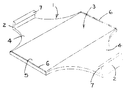
Figure 1 is a perspective view of a first case-holder
according to the present invention;
Figures 2 is a side elevation of the case-holder of
Figure 1;
Figures 3, 4 and 5 are, respectively, a perspective view,
a side elevation, and an end elevation of the case-holder
of Figures 1 when in use holding a case;
Figure 6 is a perspective view of a second case-holder
according to the present invention;
Figures 7 and 8 are, respectively, a perspective view and
a side elevation of the case-holder of Figure 6 when in
use holding a case; and
Figure 9 is a perspective view of a third case-holder
according to the present invention.
Each of the case-holders to be described with reference
to the drawings is for use in retaining the transparent-
plastics case of a CD or DVD in p7_ace, in storage or
otherwise. More particularly, it is for holding the case
for display face-on, that is to say to present it with
its front-face or lid, and therefore the card-insert
within the transparent lid, in full view. This allows
the benefit of display of the wording and main artwork of
the card-inset to be realised while the case is being
retained, for example while mounted on a wall or other
structure. The presentation of the retained case face-on
in this way is distinct from the usual way of retention
in which the case is held edge-on so that it is the

CA 02415898 2003-O1-02
3
limited wording arid artwork of the spine-inset alone that
can be seen.
Referring to Figures 1 and 2, the first case-holder is in
the form of a plastics or metal plate 1 having a pair of
upstanding lugs 2 that oppose one another from either
side across the upper surface 3 of the plate 1. The
plate 1 is of a generally-bowed configuration giving~the
surface 3 sloped regions 4 that run upwardly from the
individual lugs 2 into a flat, central region 5 that has
a small up-turned lip 6 front and back. The lugs 2 have
inwardly-turned ends 7, and although inclined slightly
inwardly towards one another have resilience to enable
them to be flexed to a small extent. outwardly from this
rest attitude.
The plate 1, which may be mounted, for example, on a wall
or other vertical support structure, is used to hold a CD
or DVD case as illustrated in Figures 3 to 5.
Referring to Figures 3 to 5, the rectangular CD or DVD
case 10 is inserted between the lugs 2 with its back-face
11 abutting the central region 5 and its longer, side
edges 12 just within the up-turned lips 6. The lugs 2
bear hard on the front, lid-opening edge 13 and spine 14
of the case 10 so as to retain the case 10 tightly within
the holder with its front-face or lid 15 in full view.
The inwardly-turned ends 7 of the lug 2 that bears on the
edge 13 clips over the projecting rim 16 of the back-face
11, to ensure retention. The lips 6 restrain the case 10
from sliding out laterally from between the pair of
retaining lugs 2, and .in this condition the lid 15 can be
freely opened and closed and the CD or DVD within removed
and replaced as desired.
Removal of the case 10 from the holder is facilitated by
the bowed configuration of the plate 1. More

CA 02415898 2003-O1-02
4
particularly, this configuration of surface 3 with the
central, raised region 5 separated by the sloping regions
4 between the lugs 2, allows the case 10 to be rocked to
one or other side (about the: junction line of region 5
with one or the other of the regions 4) to free the edges
13 and 14 from engagement with the lugs 2. During this,
the lugs 2 flex outwardly to the extent necessary to
enable the projecting rim 1~ to ride over the lug 2 at
the edge 13 so as to release the case 10 from the holder.
The case 10 can be replaced in the holder simply by
urging its back-face 11 onto the lugs 2 so as cause them
to flex outwardly until the face 11 is admitted to abut
the region 5.
Although the case-holder described with reference to
Figures 1 to 5 involves just one pair of opposed lugs 2,
more than one pair may be provided to engage the case.
This is illustrated by the second case-holder to be
described with reference to Figures 6 to 8.
Referring to Figures 6 to 8, the case-holder 21 in this
instance has a central spine 22 with two legs 23 which
each terminate in a hook-lug 24, extending laterally in
opposite directions from it. Three further legs 25 which
terminate in plain lugs 26, also extend laterally from
the spine 22, two in one direction and one in the other.
The spine 22 itself is terminated at opposite ends in a
hook-lug 27 and a plain lug 28.
The spine 22 is flat but the legs 23 and 25 have a wave-
contour such that a case 30 retained resiliently between
the lugs 24, 26, 27 and 28, rests on the crests of the
contour (see especially ficfure 8). The hook-lugs 24 and
27 engage over the peripheral rim 31 of the case 30 to
enhance retention. Rocking the case 30 on the crests of
the legs 23 and 25 enables it to be freed from retention.

CA 02415898 2003-O1-02
A case-holder having just two legs on a central spine is
illustrated in Figure 9.
Referring to Figure 9, the case-holder 40 in this example
5 has a single leg 41 terminating in a hook-lug 42, and a
single leg 43 terminating in a plain lug 44. The two
legs 41 and 43 are of wave-contour and extend in opposite
directions from a flat spine 45 that terminates at one
end only, in a plain lug 46.
When this case-holder is mounted on a wall or other
vertical surface, mounting is with the spine 45 extending
downwardly so that the case inserted into the holder is
restrained from sliding out. from between the lugs 42 and
44 by the lug 46. Here again, the retained case rests on
the crests of the legs 41 and 43 and can be freed by
rocking it on them.

Representative Drawing
A single figure which represents the drawing illustrating the invention.
Administrative Status

2024-08-01:As part of the Next Generation Patents (NGP) transition, the Canadian Patents Database (CPD) now contains a more detailed Event History, which replicates the Event Log of our new back-office solution.

Please note that "Inactive:" events refers to events no longer in use in our new back-office solution.

For a clearer understanding of the status of the application/patent presented on this page, the site Disclaimer , as well as the definitions for Patent , Event History , Maintenance Fee  and Payment History  should be consulted.

Event History

Description Date
Inactive: IPC from MCD 2006-03-12
Application Not Reinstated by Deadline 2006-01-03
Time Limit for Reversal Expired 2006-01-03
Deemed Abandoned - Failure to Respond to Maintenance Fee Notice 2005-01-04
Application Published (Open to Public Inspection) 2004-07-02
Inactive: Cover page published 2004-07-01
Inactive: First IPC assigned 2003-03-13
Inactive: IPC assigned 2003-03-12
Application Received - Regular National 2003-02-14
Inactive: Filing certificate - No RFE (English) 2003-02-14
Correct Applicant Requirements Determined Compliant 2003-02-14

Abandonment History

Abandonment Date Reason Reinstatement Date
2005-01-04

Fee History

Fee Type Anniversary Year Due Date Paid Date
Application fee - standard 2003-01-02
Owners on Record

Note: Records showing the ownership history in alphabetical order.

Current Owners on Record
MATTHEW EDWARD THOMAS WHITE
Past Owners on Record
None
Past Owners that do not appear in the "Owners on Record" listing will appear in other documentation within the application.
Documents

To view selected files, please enter reCAPTCHA code :


To view images, click a link in the Document Description column. To download the documents, select one or more checkboxes in the first column and then click the "Download Selected in PDF format (Zip Archive)" or the "Download Selected as Single PDF" button.

List of published and non-published patent-specific documents on the CPD .

If you have any difficulty accessing content, you can call the Client Service Centre at 1-866-997-1936 or send them an e-mail at CIPO Client Service Centre.


Document
Description 
Date
(yyyy-mm-dd) 
Number of pages   Size of Image (KB) 
Description 2003-01-01 5 193
Abstract 2003-01-01 1 19
Claims 2003-01-01 2 65
Drawings 2003-01-01 4 65
Representative drawing 2003-03-19 1 9
Filing Certificate (English) 2003-02-13 1 159
Reminder of maintenance fee due 2004-09-06 1 110
Courtesy - Abandonment Letter (Maintenance Fee) 2005-02-28 1 174