Note: Descriptions are shown in the official language in which they were submitted.
CA 02416078 2003-O1-09
884.0094USP
HEIaD GENT STE~MEFt
BACKGROUND OF THE INVENTION
1. Field of the Invention
The present invention relates to a hand held appliance for
the care of garments and other items made of fabric. More
particularly, the present invention relates to a hand held
appliance for applying steam and/or heat to garments, fabrics and
the like.
2. Description of the Prior Art
Portable hand held devices for applying steam are
particularly useful in removing wrinkles and generally improving
the appearance of hanging garments;, draperies, upholstery, and
other items made of fabric. When traveling, these devices may be
especially effective for freshening clothes that have been packed
in luggage. They are also useful for improving the appearance of
hanging draperies without removing them, straightening and
flattening upholstery, opening seams, and generally for smoothing
fabric during sewing operations. In all of these applications,
it is not only important to apply steam to the fabric, but to do
so in a safe, easy manner. It is also important to be able to
apply a desired amount of steam to a particular portion of the
fabric being treated.
- 1 --
CA 02416078 2003-O1-09
884.0094USP
There are several factors that make the steaming operation
difficult. An appliance that is large may occupy a significant
amount of space rendering it unsuitable for use when traveling.
An appliance that is bulky and heavy may be difficult to
manipulate and thus inhibit applying the proper amount of steam
for the time required to remove wrinkles. In addition, a bulky
appliance may make it difficult to operate the controls. An
appliance that does not accommodate different voltages
encountered in different countries may be inconvenient. Also,
the construction of the appliance may make filling with water
difficult and may require a user to carry the entire appliance to
a source of water. Certain types of fabric may also require an
additional operation during the steaming operation such as the
application of pressure over an area, brushing, or scrubbing.
The present invention provides for a hand held device that
addresses the above-identified limitations. The present
invention is suitable for use in traveling because of its small
profile. It is lightweight and designed to be held comfortably
by as user to facilitate the application of steam and/or heat.
The controls are constructed to allow a consistent application of
steam and/or heat. The present invention may be constructed to
accommodate multiple voltages that may be found in different
locations of the world. A detachable reservoir is provided that
eliminates the need to transport the entire appliance to the
water source for filling. In addition, the present invention may
_ 2 _
CA 02416078 2003-O1-09
884.0094USP
include one or more attachments allowing a user to apply pressure
and heat to the item, or to perform brushing, scrubbing, or lint
removal operations while steaming.
STII~fARY OF THE INVENTION
It is an object of the present invention to provide a hand
held device, or appliance, for applying steam to an item.
It is another object of the present invention to provide an
appliance that is relatively lightweight and easy to hold.
It is yet another object of the present invention to provide
a device that applies steam and/or heat in a consistent manner.
It is a further object of the present invention to provide
an appliance that uses different voltages that may be found in
various countries.
It is a still further object of the present invention to
provide a device with a detachable reservoir that is easily
fillable.
It is a still further object of the present invention to
provide such an appliance with at least one attachment for
executing additional operations on an item. while steaming.
These and other objects and advantages of the present
invention are achieved by a hand held appliance for use in
applying steam to a garment or other item made of fabric. The
- 3 -
CA 02416078 2003-O1-09
884.0094USP
appliance has a pump, a boiler and a switch, and is adapted to
hold a removable water tank. Power is applied through the switch
to the pump. The pump pumps water from the water tank to the
boiler. The water is converted to steam in the boiler and is
expelled from the appliance through a set of nozzles. The
appliance may include optional attachments for performing other
operations on fabric, for example, brushing, scrubbing, or lint
removal.
BRIEF DESCRIPTION OF THE DRAWINGS
Figure 1 is a side view of an appliance in accordance with a
preferred embodiment of the present invention;
Figure 2 is a perspective view of the appliance of Figure 1;
Figure 3 is a side view of an appliance in accordance with
another embodiment of the present invention; and
Figure 4 is a perspective view of the appliance of Figure 3.
DETAILED DESCRIPTION OF THE INVENTION
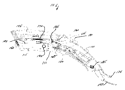
Referring to the figures and, in particular, Fig. 1, there
is shown a hand held steam appliance generally represented by
reference numeral 105.
Appliance 105 has a housing 110 that houses, and preferably
encloses, boiler 115 and pump 120. Housing 10 is adapted to
support a nozzle 150 at one end and is constructed to farm a
- 4 -
CA 02416078 2003-O1-09
884.0094USP
handle at another end. Switch 125 is mounted to housing 110 with
its actuator 130 protruding through an opening in the housing
110. First water pipe 135 conveys water from water tank 145 to
pump 120. Second water pipe 140 conveys water from pump 120 to
boiler 115. Upon entering boiler 115, the water becomes steam
and is expelled from nozzle 150. Cable 155 provides electrical
power for pump 120 and boiler 115.
Water tank 145 is detachable from housing 110. In a
preferred embodiment, water tank 145 is released by operating
release button 160. Upon detachment from housing 110, water tank
145 may be carried to a water source and filled. Water tank 145
may be filled through port 165 that may include valuing to
prevent spillage while water tank 145 is disengaged from housing
110. Water tank 145 may alternatively be filled through another
opening or cap, an example of which is shown as filler cap 170.
Water tank 145 may be transparent or translucent, at least in
part, to allow a user to determine the amount of water present in
water tank 145. After filling, water tank is attached to housing
110 and port 165 engages first water pipe 135.
First water pipe 135 provides a conduit between water tank
145 and pump 120. Pump 120 is an electrical pump and can be a
rotary vane, peristaltic, or any other type of pump suitable for
pumping liquid according to the teachings of the present
invention. Pump 120 operates at a fixed voltage or may be
capable of operating over a number of different voltages. For
- 5 -
CA 02416078 2003-O1-09
884.0094USP
instance, pump 120 may operate only at 115 VAC or may operate
over the full range of voltages provided by different countries,
i.e., a range of about 100 VAC to about 230 VAC.
Cable 155 provides electrical power to housing 110 and, in
particular, to pump 120 through switch 125" Cable 155 may also
have at least one safety device 185 in the form of a fuse,
circuit breaker, thermal cut-off, or any other safety device
appropriate for use in a hand held appliance of this type.
Upon actuation, switch 125 serves to complete a circuit
between pump 120 and cable 155, either directly or indirectly,
for example by use of a relay. Thus, switch 125 causes the
application of electrical power to pump 120. In another
embodiment, switch 125 may be capable of causing a variable
amount of power to be applied to pump 120 depending upon the
amount of actuation by a user. In a preferred embodiment, switch
125 may be locked or fixed in position to cause an amount of
electrical power to be applied constantly to pump 120 without
further actuation by a user.
Second water pipe 140 provides a conduit from pump 120 to
boiler 115. Upon application of power from switch 125, pump 120
pumps water from water tank 145 through first water pipe 135 and
through second water pipe 140 to boiler 115.
Cable 155 also provides electrical power to boiler 115. In
one embodiment, boiler 115 receives electrical power as long as
- 6 -
CA 02416078 2003-O1-09
' - 884.0094USP
cable 155 is plugged into a suitable source of electrical power.
In another embodiment, boiler 115 receives electrical power
through switch 125, and thus may receive variable or constant
power according to the configuration of switch 125. Boiler 115
uses the electrical power to produce heat for converting water to
steam. Boiler 115 may be a ~~flash" boiler, capable of producing
steam almost instantaneously upon the introduction of water from
second water pipe 140. Boiler 115 may also have a safety device
in the form of a thermal cut-off 180 to prevent overheating of
the boiler. Similar to pump 120, boiler 115 may operate at a
fixed voltage (e.g., 115 VAC) or may operate over a number of
different voltages that may be found in different countries
(e. g., about 100 VAC to about 230 VAC).
Steam produced by boiler 115 exits appliance 105 through
nozzle 150. Several attachments may be mounted on appliance 105
to aid in the steaming process or to allow other operations to be
performed on fabric, either separately or as part of the steaming
process.
Figure 2 shows a brush attachment 190 and a lint removing
attachment 195 that may be used individually, together, or in any
combination with the steaming capability of the appliance 105.
Figure 3 shows another embodiment of the hand held appliance
shown as reference numeral 205. Housing 220 has a different
shape but both appliance 205 and housing 220 function in the same
_ 7 _
CA 02416078 2003-O1-09
884.0094USP
manner as appliance 105 and housing 110, :respectively, of Figure
1. The boiler 115 of appliance 205 may be regulated by
thermostatic device 210 to ensure production of steam at a
particular range of temperature arid delivery rate. A temperature
dial 215 may be connected to thermostatic device 210 so that a
user may select a particular steam temperature.
Figure 4 shows an attachment 405 with a brush 410 and lint
remover 415 preferably incorporated into attachment 405.
Appliance 205 also has a sole plate 420 that allows a user
to apply pressure, as well as heat, to the garment or other
fabric item. The sole plate 420 also has nozzle 150. The sole
plate 420 may be made of metal or any other suitable material for
providing an even heat distribution to the garment or fabric.
The present invention having been thus described with
particular reference to the preferred forms thereof, it will be
obvious that various changes and modifications may be made
therein without departing from the spirit of the present
invention.
_ g _