Language selection

Search

Patent 2416225 Summary

Third-party information liability

Some of the information on this Web page has been provided by external sources. The Government of Canada is not responsible for the accuracy, reliability or currency of the information supplied by external sources. Users wishing to rely upon this information should consult directly with the source of the information. Content provided by external sources is not subject to official languages, privacy and accessibility requirements.

Claims and Abstract availability

Any discrepancies in the text and image of the Claims and Abstract are due to differing posting times. Text of the Claims and Abstract are posted:

  • At the time the application is open to public inspection;
  • At the time of issue of the patent (grant).
(12) Patent Application: (11) CA 2416225
(54) English Title: STAIR WALKER
(54) French Title: AMBULATEUR « STAIR WALKER »
Status: Deemed Abandoned and Beyond the Period of Reinstatement - Pending Response to Notice of Disregarded Communication
Bibliographic Data
Abstracts

English Abstract


The Stair Walker will replace a regular handrail when in use. It will assist
stair
users with a safer, more controlled and balanced stair accent or decent. The
Stair Walker
will run the length of a set of stairs on the same degree of decline. A bar
will come out
from the rail on a 90 degree angle and run parallel to ground level. The bar
will be in front
of the user at all times. The bar will rest in lock notches that are
incrementally placed on
the length of the rail. The user will lift the bar out of the lock notch and
move it forward
into another lock notch. Then the user will take the next step towards the bar
while holding
onto it at all times. If the user trips, the bar will help brace their fall.


Claims

Note: Claims are shown in the official language in which they were submitted.

Page 3
Claims
The embodiments of the invention in which and exclusive property or privilege
is claimed
are defined as follows:
1. A stair Walker is made from a lightweight strong metal or metal alloy. Its
length
will vary and can be cut and adapted tp any size set of stairs. The shape of
the rail is
tubular. It will be of a diameter convenient to be used like a regular
handrail by
none stair challenged users. It will be installed into the studs at an
appropriate
height relative to its user and run at the same rate of decline as the steps.
Along the
outside (stair side edge of the hand rail) a sliding groove is located. This
groove
will run the length of the rail and allow the bar/slider combination to run
the length
of the rail. Underneath the groove, lock notches just big enough to house the
safety
bar in the locked position will be in place incrementally, there will be as
many lock
notches in place as the length and structural integrity will allow, as these
are part of
the safety mechanism. The slider will be just smaller than the inside of the
tubular
rail; this will allow the slider/safety bar combination to run the length of
the rail
smoothly and securely. The safety bar part of the slider safety bar
combination will
come out from the rail at a 90 degree angle and when in its locked position in
the
lock notches, it will be parallel to the ground. The safety bar will have a
sufficient
width relative to its user covering a span up to 3 feet in width. The rail
will have a
notch at either end of the rail that will allow the safety bar to rest flat
against the
wall when not in use.
2. As defined in claim 1 where a plastic end will he fitted at the end of the
rail
where the cut was made to custom fit the stair Walker.
3. As defined in claim 1 where the lock notches are concealed within the tube.
4. As defined in claim 1,2,3 where a hand release is used instead of lock
notches so
that when the user clutches the hand control, the bar then will be free to
move into
the next position. When the user releases the hand control the bar will be
locked
securely into position.
5. As defined in claim 1,2,4, where a preset able tension control mechanism is
used for
resistance for fluent accent or decent on the stairs instead of the lock
notch.
6. A slider/safety bar that past the lock notch has 2-90 degree bends in it,
after the first
90 degree bend an adjustment mechanism may be used to adjust the height of the
bar to custom fit the user.
7. A Stair Walker wherein the slider system has adjustable preset stopping
points
based on the depth of the stairs.
s

Page 4
8. A Stair walker as defined in claims 1,4,6 wherein the bar is only large
enough to
accommodate one hand for less challenged stair users.
9. A Stair walker as defined in claim 1,4 wherein there is negative tension on
the bar
so that the user must push the bar down the stairs, on the accent, the
negative
tension created will be used as positive tension aiding them in their accent.

Description

Note: Descriptions are shown in the official language in which they were submitted.


CA 02416225 2003-O1-23
Page l:
I~escrip9>ion
The Stair',l~alker is an innovation of the stair step hatndrail. If a
challenged stair
step user is rewired to support their accent or decent with a hand over hand
motion they
are ut thei:r h~d in an u~baya~~,ed nfiiti~ri< Tire shoulders should 1?e s
~ar~ t~ their ath
p _Y - -- p - - ~ ~ p ._ __)
If they do trip there is little chance that their grip on the rail will stop
their fall.
The Stair V~alker will replace the narmal handrail fc~r those who require aid
with
stair steps. It will be installed at the wane angle and high as that of a
regular handrail.
before the user starts their accent or decent they will lift the bar out of
its resting position
and lock it into place at whatever distance the~T choose in front of them. The
user will hold
the bar while taking a step for_w~rd into tl~~ bari keeping the sh_c~ulder-s
~quar_~ to their path
while improving their balance. 'hhey will repeat this motion until they have
reached the end
of their accent or decent. If the user should trip on their decent, the bar in
its locked
position will help brace their fall.
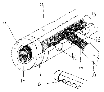
In the following description I will refer the unit that replaces the regular
hand as the rail
(Fig 1a). This is the u.~~it in which will replace tl~e regular haGndrail and
will house the
sliderlbar combination (F ig 1 e). The unit that will be held b;y the user
will be referred to as
the bar (Fig l~. The opening that will allow the bar to slide up and down will
be referred
to as the sliding grocwe (Fi.g l h).. The notches drat run increrner~taHl_y
the length of the rail
will be referred to as the locking notches (Fig lc). The notClaes that avill
allow the bar to
rest flush to the wall when the unit is not in use will be refeured to as the
resting notches
(Fig 1 d).
A Rail will run the length of the stairs on the sane angle of decent. (f'ig 1
a) It will be
mounted ti~rt~~gh the wall and into the studs a the saa~ne revel as the
regular h~~ail it is
replacing. The rail will be tubular in shape and function. The inside of the
rail will be
round in circumference andY~ust large enough to allow the slider to slide
while giving the
Izar stahili_ty<. (Fig i h)
The rail will have a sliding groove at the side running the length of the
rail. (Fig 1b) This
sliding groove will allow the bai to run th.e length of the stairs. The
sliding groove will be
,just large enough to allow the bar slide up and down the rail.
-Underneath the sliding groove tLtere will ~6e Iock notches cul. into the
rail. These cock
notches will run the length of the rail. The notches along with the sliding
groove will be
situated so that vihen the bar is in the -locked position it will -be parallel
to the ground.
There will be as many lock notches on it as functionally possible to allow the
bar to lock at
any position along the way. (Fig 1 c) The Iock notches will be just l~~ge
crieugh to house
the I~ar in the resting position.

CA 02416225 2003-O1-23
1?age ~
The bar will be attached tQ the slider (Fig 1 e) and connect snaking a T
shape. The top of the
T is the slider; it is slightly sn~.aller than its rail housing. This is the
piece that slides up and
dawn the rail while transferring the strength and support from. the. stud
mounted rail to the
bar.
The i_eng. th of_ the T (Fig 1 f~ is tt~_~ 1?~.r an..d will be an
appr~>pr_iate width. reta..tave to the
width of an average. body, it will be used as- to hold onto- or will. brace
their fal.I as the user
makes their accent or decent.
The resting notches will be situated at the eery top and bottom of the rail.
These notcl°les
will allow the bar to rest flat against the wall when it is not in use. (Fig l
d)
The bar will be fitted with end caps that t~lill create the gap for the
resting notch and protect
against -~~tal -shards frc~the eut of wst~m fiatirrg the rail to the -sups ~fi-
g 1 i~
~ foam pad will slide over the l~a~° allowing it to be more easily
gripped. (Fig lg~
Figure 2a shows the Stair Walker in use.

Representative Drawing
A single figure which represents the drawing illustrating the invention.
Administrative Status

2024-08-01:As part of the Next Generation Patents (NGP) transition, the Canadian Patents Database (CPD) now contains a more detailed Event History, which replicates the Event Log of our new back-office solution.

Please note that "Inactive:" events refers to events no longer in use in our new back-office solution.

For a clearer understanding of the status of the application/patent presented on this page, the site Disclaimer , as well as the definitions for Patent , Event History , Maintenance Fee  and Payment History  should be consulted.

Event History

Description Date
Application Not Reinstated by Deadline 2009-01-23
Time Limit for Reversal Expired 2009-01-23
Inactive: Abandon-RFE+Late fee unpaid-Correspondence sent 2008-01-23
Deemed Abandoned - Failure to Respond to Maintenance Fee Notice 2008-01-23
Inactive: Entity size changed 2007-01-23
Revocation of Agent Requirements Determined Compliant 2006-01-12
Inactive: Office letter 2006-01-12
Letter Sent 2006-01-12
Appointment of Agent Requirements Determined Compliant 2006-01-12
Revocation of Agent Request 2005-12-29
Reinstatement Requirements Deemed Compliant for All Abandonment Reasons 2005-12-29
Appointment of Agent Request 2005-12-29
Inactive: Adhoc Request Documented 2005-10-26
Inactive: Adhoc Request Documented 2005-08-11
Deemed Abandoned - Failure to Respond to Maintenance Fee Notice 2005-01-24
Change of Address Requirements Determined Compliant 2004-12-10
Change of Address or Method of Correspondence Request Received 2004-11-22
Inactive: Adhoc Request Documented 2004-11-17
Application Published (Open to Public Inspection) 2004-07-23
Inactive: Cover page published 2004-07-22
Inactive: First IPC assigned 2003-03-05
Inactive: IPC assigned 2003-03-05
Inactive: Office letter 2003-02-25
Inactive: Filing certificate - No RFE (English) 2003-02-18
Filing Requirements Determined Compliant 2003-02-18
Application Received - Regular National 2003-02-18

Abandonment History

Abandonment Date Reason Reinstatement Date
2008-01-23
2005-01-24

Maintenance Fee

The last payment was received on 2007-01-23

Note : If the full payment has not been received on or before the date indicated, a further fee may be required which may be one of the following

  • the reinstatement fee;
  • the late payment fee; or
  • additional fee to reverse deemed expiry.

Please refer to the CIPO Patent Fees web page to see all current fee amounts.

Fee History

Fee Type Anniversary Year Due Date Paid Date
Application fee - small 2003-01-23
MF (application, 3rd anniv.) - small 03 2006-01-23 2005-12-29
Reinstatement 2005-12-29
MF (application, 2nd anniv.) - small 02 2005-01-24 2005-12-29
MF (application, 4th anniv.) - standard 04 2007-01-23 2007-01-23
Owners on Record

Note: Records showing the ownership history in alphabetical order.

Current Owners on Record
CHRIS MANSON
Past Owners on Record
None
Past Owners that do not appear in the "Owners on Record" listing will appear in other documentation within the application.
Documents

To view selected files, please enter reCAPTCHA code :


To view images, click a link in the Document Description column. To download the documents, select one or more checkboxes in the first column and then click the "Download Selected in PDF format (Zip Archive)" or the "Download Selected as Single PDF" button.

List of published and non-published patent-specific documents on the CPD .

If you have any difficulty accessing content, you can call the Client Service Centre at 1-866-997-1936 or send them an e-mail at CIPO Client Service Centre.


Document
Description 
Date
(yyyy-mm-dd) 
Number of pages   Size of Image (KB) 
Abstract 2003-01-23 1 26
Drawings 2003-01-23 2 67
Description 2003-01-23 2 145
Claims 2003-01-23 2 104
Representative drawing 2003-03-06 1 27
Cover Page 2004-06-28 1 52
Filing Certificate (English) 2003-02-18 1 159
Notice: Maintenance Fee Reminder 2004-10-26 1 119
Courtesy - Abandonment Letter (Maintenance Fee) 2005-03-21 1 174
Second Notice: Maintenance Fee Reminder 2005-07-26 1 116
Notice: Maintenance Fee Reminder 2005-10-25 1 118
Notice of Reinstatement 2006-01-12 1 165
Reminder - Request for Examination 2007-09-25 1 127
Courtesy - Abandonment Letter (Request for Examination) 2008-04-16 1 166
Courtesy - Abandonment Letter (Maintenance Fee) 2008-03-19 1 175
Correspondence 2003-02-18 1 9
Correspondence 2004-11-22 1 17
Correspondence 2005-09-08 4 130
Fees 2005-12-29 1 38
Correspondence 2005-12-29 2 64
Correspondence 2006-01-12 1 15
Fees 2007-01-23 1 39