Note: Descriptions are shown in the official language in which they were submitted.
CA 02416618 2003-O1-16
WO 02/11602 PCT/USO1/24818
LOAD LIFTING/LOWERING MECHANISM
Background of the Invention
The present invention relates generally to the
cleaning and decontamination art. It finds particular
application in conjunction with washers for washing
instruments and equipment such as surgical, medical, dental,
veterinary, and mortuary instruments and equipment which
contain, or potentially contain, biological contaminants and
will be described with reference thereto. It is to be
appreciated, however, that the invention will also find
application in conjunction with washing, sanitizing, and
disinfecting equipment of various types.
Medical, dental, surgical, veterinary and
laboratory equipment and instruments have been cleaned
and/or sterilized in a number of different ways, such as by
water/detergent washing, steam, hydrogen peroxide or other
vapor treatments, or reagent treatments. Known under
counter washing systems, for cleaning equipment and
instruments of the foregoing nature, operate much like
household dishwashers and typically include a washing
chamber defined by opposed sidewalls, a rear wall, opposed
upper and lower walls, and a front door. At least one
slidable rack or basket is disposed within the chamber for
carrying the various instruments and/or equipment to be
cleaned.
The front door of known under counter washing
systems is generally pivotally attached to a lower portion
of the front of the washing system and is configured to
CA 02416618 2003-O1-16
WO 02/11602 PCT/USO1/24818
-2-
selectively pivot between a closed vertical position and an
open horizontal position. When the door is in the open
horizontal position, the rack or basket slides out of the
washing chamber on side rails or an upper surface of the
door. Assuming the rack or basket is full, it is unloaded
and then reloaded while being supported by the front surface
of the door. After being loaded, the rack or basket is slid
back in to the washing chamber and the door is pivoted to
the vertical closed position. In this position, the washing
system is sealed and ready for operation.
Although this type of system effectively cleans
and dries a variety of different types of instruments and
equipment, it has some drawbacks, particularly during
loading and unloading operations. For a number of reasons,
some of which are obvious, mounting washing systems under a
standard counter where they are supported by a floor surface
is convenient, efficient, aesthetically pleasing, and
maximizes work surface area. During loading and unloading
of the washer system, the washer door is pivoted to the
horizontal open position where it lies in a horizontal plane
that is relatively close to the floor surface. Thus, the
rack or basket being supported by the top surface of the
pivotable door is located at a low working position which is
difficult for an operator to reach. An operator generally
has to bend over to load and unload the rack or baskets.
This "bent-over" working position may be acceptable
for general household use where an operator is only loading
and unloading the washer a few times a day. However, a
"bent-over" working position can become extremely arduous and
uncomfortable for an operator whose duties include multiple
loadings and unloadings of a washing system throughout the
course of an entire work day. Operators having such duties
are common in the medical, dental, surgical, veterinary and
laboratory fields. Moreover, the loading and unloading of
washing systems in these fields is relatively long when
compared to loading and unloading a traditional household
washer. Such repetitive loading and unloading in the "bent-
CA 02416618 2003-O1-16
WO 02/11602 PCT/USO1/24818
-3-
over" position for extended periods of time is a factor which
may cause or lead to back injuries for operators.
Alternatively or in addition, such activity may lead to back
pain or severe discomfort.
The present invention provides a new and improved
construction which enables a user to load and unload the
washing system in an upright position, thereby overcoming
the above-referenced problems and others.
Summary of the Invention
In accordance with one aspect of the present
invention, a washer is provided. The washer includes a
washing chamber defined by a series of walls and a front
door disposed adjacent a front portion of the washer. The
front door is selectively pivotable between an open position
and a closed position. The washer further includes a
lifting system, coupled to the front door, that moves the
front door in a vertical direction between a first lower
position and a second upper position.
In accordance with another aspect of the present
invention, a method of loading and unloading a washer
includes pivoting a front door of a washer to an open
horizontal position. An article carrying device is slid
from a washer chamber on to an upper surface of the open
front door. The front door is then raised to an upper
position where an operator can load and unload the article
carrying device in an upright and ergonomic position. The
article carrying device is unloaded and reloaded in the
upper position. The front door is then lowered to a lower
position and the article carrying device is slid into the
washing chamber. Finally, the front door is closed.
A first advantage of the present invention is that
it enables an operator to perform loading and unloading
operations in an upright, ergonomic position.
Another advantage of the present invention is that
is lifts loads smoothly.
Yet another advantage resides in reduced operator
CA 02416618 2003-O1-16
WO 02/11602 PCT/USO1/24818
-4-
injuries and muscle strain.
Still further advantages of the present invention
will become apparent to those of ordinary skill in the art
upon reading and understanding the following detailed
description of the preferred embodiment.
Brief Description of the Drawings
The invention may take form in various components
and arrangements of components, and in various steps and
arrangements of steps. The drawings are only for purposes
of illustrating preferred embodiments and are not to be
construed as limiting the invention.-
FIGURE 1A is a perspective view of a washing
device in accordance with the present invention having a
front door that is open and in a lower position;
FIGURE 1B is a perspective view of the washing
device of FIGURE 1A with the front door located in an upper
position;
FIGURE 2 is a side cross sectional view of the
washing device showing the front door in the lower position
and also showing the front door in phantom while in the
upper position;
FIGURE 3A is a side perspective view of a lifting
assembly configured to move the front door between an upper
position and a the lower position;
FIGURE 3B is a perspective view of a motor, two
sprockets and two chains which are used to help drive the
door between the upper and the lower position;
FIGURE 4 is a perspective view of a simplified
version of the washing device in accordance with the present
invention; and
FIGURE 5 is a perspective view of a lifting
assembly for a washing device in accordance with an
alternate embodiment of the present invention.
Detailed Description of the Preferred Invention
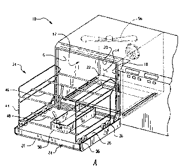
With reference to FIGURES 1A and 1B, a washing
CA 02416618 2003-O1-16
WO 02/11602 PCT/USO1/24818
-5-
device 10 includes a washing chamber 12 defined by a back
wall 14, opposing side-walls 16, 18, opposing top and bottom
walls 20, 22 and a front door 24. The front door 24, which
has an upper surface 26 and a lower surface 28, is
selectively pivotable between a vertical closed position and
a horizontal open position. The walls and door defining the
washing chamber are preferably constructed from stainless
steel. However, it will be appreciated that other
materials, such as high impact plastic materials, may be
used to construct the walls and door.
A rack 34, for carrying articles such as medical
equipment and instruments, is configured to roll in and out
of the washing chamber. The rack is supported by a
plurality of wheels 36 which allows it to be easily rolled
in and out of the washing chamber. It will be appreciated,
however, that the rack may be supported by any other means
such as low coefficient of friction slide blocks. While the
rack is disposed within the washing chamber, the wheels are
supported by a pair of flanged members 40, 42 which extend
horizontally inward from the opposing sidewalls 16, 18
respectfully. When the rack is rolled out of the washing
chamber it is supported by the upper surface 26 of the front
door 24.
The rack preferably includes a frame 44, an upper
shelf 46 and a lower shelf 48. The upper and lower shelves
are each dimensioned to support at least one basket 50 which
carries articles to be cleaned. Rotary spray heads 52, 54,
having a series of nozzles, are rotatably mounted beneath
the upper and lower shelves 46, 48 respectively. Rotary
spray heads 56 on the ceiling and stationary nozzles are
also contemplated. During operation, the spray heads rotate
about a vertical axis and provide cleaning solutions at high
impact velocity to the articles within the washing chamber.
With reference to FIGURE 2, a pump 60 is disposed
below the bottom wall 22 of the washing chamber 12 in order
to provide cleaning solutions, such as water, detergent,
CA 02416618 2003-O1-16
WO 02/11602 PCT/USO1/24818
-6-
etc., to the spray nozzles. To heat the water as it
collects in a sump defined above the bottom wall 22, a
heating source 62, such as a heating coil, is disposed in
the sump. A cleaning dispenser 64 injects detergent,
disinfectants, corrosion inhibitors, and other cleaning
agents into the heated water after the water has exited the
pump. When the rack is slid into the washing chamber, a
fluid sealing connector, provided on a rear portion of the
rack, engages a connection member 66 located on the back
wall 14 of the washing chamber. Thus, the cleaning
solutions travel through connection member 66 and are
directed to the spray heads where the solutions exit through
the nozzle openings. The water, detergent, etc. pass
through a drain 70 associated with the bottom wall of the
washing chamber.
When it is desired to load or unload the washing
device 10, the front door 24 is pivoted to the horizontal
open position and the rack 34 is rolled out on to the upper
surface 26 of the front door. At this position, the door
and rack are located relatively close to the floor surface.
In order to facilitate loading and unloading of
the rack in the present invention, a lifting system 72 (see
FIGURE 3A) selectively moves the front door in the vertical
direction between a first lower position 74 and a second
upper position 76. During loading and unloading of the
washing device, the lifting system mechanically raises the
door and supported rack to the upper position. In the upper
position, the rack is either rolled onto a transfer cart
which is unloaded at a storage cite or unloaded directly.
This enables a user to load and unload the rack while
remaining in an ergonomic upright position. Furthermore,
the potential for operator back injuries, back pain,
discomfort, etc. is reduced. After the rack has been loaded
or unloaded, the door is mechanically moved to the lower
position where the rack can be easily rolled in to the
washing chamber.
With reference to FIGURES 3A and 3B, the
CA 02416618 2003-O1-16
WO 02/11602 PCT/USO1/24818
mechanical lifting system includes a gear motor 80
configured to drive a first chain 82. The first chain
engages a first sprocket 86 that is operatively connected to
a horizontal shaft 88. Sprocket 86 transmits power from the
first chain to the horizontal shaft, thereby rotating the
shaft about its central horizontal axis. The horizontal
shaft extends across the width of the washing device and has
opposing first and second axial ends 94, 96.
In a preferred embodiment, a first series of
components are operatively associated with the first axial
end 94 of the horizontal shaft 88 and a second series of
components are operatively associated with the second axial
end 96 of the horizontal shaft (see FIGURE 4). Both series
of components are driven by the horizontal shaft and are
configured to selectively move the front door between the
lower position and the upper position. The first and second
series of components are disposed on opposite sides of the
washing device 10 and are preferably identical. Thus,
reference will be made only to one series of components,
namely those associated with the first axial end of the
horizontal shaft as shown in FIGURES 3A and 3B.
The first series of components includes a second
sprocket 102 having a plurality of teeth 104 disposed around
its periphery. Sprocket 102 is operatively attached to the
first axial end of the horizontal shaft. A second chain
110, having a first end 112 and a second end 114, engages
sprocket 102. A third chain 116, having a first end 118 and
a second end 120, engages a third free moving sprocket 122
located on an upper side portion of the washing device. The
3 0 first end of chain 110 and the first end of chain 116 are
interconnected by a tension control member 126.
The tension control member preferably includes a
body 128 having an upper end and a lower end. The upper end
of the body has an aperture 136 dimensioned to receive an
upper fastener 138. Similarly, the lower end of the body
includes an aperture 140 dimensioned to receive a lower
fastener 142. The upper and lower fasteners each include a
CA 02416618 2003-O1-16
WO 02/11602 PCT/USO1/24818
_g_
ring 146, 148 located at their free axial end. Ring 146 and
ring 148 are operatively connected to the first end 112 of
the second chain 110 and the first end 118 of the third
chain 116 respectfully. The fasteners may be tightened or
loosened in order to adjust the tension of the chains to a
desired level.
With continued reference to FIGURES 3A and 3B, a
follower 154, which is constrained to a vertical guide 156,
interconnects the second end 114 of chain 110 and the second
end 120 of chain 116. The follower 154 includes a
substantially rectangular body 158 and a block member 160
fastened to a side portion of the rectangular body. The
second end 114 of chain 110 is operatively connected to an
elongated rod 162 extending downwardly from a bottom surface
of block member 160. The second end 120 of chain 116 is
operatively connected to a top surface of block member 160.
The door is pivotably mounted to the block member 160.
A semicircular connecting member 164 extends from
the upper surface 26 of the front door 24 and is slidably
mounted to the rectangular body 158 of the follower. In
addition, a pulley 166 is rotatably mounted to a lower side
surface of the rectangular body. An elongated wire 168,
having a first end 170 attached to a tension spring 172 and
a second end 174 attached to the connecting member 164,
engages the pulley. The wire and tension spring apply a
force to the front door which biases the door toward the
closed partition causing the door to become substantially
weightless. Thus, it is relatively easy for an operator to
pivot the front door in the lowered position to the vertical
closed position. As the door is raised, the spring 172
contracts, reducing or eliminating the biasing force.
As noted above, the second series of components
associated with the second axial end 96 of the horizontal
shaft 88 are identical to the first series of components
associated with the first axial end 94 of the horizontal
shaft.
In operation, the front door 24 is pivoted to the
CA 02416618 2003-O1-16
WO 02/11602 PCT/USO1/24818
-9-
horizontal open position. The rack 34 is rolled out of the
washing chamber 12 on to the upper surface 26 of the front
door. A first push button is pressed which actuates the
gear motor 80. The motor drives the first and second series
of components which raise the door until the follower 154
reaches a set of upper limit switches mounted at the top of
the guide 156 where the front door stops in the upper
position. Assuming the rack is fully loaded, the operator
removes the cleaned articles from the rack and replaces them
with articles which need to be cleaned. This is all done
while the operator is in an upright, ergonomic position.
When unloading and loading is complete, a second push button
is pressed which causes the door to move vertically downward
to the lower position where the follower engages a lower
limit switch. The rack is easily rolled back in to the
washing chamber. The front door is then pivoted to the
vertical closed position so that the washing device is
sealed and ready for another cleaning cycle.
In an alternate embodiment, the horizontal shaft
88 may be configured so that it does not extend across the
entire width of the washing device. In such an embodiment,
only the first series of components are provided for moving
the front door 24 between the upper and lower positions. To
prevent the follower and slide from binding, an upward
biasing force is preferably applied to the side of the front
door opposite the first series of components. Such a force
causes the side of the door opposite the first series of
components to become substantially weightless. The
continuous force is preferably applied by a spring loaded
assembly.
Turning now to FIGURE 5, another alternate
embodiment is shown. In this embodiment, the lifting system
includes a fluid cylinder 180, such as a hydraulic pneumatic
cylinder, which drives the front door 24 between the first
lower position 74 and the second upper position 74. A cable
182, having a first end 184 and a second end 186, is coupled
to the fluid cylinder and engages a series of pulleys
CA 02416618 2003-O1-16
WO 02/11602 PCT/USO1/24818
-10-
arranged at predetermined locations around the washing
device. The cable extends from a first follower 188, to a
first pulley 190, to a second pulley 192, to a third pulley
194, to a fourth pulley 196, to a fifth pulley 198, to a
sixth pulley 200, to a seventh pulley 202, to an eighth
pulley 204, to a ninth pulley 206, and terminates at a
second follower 208. An extendable and retractable arm 210
extends from the fluid cylinder and is operatively connected
to pulley 198.
In operation, the front door is opened to its
horizontal position. Arm 210 of the fluid cylinder is
retracted causing cable 182 to apply a pulling force on the
first and second followers 188, 208. The pulling force
slides the first and second followers vertically upward
along first and second vertical guides 214, 216
respectively. Thus, the front door, which is pivotally
mounted to the first and second followers, is raised to the
upper position where an operator can unload and load an
article carrying assembly in an erect ergonomic position.
When unloading and reloading is complete, the fluid cylinder
extracts the arm which releases the pulling force applied to
the front door. The front door then lowers to the lower
position where the article carrying assembly can be placed
back within the washing chamber 12.