Note: Descriptions are shown in the official language in which they were submitted.
CA 02417111 2003-O1-23
WO 02/10531 PCT/FI01/00684
1
STUD ARRANGEMENT AND METHOD
The present invention relates to a stud system wherein each
respective stud includes mutually attached flanges which form
an essentially monolithic entity, where said flanges are
formed of a wood material so that respective flanges include a
longitudinally extending side portion which has a beveled
cross section and which is directed towards the inside of the
stud. The present invention also relates to a method for manu-
facturing studs or the like generally elongated pieces which
include opposite flanges, which flanges are formed of a wood
material and are glued together in order to constitute a
monolithic entity. Further, the present invention relates to a
method at stud systems including corresponding studs.
Prior art knows different stud systems made of relatively thin
sheet metal, wherein the studs usually are designed to have a
generally U-shaped cross section. Such studs are utilized
especially for frame structures for parti.tional walls and the
like structures, where wall panels based on, e.g., waste wood
or especially gypsum are attached, for example by screwing, to
the flanges of the vertically erected studs. Such studs are
usually attached essentially vertically between corresponding
horizontal studs which are arranged at the floor and the
ceiling, respectively, in a space where the partitional wall
will be erected. Metal studs, however, cause some problems and
drawbacks which have been discussed in more detail elsewhere,
and instead it has been proposed that corresponding studs
could be made of, for example, wood.
One object of the present invention is to provide a stud
system where small dimension wood and such wane edge wood
material also can be utilized, which traditionally cannot be
used~for full value wood products.
Another object is to disclose such a stud arrangement where
CA 02417111 2003-O1-23
WO 02/10531 PCT/FI01/00684
2
the natural properties of wood are used in the best possible
manner and i.e. are utilized in order to keep the stud
straight and without twisting.
A further object is to utilize in an optimal manner the
available wood material and at the same time to provide a stud
system wherein a mutual connection of studs in horizontal and,
respectively, vertical direction is facilitated by the design
of the stud profile, this without, however, a risk for cracks
in the material for this reason.
These and other objects are reached in accordance with the
present invention by means of arrangements and methods having
characteristics which are disclosed in the appended claims.
Especially, the stud system in accordance with the present
invention is characterized in that a side portion at each
respective stud flange is designed as a contact surface for an
intermeshing co-operation with a oorresponding contact surface
at an adjacent flange. Again, the inventive method for manu-
facturing studs is characterized in that the respective stud
flange is designed in form of a first flange strip which in-
cludes a first contact surface which in cross section is
generally toothed and which is arranged in a finger-like inter-
meshing fashion with a second contact surface having a cor-
responding shape and which is located at a second flange strip
which. is designed in a generally corresponding manner.
Further, a method in connection with the stud system is
characterized in that side portions at the respective opposite
flanges are formed to include longitudinally extending tongue
and groove structures, after which respective two opposite
flanges are pressed together in such a way that opposite
tongue and, respectively, groove structures will be positioned
in a mutually intermeshing engagement.
Hereafter some favorable embodiments of the present invention
will be discussed in more detail as examples and with refe-
rence to the appended drawings wherein
CA 02417111 2003-O1-23
WO 02/10531 PCT/FI01/00684
3
Figure 1 generally in section discloses how a timber block for
use as studs in accordance with the present invention
can be taken out also from round timber having a
dimension which is too small for providing full edge
studs of a conventional type,
Figure 2 in a perspective view discloses how material for
studs in accordance with the present.invention can be
formed of the material in wane edge waste wood out-
side boards obtained when heavier timber logs are
sawn,
Figure 3 in section generally discloses the. general principle
of the present invention, as well as a stud profile
in approximately natural size and shaped according to
one embodiment of the present invention,
Figure 4 in the same manner in section discloses a stud
profile according to an especially favorable embodim-
ent of the present invention,
Figure 5 in section discloses how both flange strips at
another especially favorable stud profile according
to a further embodiment of the present invention can
be taken out from a wane edge batten by means of an
especially shaped edge means,
Figure 6 in section discloses how a flange element of a
somewhat heavier type is taken out from a heavier
wane edge plank or from an essentially half-round
timber block,
Figure 7 in section discloses a ready made stud which is com-
posed of flange elements in accordance with Figure 6,
CA 02417111 2003-O1-23
WO 02/10531 PCT/FI01/00684
4
Figure 8 in perspective discloses a portion of a stud in ac-
cordance with Figure 7,
Figure 9 in section discloses an alternative embodiment of the
present invention,
Figure 10 also in section discloses a further stud profile in
accordance with the present invention,
Figure 11 in perspective discloses the general structure of a
stud framing based on studs according to one embodi-
ment of the present invention,
Figure 12 discloses the attachment between a vertical stud and'
a horizontal stud in accordance with a favorable
embodiment of the present invention, in order to
achieve, e.g., a stud framing as disclosed in Figure
12 , and
Figure 13 in more detail discloses the structure and function
of an alternative connector piece for use in ac-
cordance with the embodiment disclosed in Figure 12.
Round timber 1 in accordance with Figure 1 includes an outer
bark layer within which the timber has a generally ring-like
structure based on the yearly growth. Due to this structure
wood material has many good specific properties but also, seen
from a rational building industry viewpoint, a rather un-
practical shape. Thus, a full edge timber block must be sized
taking in account the ,shape of the round timber, which gives
much waste of wood material having equally good mechanical
properties as the full edge timber material, if not in some
cases even better.
In Figure 1 the above fact has been illustrated in such a way
that a full edge timber block referred to as 2a and having a
size which corresponds to the practical maximum size which can
CA 02417111 2003-O1-23
WO 02/10531 PCT/FI01/00684
be taken out from the round timber dimension disclosed has
been indicated in phantom on said round timber block 1. For
the sake of simplicity it is here assumed that said timber
block corresponds to, e.g., a stud dimension of 45x95 milli-
meters which is a common dimension for a stud which is planed
from a 50x100 millimeter raw stud. In Figue 1, as a comparison
to this full edge stud 2a the dimensions for such a full edge
stud referred to as 2 has been indicated in semi-dotted line,
which stud is composed of opposite flanges in accordance with
the present invention and in the same way represents the
maximum size which can be taken out from this same round
timber 1 under utilization of the existing mass of wood.
Further, in the Figure has been indicated under reference 3
the corresponding approximate dimensions for the usable mass
of wood for this specific embodiment, and here the respective
flange strips 4 and 4a have been indicated in semi-dotted line
which together constitute a compound stud 2 in accordance with
the present invention.
The comparison clearly indicates that by means of the present
invention a considerably thicker structurally full edge stud
can be obtained from the same timber 1, which stud has a width
and, respectively, height which normally in relation to cor-
responding measures for a traditional full edge stud 2a is
larger in the order of 15 to 25 o and in some cases even
larger, depending, of course, on the individual shape of the
cross -section. Inversely, this also leads to the advantage
that in order to provide composite studs having the same over-
all dimensions as compact studs one can utilize, in accordance
with the present invention, timber having correspondingly
smaller dimensions. Thus, by means of the present invention
also such a material can be used for structurally important
constructions, which material in accordance with prior art
technology only could be used for secondary purposes or, in
worst case, as firewood. For example, the bending strength for
a stud is to a higher power depending on the dimension of the
wood piece in a direction transverse to the bend, and thus the
CA 02417111 2003-O1-23
WO 02/10531 PCT/FI01/00684
6
material at the full outer edges of a stud has a great
importance for the bending strength. The material close to the
central axis, again, lacks any essential importance for this
strength, For this reason it is clear that such an in-
significant reduction of the stud's functional cross area due
to the groove which extends in the stud clearly is compensated
by the advantages of a stud where the direction of the
material as such provides a better bending strength and where
the stud has better dimensional stability. Further, in fact
this groove can be effectively used for attaching studs in a
manner which earlier has been impossible without special ad-
ditional measures. Thus, a stud in accordance with the present
invention has a clear added value in relation to such full
edge studs which merely have been taken out from the timber
block 1.
Figure 2 discloses another example of how flange material 4,
4a can be taken out from a timber block, in this case a wane
edge plank 5 of a suitable thickness which has been obtained
when a full edge block 2a has been sawn out from round timber
1.
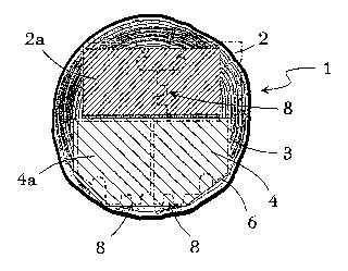
Figure 3 discloses an example of a stud 2 in ' accordance with
one embodiment of the present invention. This stud includes
two opposite flanges 4, 4a having one respective side which is
essentially straight while a second side portion shows a
profile which includes i.a. a bevelled inner edge 6 and 6a,
respectively, between which edges is formed a generally wedge-
shaped groove 7 which i.a. can be utilized for the attachment
of the stud 2 as will be described in more detail below. Said
flanges 4, 4a are mutually directly interconnected along a
contact surface 8. In accordance with the present invention
this contact surface 8 includes a profiling 9 which is general-
ly toothed in cross section and, respectively, has a tongue-
and-groove structure in the longitudinal direction so that the
profiles at respective opposite flanges 4, 4a can be brought
into a close mutual intermeshing relationship. Figure 3
CA 02417111 2003-O1-23
WO 02/10531 PCT/FI01/00684
7
further discloses that the respective co-operating flange
strip 4, 4a favorably is designed as piece which in cross
section is slantingly but otherwise essentially rectangular
and in some cases square, so that said contact surface 8 is
formed at a side which is adjacent to the tapered side 6, 6a.
Thus, at a stud in accordance with the present invention said
profiling 9 includes generally tongue- and, respectively,
groove-like formations which extend in the stud's longitudinal
direction. At both flanges 4, 4a said formations include
favorably at least 3 co-operating opposite engagement surfaces
10, 10' and 10", favorably so that said intermeshing surfaces
are designed, in practice, to mutually interlock by means of
the friction between the opposite surfaces. Favorably, said
co-operating surfaces 10, 10', 10" are slightly inclined so
that an angle cx is in the order of 5° to 15°, favorably about
7°, between the surface planes and a plane which is transverse
in relation to the general extent of the contact surface and
extends in the longitudinal direction of the stud. Thus, in
the embodiment disclosed in Figure 3 the profiling 9 at each
respective flange~4, 4a comprises essentially planar slightly
inclined engagement surfaces 10, 10', 10" which in cross
section are arranged conically, but also other types of self-
locking surface formations can be imagined within the in-
ventive idea.
According to a favorable embodiment of the present invention
two such opposite flange pieces 4, 4a are interconnected by
pressing the tongue-and-groove formations 9 of said contact
surfaces 8 so that a locking is obtained between co-operating
sides surfaces 10, 10', 10" of the tongues and the grooves. A
glue is favorably provided at one or both surfaces, which glue
connects the~flanges 4, 4a to a monolithic entity, i.e. the
stud 2. At the same time the glue favorably acts as a
lubricating means which facilitates the pressing together of
the flanges 4, 4a. Favorably, the contact surfaces 8 of the
flanges are arranged in such a way that a sufficient locking
CA 02417111 2003-O1-23
WO 02/10531 PCT/FI01/00684
8
between said surfaces 8 takes place already during the pres-
sing so that the glue's consolidation can take place at a
later stage, for example at its own pace after the studs 2
have been packed. Such a design facilitates a high manu-
facturing speed.
Due to the co-operation between the three self-locking inter-
meshing surfaces 10, 10', 10" the stud 2 itself maintains the
straight shape into which it is forced during the compression
of the flanges 4, 4a. The flange material is favorably consti-
tuted by opposite portions of the same round timber 1 or wane
edge block 5, and in this manner any inherent bending tendency
of the wood material in one flange 4 is~compensated by the
fact that the opposite co-operating flange 4a has an inherent
bending tendency which is directed in the opposite direction.
This stability in shape is achieved due to the co-operating
intermeshing surface's three-dimensional character usually in
both transverse directions of the stud. By means of an arrange-
ment in accordance with the present invention the co-operating
glue surfaces will be large, usually about 500 larger than for
such planar contact surfaces which normally are used when
strip-like wooden pieces are glued together, and this also
increases the breaking strength.
Figure 4 discloses an especially favorable embodiment of the
present invention, wherein the generally wedge-like groove 7
between the inclined flange surfaces 6, 6a has been supple-
mented with an additional groove 11 which extends in the longi-
tudinal direction of the stud and essentially at the bottom of
said groove 7. This additional groove 11, which is the object
of a parallel patent application, extends in said groove 7
laterally into the flange material 4, 4a, and thus the inter-
section between said groove 11 and the essentially planar
bevelled flange inner side 6, 6a constitutes a retaining edge
12 having a function which will be discussed later on.
Figure 5 discloses how two respective co-operating flanges 4,
CA 02417111 2003-O1-23
WO 02/10531 PCT/FI01/00684
9
4a by means of one or several specifically designed cutter
blades 12 is suitably planed or milled from, e.g., a half-
round basic material 5. By means of the active shape of the
blade 12 the profiling 9 for the flange's 4, 4a respective
contact surfaces 8, 8a are shaped so that they mutually co-
operate to form a monolithic entity. The Figure also discloses
the fact that the flange strips 4, 4a according to the present
invention favorably have an asymmetrical design which, again,
provides a symmetrical end product.
By means of a carefully balanced design of the tongue-and-
groove profiling 9 the wood material available in round timber
1 of different dimensions can be optimally'utilized. Tn Figure
1 it can be observed that 'the useful wood material which is
referred to as 3 in fact, for the profile disclosed, is not
quite centered in relation to the cross surface area of the
round timber 1. Tn an according manner it sometimes is ap-
propriate to make the tongue-and-groove profiling 9 at op-
posite sides of the wood material 3 instead of at the same
side as disclosed, e.g., in Figure S. For certain profile
designs the optimal profiling may be evenly distributed along
the circumference of the round timber 1 so that each side of
the timber is machined in order to form a straight flange edge
~13, an slantingly profiled flange side 6, 6a and a toothed
contact surface 9. Figure 6 discloses such an arrangement and
further that flange strips 4, 4a for studs 2 in accordance
with the present invention can be formed of both naturally
rounded wood material 3a and of a wood material 3 which, for
example, has been provided by splitting wane edge wood
material.
In Figure 7 an example is disclosed in cross section of how a
common stud of standard dimensions has been achieved by a
profiling as disclosed in Figure 6, and Figure 8 discloses, as
a perspective view, a section of the same stud, showing how
the longitudinal groove 7 and the additional groove 11 run in
the stud's 2. whole length. Usually it is appropriate to
CA 02417111 2003-O1-23
WO 02/10531 PCT/FI01/00684
directly give the stud its final dimensions, but in some cases
it may be of advantage to primarily dimension the studs to
include, at least in one direction, a slightly larger
dimension than the final one, in which case the stud, e.g.,
after the gluing is machined to obtain the final desired
dimensions.
Figures 9 and 10 disclose examples of alternative embodiments
of the present invention, wherein the stud flange profiles 4,
4a include a generally toothed contact surface without the
planar intermediate surfaces 14 which are typical for the
other embodiments, see for example Figure 6, and which extend.
between the co-operating intermeshing surfaces 10, 10', 10"
generally parallel to one flange surface. Again, Figure 10
discloses a stud profile having two opposite grooves 7, 7a
and, respectively, two opposite additional grooves 11, 11a.
Figure 11 generally discloses how a stud structure such as the
framework for a partitional wall or the like is built up of
studs 2 in accordance with the present invention. Here, the
stud structure suitably includes generally vertical studs 2b
which at their ends are attached to horizontal studs 2c which
usually, but not always, are attached to the floor and the
ceiling, respectively, in the space where the partitional wall
will be erected. The Figure discloses a connection including
special connector pieces or elements 15 which are generally
wedge-shaped in two directions and which co-operate with said
grooves 7 in said vertical and said horizontal studs 2b and
2c, respectively. These co-operating wedge-shaped connector
pieces 15 are nailed, glued or attached in some other manner
in the respective groove and they prevent said studs 2b from
displacement when wall boards 16 made of gypsum or the like
are attached on said stud, usually by screwing them to the
stud flanges 4, 4a.
Figures 12 and 13 disclose an alternative attachment method
which utilizes the additional groove 11 which has been
CA 02417111 2003-O1-23
WO 02/10531 PCT/FI01/00684
11
mentioned above. In this embodiment a specially designed
separate connector element 15 is utilized, which element
extends in said additional groove 11 in a first stud 2a and
which, for example, by striking or turning is introduced so
that one end 17 and/or edge 18 of said connector element 15
will be positioned in said additional groove 11 in a second
stud 2c, suitably behind said retaining edge 12. Tn some cases
the introduction includes that said end 17 and/or a portion of
said retaining edge 12 will be slightly deformed. By means of
this arrangement a very rigid connection is achieved between
vertical and horizontal studs 2b and 2c, respectively, while
at the same time the connection with respect to its nature is
such that the horizontal position of the vertical studs 2b can
be adjusted to some extent at a later stage by repositioning
the stud in a lateral direction. In some embodiments the at-
tachment arrangement disclosed renders possible that studs 2b
are detached also after the attachment.
Further, in some embodiments said connector element 15 can be
used for attaching studs to each other in a parallel dis-
position and/or for attaching details such as electrical
boxes, door frames and the like (not shown) to said studs 2,
2b, 2c. Here Figure 13 discloses an example of an appropriate=
1y designed connector element 15 which includes both a longi-
tudinally extending profiling 19 of an edge 18 which is
favorably arranged for continuous intermeshing in the groove
in a first stud 2b, as well as an end profiling 20 for a cor-
responding intermeshing into a transverse second stud 2c (not
shown in the Figure). Since said connector element 15
favorably is double-sided and comprises two essentially
identically shaped edges 18 it can also be used for attaching
studs 2b in a parallel manner as generally disclosed in Figure
13 .
Above some favorable embodiments of the present invention has
been described with reference to certain examples, but for the
professional it is clear that the invention is applicable. also
in many other ways within the scope of the appended claims.