Language selection

Search

Patent 2417292 Summary

Third-party information liability

Some of the information on this Web page has been provided by external sources. The Government of Canada is not responsible for the accuracy, reliability or currency of the information supplied by external sources. Users wishing to rely upon this information should consult directly with the source of the information. Content provided by external sources is not subject to official languages, privacy and accessibility requirements.

Claims and Abstract availability

Any discrepancies in the text and image of the Claims and Abstract are due to differing posting times. Text of the Claims and Abstract are posted:

  • At the time the application is open to public inspection;
  • At the time of issue of the patent (grant).
(12) Patent Application: (11) CA 2417292
(54) English Title: CIRCULAR SAW HEAD
(54) French Title: TETE DE SCIE CIRCULAIRE
Status: Deemed Abandoned and Beyond the Period of Reinstatement - Pending Response to Notice of Disregarded Communication
Bibliographic Data
(51) International Patent Classification (IPC):
  • A01G 03/04 (2006.01)
  • A01G 03/08 (2006.01)
(72) Inventors :
  • HALVORSON, DAVID J. (United States of America)
  • ANDERSON, TRAVIS A. (United States of America)
(73) Owners :
  • ALAMO GROUP INC.
(71) Applicants :
  • ALAMO GROUP INC. (United States of America)
(74) Agent: FINLAYSON & SINGLEHURST
(74) Associate agent:
(45) Issued:
(86) PCT Filing Date: 2001-02-20
(87) Open to Public Inspection: 2002-02-14
Availability of licence: N/A
Dedicated to the Public: N/A
(25) Language of filing: English

Patent Cooperation Treaty (PCT): Yes
(86) PCT Filing Number: PCT/US2001/040166
(87) International Publication Number: US2001040166
(85) National Entry: 2003-01-28

(30) Application Priority Data:
Application No. Country/Territory Date
09/633,706 (United States of America) 2000-08-07

Abstracts

English Abstract


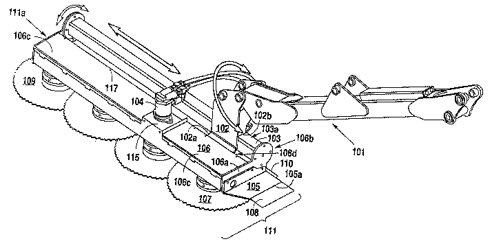
A circular saw head for use as a boom mounted head (111) attachment is
disclosed for agricultural trimming. The blades (107) can cut as much as four
inches of material. An adjustable head piece is provided that is also
reversible allowing for exposure of more or less of the blades. Safety aprons
(108, 110) are provided to deflect cut material away from the operator.


French Abstract

L'invention concerne une tête de scie circulaire destinée à être utilisée comme tête montée en bout de flèche (111) pour l'ébranchage lié à l'agriculture. Les lames (107) peuvent couper une épaisseur de matière allant jusqu'à quatre pieds. Un élément de tête ajustable réversible est prévu pour augmenter ou diminuer le nombre des lames exposées. En outre, des tabliers de sécurité (108, 110) sont prévus pour dévier les projections de matière par rapport à l'utilisateur.

Claims

Note: Claims are shown in the official language in which they were submitted.


5
CLAIMS
1. An agricultural trimming apparatus for use in trimming vegetation and for
use on
a tractor or the like comprising:
a boom arm attached to said tractor;
a boom head attached to said boom arm;
at least one circular saw blade rotatably mounted to said boom head;
a driving means housed within said boom head for driving said circular saw
blade;
a power source mounted to said boom head for engaging said driving means; and
a shielding means attached to said boom head, wherein said shielding means is
positioned so as to deflect cut vegetation away from an operator when said
circular saw
blade is engaged into said vegetation.
2. The agricultural trimming apparatus of Claim 1 wherein said at least one
circular
saw blade further comprises a plurality of circular saw blades rotatably
mounted to said
boom head and driven by said driving means.
3. The agricultural trimming apparatus of Claim 2 wherein said circular saw
blades
can cut as much as four inches of said vegetation.
4. The agricultural trimming apparatus of Claim 3 wherein said circular saw
blades
are in a substantially staggered and overlapped relationship.
5. The agricultural trimming apparatus of Claim 4 wherein said power source is
a
hydraulic motor.
6. The agricultural trimming apparatus of Claim 5 wherein said circular saw
blades
are 26 inches in diameter.
7. The agricultural trimming apparatus of Claim 6 wherein said circular saw
blades
are at least 3/16 inches thick.
8. The agricultural trimming apparatus of Claim 7 wherein said shielding means
is
positioned 45 degrees downward from said boom head.
9. The agricultural trimming apparatus of Claim 8 further comprising a bumper
means attached to said boom head to keep said circular saw blades off the
ground when
said apparatus is in certain positions.

6
10. The agricultural trimming apparatus of Claim 9 wherein said boom head is
reversible.

Description

Note: Descriptions are shown in the official language in which they were submitted.


CA 02417292 2003-O1-28
WO 02/11522 PCT/USO1/40166
1
Title: CIRCULAR SAW HEAD
Inventor: DAVID J. HALVORSON AND TRAVIS A. ANDERSON
1. FIELD OF THE INVENTION
Applicant's invention relates to a circular saw head for cutting tree limbs
which
can be used as a boom mounted head attaclltnent.
BACKGROUND INFORMATION
Agricultlual trimming devices which attach to tractors are usefill in groves
and
orchards, particularly when high trimming of trees is desired. The present
invention is
an agricultural tri1111ning device, more particularly a circular saw head,
that can be
utilized as a boom head attachment for tractors used for right of way
maintenance. The
circular saw head itself has all outer blade that is exposed to reach limbs
better. The
blades are preferably 3/1~ inch thicl~ and 26 inches in diameter. The blades
can cut as
much as four inches of material. The head can also be reversible. Aprons are
provided
at a 45 degree angle to help deflect cut material down toward the ground and
away from
the operator. The blades are offset with overlap by the blades. This results
in a clean cut
with a manicured chainsaw look and fairly rapid production rate. This also
provides a
much safer blade system because the residue from the cutting process is
relatively small.
Applicant knows of no other circular saw head that incorporates the benefits
of
Applicant's invention. U.S. Patent No. 3,138,911 issued to Pounds discloses a
hedge
t11n1111eT fOr attaClll11e11t t0 a traCtOr. However, Applicant's 111Ve11t1011
15 a111111prOVe111e11t
over this previous invention because it incorporates protective shielding
aprons. U.S.
Patent No. 4,815,263 issued to Hartlulg et al discloses an airborne tree
trimmer apparatus
and U.S. Patent No. 5,501,257 issued to Hiclunan discloses a tree trimming
apparatus.
While these inventions have the same intent as the present invention, they are
not related
to the present invention.

CA 02417292 2003-O1-28
WO 02/11522 PCT/USO1/40166
2
SUMMARY OF THE INVENTION
It is an object of the present invention to provide a novel circular saw head
that
produces a clean cut.
It is another object of the present invention to provide a novel circular saw
head
that has a fairly rapid production rate.
Yet another obj ect of the present invention is to provide a novel cir cular
saw head
that is safer.
Still another obj ect of the present invention is to provide a novel circular
saw head
that produces relatively small thrown objects.
It is yet another object of the present invention to provide a novel circular
saw
head that incorporates a shielding means to deflect cut materials away from
the operator
when the circular saw is engaged into vegetation.
It is still another object of the present invention to provide a novel
circular saw
head that can cut as much as four inches of vegetation.
Another object of the present invention is to provide a novel circular saw
head
that incorporates a bumper means to keep the blades off the ground when the
head is in
certain positions.
It is yet another object of the present invention to provide a novel circular
saw
head that is reversible.
In satisfaction of these and related objectives, Applicant's present invention
provides a circular saw head for cutting tree limbs which can be used as a
boom mounted
head attachment.
BRIEF DESCRIPTION OF THE DRAWINGS
Fig. 1 is a perspective view of the preferred embodiment as it would be used.
Fig. 2 is a perspective view of the preferred embodiment.
Fig. 3 is an exploded perspective view of the preferred embodiment.
DETAILED DESCRIPTION OF THE PREFERRED EMBODIMENT
Referring to Fig. 1, a perspective view of the preferred embodiment as it
would
be used is shown. A tractor with an outer boom arm 101 is shown attached to a
boom
head 111 containing circular saw blades 107.
In Fig. 2, a perspective view of the preferred embodiment is shown. The boom

CA 02417292 2003-O1-28
WO 02/11522 PCT/USO1/40166
3
head 111 is attached to a hitch post 102. The hitch post 102 is pivotally
corrected to the
outer boom arm 101. An outer view of the boom head 111 shows a blade saw body
106
which houses at least one, preferably four, circular saw blades 107. The outer
blade 109
is exposed so that it can reach a limb or other similar material on the
outside end l I1a
of the boom head 111. In addition, the blades 107 are offset to allow for
overlap which
creates a constant cutting surface. It is prefeiTed that the blades 107 be
3/1~ inch thick and
have a 26 inch diameter, but obvious modifications can be made to accommodate
the
specific use of the circular saw head. Any type of blade which imparts only a
small
amount or no recoil upon engaging a big load can be used. Chainsaw type blades
or
titanium carbide tipped blades can be used.
The back 106d of the blade saw body 106 acts as an anchor for a first
attaclnnent
point 102a of the hitch post 102 and a top 103a of a tube 103 acts as a second
attachment
point 102b for the hitch post 102. The second attachment point _102b at the
tube 103 can
be pitched forward slightly. With additional holes, the tube 103 can be
pitched at any
desired angle.
There is a guard 105 at the side 106a of the blade saw body 106. Attached at
the
outer edge lOSa of the guard 105 is a first apron 108. The guard 105 and first
apron 108
can act as bumpers to keep the blades 107 out of the ground when the boom head
111 is
in a certain position. A second apron 110 positioned at the rear _106b of the
blade saw
body I06 helps to deflect Cllt materials down rather than towards their
original location.
The angle of the second apron 110 is preferably 45 degrees downwards from the
base of
the rear 106b of the blade saw body 106; however any angle that helps to
deflect the cut
material can be used.
A hydraulic motor 104 is anchored above the blade saw body 106 on a motor
mount plate 1 I5, preferably centrally anchored, in the middle of a two piece
belt cover
106c and serves as the power source to turn the blades 107. The belt cover
106c is held
in place by quick release retainers with studs 117 and quick release receivers
118 (See
Fig. 3).
Fig. 3 is an exploded perspective view of the preferred embodiment. Under the
belt cover 106c, there is a belt 133 system that drives each individual
spindle assembly
125. The blades 107 (See Fig. 2) are mounted to the spindle assembly 125.

CA 02417292 2003-O1-28
WO 02/11522 PCT/USO1/40166
4
More specifically, the blades 107 (See Fig. 2) are secured to the spindle
assembly
125 with an end cap 112. A blade spacer 113 is inserted on the spindle
assemblies 125
of alternating blades 107 (See Fig. 2). For example, in a mower head with four
blades,
the spacers would be placed on the spindle assemblies of blades 1 and 3. This
allows for
the blades 107 (See Fig. 2) to overlap to provide for a better cut when
operating. At the
uppermost portion of the spindle assembly 125 is a hub assembly 116.
There are slots (not shown) in a main channel 122 of the blade saw body 106
tluough which studs 124 on the spindle assembly 125 fit. A plate 123 attaches
to the
main channel 122 and has holes 131 which fit over the studs 124. Tension
adjustment
brackets 129 are placed on the plate 123. A tensioning bolt 132 on the side of
the tension
adjustment brackets 129 is used when the belt 133 system is in place to pull
the belt 133,
preferably a poly-v-belt, tight. The poly-v-belt is preferred in the present
invention
because it has a very small v-groove in the belt itself.
The hydraulic motor 104 more specifically the shaft 104a, is directly coupled
to
a pulley 114 through a flexible coupling 127 and bushing 119. Rubber grommets
128
contribute to the coupling's 127 flexibility.
While the preferred embodiments have discussed the present invention as it
would
be attached to different booms, the present invention could be used in other
types of
heads such as rotaries, flails, or needs associate with sickle bar mowers.
Although the invention has been described with reference to specific
embodiments, this description is not meant to be construed in a limited sense.
Various
modifications of the disclosed embodiments, as well as alternative embodiments
of the
inventions will become apparent to persons slcilled in the art upon the
reference to the
description of the invention. It is, therefore, contemplated that the appended
claims will
cover such modifications that fall within the scope of the invention.

Representative Drawing
A single figure which represents the drawing illustrating the invention.
Administrative Status

2024-08-01:As part of the Next Generation Patents (NGP) transition, the Canadian Patents Database (CPD) now contains a more detailed Event History, which replicates the Event Log of our new back-office solution.

Please note that "Inactive:" events refers to events no longer in use in our new back-office solution.

For a clearer understanding of the status of the application/patent presented on this page, the site Disclaimer , as well as the definitions for Patent , Event History , Maintenance Fee  and Payment History  should be consulted.

Event History

Description Date
Inactive: IPC from MCD 2006-03-12
Application Not Reinstated by Deadline 2005-02-21
Time Limit for Reversal Expired 2005-02-21
Inactive: Status info is complete as of Log entry date 2004-06-22
Inactive: Abandoned - No reply to Office letter 2004-04-29
Deemed Abandoned - Failure to Respond to Maintenance Fee Notice 2004-02-20
Inactive: IPRP received 2003-09-22
Inactive: Courtesy letter - Evidence 2003-03-25
Inactive: Cover page published 2003-03-20
Inactive: Notice - National entry - No RFE 2003-03-18
Application Received - PCT 2003-02-26
National Entry Requirements Determined Compliant 2003-01-28
Application Published (Open to Public Inspection) 2002-02-14

Abandonment History

Abandonment Date Reason Reinstatement Date
2004-02-20

Maintenance Fee

The last payment was received on 2003-01-28

Note : If the full payment has not been received on or before the date indicated, a further fee may be required which may be one of the following

  • the reinstatement fee;
  • the late payment fee; or
  • additional fee to reverse deemed expiry.

Patent fees are adjusted on the 1st of January every year. The amounts above are the current amounts if received by December 31 of the current year.
Please refer to the CIPO Patent Fees web page to see all current fee amounts.

Fee History

Fee Type Anniversary Year Due Date Paid Date
Basic national fee - standard 2003-01-28
MF (application, 2nd anniv.) - standard 02 2003-02-20 2003-01-28
Owners on Record

Note: Records showing the ownership history in alphabetical order.

Current Owners on Record
ALAMO GROUP INC.
Past Owners on Record
DAVID J. HALVORSON
TRAVIS A. ANDERSON
Past Owners that do not appear in the "Owners on Record" listing will appear in other documentation within the application.
Documents

To view selected files, please enter reCAPTCHA code :


To view images, click a link in the Document Description column (Temporarily unavailable). To download the documents, select one or more checkboxes in the first column and then click the "Download Selected in PDF format (Zip Archive)" or the "Download Selected as Single PDF" button.

List of published and non-published patent-specific documents on the CPD .

If you have any difficulty accessing content, you can call the Client Service Centre at 1-866-997-1936 or send them an e-mail at CIPO Client Service Centre.

({010=All Documents, 020=As Filed, 030=As Open to Public Inspection, 040=At Issuance, 050=Examination, 060=Incoming Correspondence, 070=Miscellaneous, 080=Outgoing Correspondence, 090=Payment})


Document
Description 
Date
(yyyy-mm-dd) 
Number of pages   Size of Image (KB) 
Representative drawing 2003-01-27 1 27
Abstract 2003-01-27 1 49
Claims 2003-01-27 2 50
Description 2003-01-27 4 202
Drawings 2003-01-27 3 82
Notice of National Entry 2003-03-17 1 200
Request for evidence or missing transfer 2004-01-28 1 103
Courtesy - Abandonment Letter (Maintenance Fee) 2004-04-18 1 175
Courtesy - Abandonment Letter (Office letter) 2004-06-09 1 167
PCT 2003-01-27 4 114
Correspondence 2003-03-17 1 24
PCT 2003-01-28 3 149