Language selection

Search

Patent 2417543 Summary

Third-party information liability

Some of the information on this Web page has been provided by external sources. The Government of Canada is not responsible for the accuracy, reliability or currency of the information supplied by external sources. Users wishing to rely upon this information should consult directly with the source of the information. Content provided by external sources is not subject to official languages, privacy and accessibility requirements.

Claims and Abstract availability

Any discrepancies in the text and image of the Claims and Abstract are due to differing posting times. Text of the Claims and Abstract are posted:

  • At the time the application is open to public inspection;
  • At the time of issue of the patent (grant).
(12) Patent Application: (11) CA 2417543
(54) English Title: REVOLUTIONARY CANNON
(54) French Title: CANON REVOLUTIONNAIRE
Status: Dead
Bibliographic Data
Abstracts

Sorry, the abstracts for patent document number 2417543 were not found.

Claims

Note: Claims are shown in the official language in which they were submitted.
Sorry, the claims for patent document number 2417543 were not found.
Text is not available for all patent documents. The current dates of coverage are on the Currency of Information  page

Description

Note: Descriptions are shown in the official language in which they were submitted.


CA 02417543 2003-O1-30
Description.
Internal combustion engine with two crank
shafts and two pistons in one cylinder.
At the beginning, when the reciprocating internal combustion engine was
invented
and developed, the fuel economy (diesel and petroleum) - wasn't live issue.
While
engineering continued to develop, the main attention was attended to engine
power,
where was improved fuel mix, spraying of fuel and etc.
Now, when the quantity of the cars, planes, ships, locomotives, agricultural
technics and any technics, using reciprocating internal combustion engine in
each field of
industry, hardly multiplied, the problem of fuel economy and engine power
increase with
the same fuel expense, became urgent.
The basic idea of how reciprocating internal combustion works can give us
device
commonly known as potato cannon. This example explained and could be found at
http://www.howstuffworks.com/engine.htm/printable.
Say that you took a big piece of plastic sewer pipe and put a cap on the end
of it.
Then you sprayed a little WD-40 into the pipe or put in a tiny drop of
gasoline. 'Then you
stuffed a potato down the pipe. When you introduce a spark, you can ignite the
fuel.
The potato cannon uses the basic principle behind any reciprocating internal
combustion
engine: if you put a tiny amount of high energy fuel (like gasoline) in a
small, enclosed
space and ignite it, an incredible amount of energy is released in the form of
expanding
gas.
The best example is an old Revolutionary War cannon (we load the cannon with
the
gun powder and a cannon ball and light it) - that is internal combustion.
If you can create a circle that allows you to set off explosions like this
hundreds of times
per minute and, if you can harness that energy in a useful way, what you have
is the core
of a car engine.
Almost all cars currently use what is called four-stroke combustion circle to
convert
gasoline into motion:
- intake stroke;
compression stroke;
combustion stroke;
exhaust stroke.
Principle of how reciprocating internal combustion engine works (on petroleum
and
diesel) we explained on example of shooting cannon, where in use only the
energy,
released from the ball's shot, flying straight ahead. But there is no use for
kick-energy of
cannon itself, which is equality to energy of cannon's ball.
Due to above-mentioned, our idea of improvement of reciprocating internal
combustion engine consist in more efficient energy using, that allow us to
increase engine
power in two times with the same fuel expense. For using of kick-energy we
suggest to
use two crank shafts in engine and two pistons in each cylinder.
In enclosed bulb - the pressure at each side of it dispart evenly (as known
from
physics).

CA 02417543 2003-O1-30
It could fmd use in two- and four-stroke, petroleum and diesel reciprocating
internal
combustion engines.
If we would consider two- or four-stroke reciprocating internal combustion
engine,
working on petroleum or diesel, than the engine we're suggesting work by the
same
principle, like currently using.
In applying drawings we didn't identify spark plug and injector.
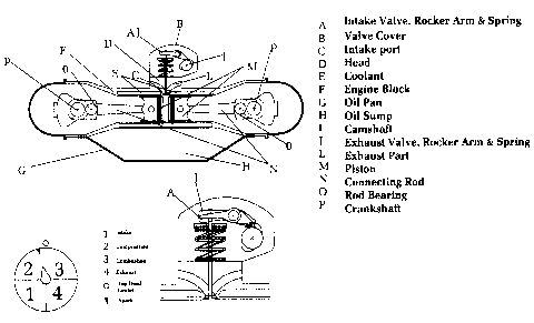
Let's review in one engine 2 crank shafts and in one cylinder -2 pistons,
which
move up and down, as shown in the Figure I and Figure 9/l.
1 Cycle (compression)
Figure l: Two pistons compresses fuel, moves to each other with close valves
intake and exhaust. When pistons reach the point 5-10% before the top dead
center,
the spark plug emits spark to ignite the gasoline.
2 Cycle (combustion)
Figure 2: After pistons hits the top dead center, the gasoline explodes (gases
expand in capacity many times), and it create the pressure inside the
cylinder, which
driving the pistons down (pressing on both pistons evenly). Pistons push both
crank
shafts with evenly energy and make it to rotate. Valves intake and exhaust
still close
until pistons will reach bottom dead center.
3 Cycle (exhaust)
Figure 4: After pistons hits bottom dead center of crank shafts, the exhaust
valves
opens, intake valves still close and let out exhaust, till pistons will reach
top dead
center.
4 Cycle (intake)
Figure 6: After pistons hits top dead center - the exhaust valves will close
and
intake valves will open. Next goes the intake cycle of new charge of gasoline,
till
pistons reach the bottom dead center.
Now engine will go through all these cycles again consistency.
Figure 9: Pay-load goes on flywheel with assistance of crank shaft's
cogwheels.
This pay-load could be use the same way at the currently using engines.
Figure 9/l: Describes parts of engine.
Figure 10: If we would follow our idea: valves - intake and exhaust - possible
to
place not only in the center, but also around the cylinder and in any
cylinder's point.

Representative Drawing
A single figure which represents the drawing illustrating the invention.
Administrative Status

For a clearer understanding of the status of the application/patent presented on this page, the site Disclaimer , as well as the definitions for Patent , Administrative Status , Maintenance Fee  and Payment History  should be consulted.

Administrative Status

Title Date
Forecasted Issue Date Unavailable
(22) Filed 2003-01-30
(41) Open to Public Inspection 2004-07-30
Dead Application 2005-08-25

Abandonment History

Abandonment Date Reason Reinstatement Date
2004-08-25 FAILURE TO COMPLETE

Payment History

Fee Type Anniversary Year Due Date Amount Paid Paid Date
Application Fee $150.00 2003-01-30
Maintenance Fee - Application - New Act 2 2005-01-31 $50.00 2004-12-13
Owners on Record

Note: Records showing the ownership history in alphabetical order.

Current Owners on Record
TIKHOVSKIY, NIKOLAY
Past Owners on Record
None
Past Owners that do not appear in the "Owners on Record" listing will appear in other documentation within the application.
Documents

To view selected files, please enter reCAPTCHA code :


To view images, click a link in the Document Description column. To download the documents, select one or more checkboxes in the first column and then click the "Download Selected in PDF format (Zip Archive)" or the "Download Selected as Single PDF" button.

List of published and non-published patent-specific documents on the CPD .

If you have any difficulty accessing content, you can call the Client Service Centre at 1-866-997-1936 or send them an e-mail at CIPO Client Service Centre.


Document
Description 
Date
(yyyy-mm-dd) 
Number of pages   Size of Image (KB) 
Description 2003-01-30 2 114
Drawings 2003-01-30 7 115
Representative Drawing 2003-03-18 1 16
Cover Page 2004-07-09 1 31
Abstract 2004-07-30 1 1
Claims 2004-07-30 1 1
Correspondence 2003-02-27 1 28
Assignment 2003-01-30 2 78
Correspondence 2004-05-25 1 17
Fees 2004-12-13 1 91