Note: Descriptions are shown in the official language in which they were submitted.
CA 02417746 2003-O1-30
VALVE AND METHOD FOR CASING
DRILLING WITH PRESSURIZED GAS
Field of the Invention
This invention is directed to drilling with casing when using a pressurized
gas as drilling
fluid.
Background of the Invention
When drilling with casing and using a pressurized gas such as, for example,
air as a
drilling fluid the volume of compressed gas in the casing drill string is
large. This
volume of gas is under pressure.
When drilling, compressed gas would have to be introduced through the ID of
the top
drive that is connected to the top end of the casing drill string. When the
top drive are
required to pick up a next joint of casing, the top drive would be removed
from the casing
string ID. During that time the drill string would be open and compressed gas
would exit
under considerable pressure which would prevent a connection from being made
until the
pressure in the casing drill string is equalized with the atmospheric
pressure. Time
required for the equalization of pressure would be long and at the same time
energy
introduced to compress the gas in the first place would be lost.
Following this method, when the connection of i:he next joint of casing was
finally made
we would first have to compress gas in the whole length of the drill string
before
resuming the drilling operation.
As such, for casing drilling using a compressed gas drilling fluid to be
economically
feasible, the volume of the compressed gas has to be retained in the drill
string
DMSl.egul\0323G1\OO173\ 1429434v1
CA 02417746 2003-O1-30
throughout the drilling process, even when the top drive is disconnected in
order to attach
new joint of the casing string.
Summarv of the Invention
A valve, a drill string valve assembly and a method of drilling using
compressed gas as a
drill string has been invented. The valve and valve assembly is used in order
to prevent
escape of compressed gas during the time that a connection is being made into
the drill
stl Ing.
In accordance with one broad aspect of the present invention there is provided
a valve
insertable into a drill string inner diameter to seal about fluid passage
except through the
valve and selected to maintain gas pressure in the drill string when the upper
end of the
drill string is open to atmosphere and capable of being releasably engaged to
the top drive
to be slidably moved within the drill string, as driven by the top drive, but
releasable from
the top drive, when the top drive is removed from the drill string.
A method for manipulating a drill string when using a compressed gas as the
drilling
fluid and a top drive, the drill string having an inner wall and an upper end
and the
method comprising: providing a valve insentable into a drill string inner
diameter to seal
about fluid passage except through the valve and selected to maintain gas
pressure in the
drill string when the upper end of the drill string is open to atmosphere and
capable of
being relcasably engaged to the top drive to be slidably moved within the
drill string, as
driven by the top drive, but releasable from the top drive, when the top drive
is removed
from the drill string; positioning the valve into the drill string inner
diameter adjacent an
upper end thereof; engaging the valve with the top drive to move therewith to
remain
adjacent the upper end of the drill string as pipe connections are made
thereto; and
injecting gas as the drilling fluid to the drill string through the valve.
The drill string can be used to drill a borehole with the gas as the drilling
fluid and the
valve will seal the compressed gas within the drill string such that the gas
pressure need
not be lost each time the upper end of the drill string is opened to
atmosphere, as by
DMSl~gal\0323G1\OOI73\ 1a2943dv1
CA 02417746 2003-O1-30
removal of the top drive therefrom. The drill string can be a casing string
and the
manipulation can be during a drilling operation wherein casing is used as the
drill string.
The valve can include a one-way valve wherein fluid can flow through the valve
into the
lower pant of the drill string but reverse flow is prevented. The drill string
may initially
be a single joint of drill pipe but will be built up by connection of further
joints thereto.
In one embodiment, the top drive includes an extension extending down from the
top
drive a distance such that when the top drive is engaged to a drill string
joint, the
extension extends through the drill string pipe joint and out from the end of
the drill
string pipe joint such that the extension engages the valve when the top drive
joint brings
the drill string pipe joint over the drill string in which the valve is
positioned at the upper
end thereof. In one embodiment, a valve retaining clamp is provided for
securing over
the upper end of the drill sting to retain the valve in the drill string when
the top drive is
removed therefrom. The valve retaining clamp can act as a guide to facilitate
insertion of
the extension into the upper end of the drill string.
There is also provided, a valve device for sealing, a pressurized fluid within
a drill string
dur7ng drilling using a top drive and using a compressed gas as the drilling
fluid, the drill
string having an inner wall and the valve device comprising: a valve body
having a bore
therethrough from its upper end to its lower end; a seal about the valve body,
to seal
between the valve body and the drill string inner wall but permitting the
valve to be
positionable in and slidable through the drill string; a one-way valve in the
bore
permitting fluid flow through the bore from the upper end to the lower end but
sealing
against reverse flow therethrough: a portion for releasable engagement with
the top drive
such that the valve is drivable by the top drive through an upper portion of
the drill string,
but releasable therefrom to remain in the drill string when the top drive is
removed
therefrom.
Also in accordance with the present invention, there is a valve assembly for
sealing a
pressurized fluid within a drill string during drilling using a top drive and
a compressed
gas as the drilling fluid, the drill string having an inner wall and an upper
end and the
valve assembly comprising: a valve body having a bore therethrough from its
upper end
DMSI,e;gal\032361\00173\ 1429434v1
CA 02417746 2003-O1-30
to its lower end; a seal about the valve body, to seal between the valve body
and the drill
string inner wall but permitting the valve to be positionable in and slidable
through the
drill string; a one-way valve in the bore permitting fluid flow through the
bore from the
upper end to the lower end but sealing against reverse flow therethrough, a
portion for
releasable engagement with the top drive such that the valve is drivable by
the top drive
through an upper portion of the drill string, but releasable therefrom to
remain in the drill
string when the top drive is removed therefrom; and a valve retaining clamp
for securing
over the upper end of the drill sting to retain the valve in the drill string
when the top
drive is removed therefrom.
The one way valve can be, for example, a ball check valve, a flapper valve,
etc. that is
urged by a spring into a closed position. The seal about the valve body can be
for
example a packer seal element that will seal passage of compressed gas between
ID of
the casing and outside of the valve body.
The valve body can include a landing portion, for example, including a bearing
ring such
as a brass ring, for accepting therein a portion of or an extension of the top
drive and
releasably locking thereto such that the valve is driven by the top drive
extension through
an upper portion of the casing string. The landing portion can include a seal
to provide
sealing engagement between the top drive and the valve body so that gas can be
injected
from the top drive into the bore of the valve body to pass through the one-way
valve.
An extension can be attached to the top drive for engaging the valve body. The
spear can
be selected to extend down from the top drive a length longer than a joint of
casing to
extend out from a lower end of the joint of casing when the top drive is
threaded into that
joints upper end. Bottom end of that extension is formed into a stinger that
to interact
with the bore geometry of the valve body. The extension can be formed as a
conduit
extending from and in communication with the drilling fluid conduit of the top
drive such
that drilling fluid can be passed through the top drive and into the extension
for injection
through the bore of the valve and, thereby into the drill string.
The valve device can include a releasable drill string engaging means that
secures the
valve body to the inner wall of the drill string such that it does not drop by
gravity
UMSLcga110323G1\00173\ 1429434v1
CA 02417746 2003-O1-30
through the drill string, but remains in the upper portion of the drill
string. In one
embodiment the drill string is a string of well bore; casing and the
releasable drill string
engaging means includes a plurality of collet fingers that will engage against
the pin
engaging face of the torque ring or the face of the casing pin end. The collet
fingers can
be forced inwardly to move past the stepped surface and move through the drill
string, as
driven by the top drive. However, the fingers are biased to spring back out
and engage
against the pin or torque ring end face, when the top drive moves the valve
body up to the
upper end of the drill string.
In one embodiment, including the top drive extension with the stinger end, a
valve body
with a stinger end, a landing portion in the valve body including a bronze
washer and
collet fingers acting as releasable drill string engaging means, the bottom
end of the
stinger can be formed to abut against the bronze axial bearing washer forming
the landing
portion in the valve body and the O.D. of the stinger bottom end engages seals
to provide
a seal between the O.D. of the stinger and the valve body to prevent the flow
of
compressed gas between the parts. In the stinger tip there is also a
cylindrical outside
surface that will engage with the internal edges of the collet fingers and
assure that the
outside finger edges are solidly hooked on the torque ring or the pin end of
the casing
while the stinger is being inserted into the valve device, but an annular
groove into which
the fingers can collapse once the stinger is fully inserted into the landing
portion. The
fingers then act to releasably engage the valve body to the top drive
extension, when the
fingers are moved past the end face. In particular, when the stinger is fully
inserted into
the landing portion, the top drive will push valve device down and the outside
lugs on the
fingers that were interfering with the torque ring or the ID of the casing
will be forced to
collapse inward into the groove that is provided on the OD of the extension.
In use, the valve assembly of the embodiment noted hereinbefore can be used to
retain
the pressure in a drill string, wherein compressed gas is used as a drilling
fluid. In such
an embodiment, the valve is positioned in a drill string adjacent the upper
end thereof
with the collet fingers engaged against the torque ring or pin end face. The
top drive is
used to engage drill pipe joints and bring them for connection into the drill
string in
which the valve device is engaged. As a drill pipe joint is brought into
alignment with
DMSLega1\032361\00173\ 1429434x1
CA 02417746 2003-O1-30
the upper end of the drill string, the extension will pass into the landing
portion of the
valve body and eventually engage against the bearing ring, at this point
Brief Description of the Drawings
A further, detailed, description of the invention, briefly described above,
will follow by
reference to the following drawings of specific embodiments of the invention.
These
drawings depict only typical embodiments of the invention and are therefore
not to be
considered limiting of its scope. In the drawings:
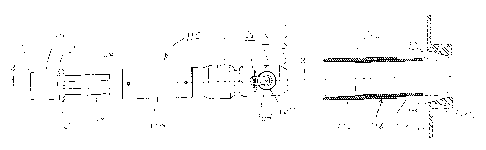
Figures A - L are schematic axial sectional views along a drill string
illustrating use of
the valve device of the present invention.
Figure 1 is an axial sectional view of an upper end of a casing string
positioned in a
drill floor with slips in place and a valve device, shown in side elevation,
aligned for
insertion into the string.
Figure 2 is an axial sectional view through the valve device as shown in
Figure 1.
Figure 3 is a transverse sectional view through the collet section taken along
line 3-3 on
the Fig 2.
Figure 4 is a transverse sectional view through the flapper valve section
taken along
line 4-4 on Fig 2.
Figure 5 is an axial sectional view of the valve device of Figure 1 shown
inserted into
the top end of a casing drill string which is secured by slips to the drill
floor.
Figure 6 is an axial sectional view of the casing joint with the casing
coupling on the
top end and side elevation of a top drive extension with a stinger tip which
is fastened to
the bottom end of the top drive member.
Figure 7 is an axial sectional view through the stinger tip and the valve
device of Figure
1 inserted into the top end of the casing string which is secured by slips to
the drilling
floor and showing a valve retaining clamp installed on the upper end of the
drill string.
DMSLegal\032361\00173\ 1429434v1
CA 02417746 2003-O1-30
Figure 8 is a side elevation of locked Casing Coupling Clamp.
Figure 9 is a transverse view along lines 9-9 on Fig. 8 showing clamped and
locked
valve retaining clamp.
Figure 10 is an axial sectional view through the valve retaining clamp taken
along lines
10-10 on Fig 9
Figure 11 is a transverse view taken along lines 9-9 on Fig 8 showing an open
valve
retaining clamp.
Figure 12 is an axial sectional view of the gas valve assembly including a
valve device
inserted into the top end of the casing string that is secured into the drill
floor by slips.
Fingers at the top end of the valve device are hooked above the torque ring.
Stinger tip is
fully engaged and valve retaining clamp is attached to the top casing
coupling.
Figure 13 is an axial sectional view of the completed joint when slips are
removed and
the drilling operation continues.
Figure 14 is a axial sectional view of another valve device according to the
present
invention.
Detailed Description of the Present Invention
Referring to Figures A, a valve device 10 according to the present invention
is shown
inserted into a drill string 12 inner diameter ID12. Valve device 10 is
positioned adjacent
an upper end of the drill string and acts to seal fluid flow out from the
drill string inner
diameter. In particular, drill string is being used for casing drilling with
compressed air
as the drilling fluid and, as such, the pressure within drill string Pds is
much greater than
the atmospheric air pressure Pa. IF valve device 10 was not present in drill
string 12, air
pressure Pds would be lost each time the top drive is removed, for example, to
engage
another drill string tubular for connection into the drill string, as shown in
Figure A.
In the illustrated embodiment, drill string 12 is formed of casing and
includes a plurality
of casing joints 14a, 14b connected by couplings 16a, 16b.
o,~nsm6~no~r;cnum7:~~ ia~<>asam 7
CA 02417746 2003-O1-30
Valve device 10 includes a valve body 26 having a bore 28 extending from its
upper end
to its lower end and a one-way valve 30 therein which prevents fluid flow
through the
bore except from the upper end to the lower end. Valve device 10 further
includes a seal
31 disposed thereabout to prevent fluid passage about the annulus between
valve body 26
and the drill string inner diameter.
Because pressure Pds is much greater than Pa, a valve retaining clamp 32 is
secured over
the open upper end of the drill string to prevent valve device 10 from be
expelled from
the drill string by the pressure differential. Valve retaining clamp 32
includes a return 34
at its lower end for engaging under connection 16b and a return 36 at its
upper end for
extending out over the open end of coupling 16b. Return 36 defines a bore 38
therethrough which is selected to prevent passage therethrough of valve device
10.
Figures A to L illustrate schematically use of a valve assembly according to
the present
invention and therefore a method according to the present invention.
Valve device 10 is positioned in drill string 12 and can be used, for example,
with a top
drive indicated generally at 40. The top drive is useful for manipulating the
drill string
by supporting and rotating the drill string to drill a borehole and by
connecting further
casing joints 14c to those already connected into the drill string to increase
the length of
the drill string. In particular, a casing joint 14c is engaged by the top
drive threading into
a coupling 16c installed on it. The casing joint 14c is then brought, as by
hoisting the top
drive, over the drill string 12, which is held in the drill floor 42, for
example by slips 44,
and casing joint 14c is aligned with a threaded into coupling 16b on the upper
end of the
drill string.
In the present method, wherein valve device 10 is positioned in the drill
string, the valve
device must be moved up through casing joint 14c to remain adjacent the upper
end of
the drill string to prevent the drill string from loosing pressure Pds. As
such, valve device
is releasably engageable to top drive 40, and in particular, to an extension
conduit 46
extending down from the top drive. Extension conduit 46 extends out from top
drive 40 a
length L46 greater than the combined length of casing joint 14c and it's
connected
coupling 16c. As such, when a casing joint and coupling are connected to the
top drive,
DMSl.egal\0323G1\00173\ 1429434v1
CA 02417746 2003-O1-30
the extension conduit extends through the casing joint and coupling and a
bottom end
portion 48 of the extension extends out beyond the lower end of the casing
joint. This
bottom end portion 48 extends through bore 38 in the valve retaining clamp and
engages
the valve device when the top drive brings casing joint 14c over into
engagement with the
drill string, Figures A and B. Note that borc 38 in the upper return must be
sized to
permit passage therethrough of the extension bottom end portion.
When the extension engages the valve device, valve retaining clamp 32 can be
removed,
Figure C, since it is no longer needed to retain the valve device in the drill
string, that
action being accomplished by the extension. Removal of the valve retaining
clamp 32
also opens coupling 16b for threaded insertion of casing joint 14c, Figure D.
In so doing,
the weight of the drill string, now including casing joint 14c, is supported
on top drive 40
such that slips 44 can be removed, Figure E, and the drill string can be
driven down
resuming drilling, Figure F. During drilling, drilling fluid is injected,
arrows D, through
top drive 40, extension conduit 46, bore 28 and valve 30 into the drill string
inner
diameter. In addition, valve device 10 is, during drilling, engaged on the
bottom end
portion 48 of the extension conduit.
When coupling 16c is lowered substantially beneath drill floor 42, drilling is
stopped and
the top drive is removed, Figure G, to engage a further casing joint. Prior to
removal of
the top drive, the drill string must again be supported by slips 44 in drill
floor 42. As top
drive 40 is removed, extension conduit 46 is withdrawn from casing joint 14c
and, since
valve device 10 is connected thereto, it is drawn with the extension up into
and through
casing joint 14c toward coupling 16c. With reference to Figure H, in
preparation for
removal of top drive 40 and its connected extension 46 from the drill string,
valve
retaining clamp 32 is again secured over the open upper end of the drill
string, which is
now coupling 16c.
When valve device 10 reaches the open upper end of the drill string, it is
released from
engagement with the extension conduit and remains in the drill string, Figure
I. Release
can be achieved by various means, such as by abutment against clamp 32, which
forces
DMSC,egal\032361\00173\ 1429434v1
CA 02417746 2003-O1-30
the engagement to be released or by release of engagement means acting between
the
valve device and the extension conduit, or a combination thereof.
In any event, with reference to Figure J, the valve device remains in the
drill string to
maintain pressure Pds by action of one way valve 30 and seal 31 and the top
drive is free
to move to pick up another casing joint. The drilling process and manipulation
of the
drill string will continue as shown in Figures A to J.
Refernng to Figures K and L, it is noted that in casing drilling the next
casing joint 14d is
retained in what is commonly referred to as a mouse hole 50. It will be
apparent that the
mouse hole may have to be modified to permit passage therein of the extension
conduit,
as for example by forming an opening through chc bottom end 52 thereof.
Referring to Figures 1 to 5, another valve device 110 is shown according to
the present
invention. Valve device 110 is shown aligned for insertion into an upper open
end of a
drill string 112, including a casing joint 114 and threaded thereto a coupling
116,
supported in a drill floor 142 by slips 144.
Valve device 110 includes a valve body 126 having a bore 128 extending from
its upper
end 126a to its lower end 126b and a one-way flapper valve 130 therein which
prevents
fluid flow through the bore except from the upper end to the lower end. In the
illustrated
embodiment, the valve body is formed in sections which are threaded, secured
or
fastened together to facilitate manufacture. Valve device 110 further includes
a seal 131
disposed thereabout to prevent fluid passage upwardly about the annulus
between valve
body 126 and the drill string inner diameter, when the valve device is
installed in the drill
string with end 126b directed downwardly.
Flapper valve 130 is pivotally connected to the body and biased by a spring
160 to seal
against seat 162 to prevent flow upwardly from lower end 126b to upper end
126a but
can be opened by flow downwardly through the bore, as by injection of drilling
fluid. In
the illustrated embodiment, an extension 164 is provided on the opening side
of seat 162
wherein flapper valve can open into the extension. Extension 164 spaces the
turbulence
from the flapper valve to extend its useful life by reducing vibration effects
on the
DMSLegal\0323G1100173\ 1429434v1 l~
CA 02417746 2003-O1-30
flapper, the turbulence being created by the fluid flow stepping from the
valve diameter
to the drill string inner diameter. To permit the flapper valve to be out of
the way of the
high velocity drilling fluid, as it is pumped through the bore, extension 164
includes a
recess 165 (configured as an opening in the illustrated embodiment) into which
flapper
valve 130 can extend when in the open position.
Valve device 110 includes an engaging means which holds the device in the
upper end of
the drill string except when it is in engagement with and driven by the top
drive. In
particular, in the illustrated embodiment the engaging means includes a
plurality of collet
fingers 166 integral with or attached to (as shown) the valve body. Collet
fingers 166 are
biased outwardly and include radially outwardly extending lugs 168 configured
to engage
against a stepped portion 170, such as the pin end face or the torque ring end
face, on the
drill string inner wall. The flex in collet fingers 166 and the configuration
of the radially
outwardly extending lugs 168 are selected to hold the valve device on the
stepped portion
preventing it from dropping down the drill string by gravity. However, this
engagement
can be overcome by force of the top drive, as will be described hereinbelow.
Collet
fingers 166 are formed to also have inwardly extending lugs 182, as will be
appreciated
herein below, for engagement to the top drive. A tube 171 extends about and
beyond
fingers 166 so that they are protected, to some extent, and to ease passage of
internal
members past the fingers without catching on them.
With reference also to Figures 6 and 7, in the illustrated embodiment, the
valve device
110 is moved by through the drill string by an extension 146 of the top drive
140.
Extension 146 extends downwardly from the top drive threads 147 and is
configured to
fit within and extend out from a casing joint 114/coupling 116 which is
engaged to the
top drive. Extension 146 includes a conduit through bore 170 through which
drilling
fluid can be pumped and a bottom end portion 148 sized and configured to fit
within a
landing portion 172 formed in valve body 126. Landing portion 172 is, in the
illustrated
embodiment, an enlarged portion of bore 128 and includes a bottom bearing 174,
such as
a bronze ring, against which portion 148 can bear.. A radial bearing ring 176
is also
provided to ease interface between the valve body and the extension. Seals 178
are
housed in glands 180 to provide a seal between the valve body and the
extension against
DMSL.egal\032361\00173\ 1429434v1 11
CA 02417746 2003-O1-30
fluid flow therethrough such that any fluid injected through bore 170 can be
passed
through valve substantially without leaking.
Extension 146 includes an outer diameter sized to fit snugly between collet
fingers 166
with an outer diameter slightly less than the diameter of the space between
lugs 182 on
the collet fingers so that the collet fingers are not free to bias inwardly
while the
extension passes therebehind. However, extension 146 includes an annular
groove 181
spaced from its lower end a space corresponding generally to the distance
between lugs
182 and bottom bearing 174 so that the groove is positioned behind the lugs
182 when the
extension is positioned against bearing 174 and is, therefore, fully inserted
into landing
portion 172. In this position, fingers 166 are free to be forced radially
inwardly toward
extension 14(i.
Refen-ing also to Figures 8 to 11, it was noted hereinbefore that a valve
retaining clamp
132 is useful for retaining valve device 110 in the drill string when the top
drive
extension is not bearing thereagainst. Valve retaining clamp 132 includes a
lower return
134, which engages under coupling 116, and an upper return 136, which extends
over the
open upper end of the drill string and is sized to be abutted by valve body
126 to prevent
it from passing therethrough. Return 136 defines an aperture 138 through which
extension 146 can be inserted to engage valve device 110. As shown, the edges
of return
136 about the aperture can be ramped, at 147, to facilitate insertion of the
extension
therethrough. In one embodiment, the diameter of aperture 138 can be selected
to
correspond with or be greater than bore 128 inner diameter at tube 171 so that
the
extension is substantially prevented from bumping the valve device, and
thereby
disengaging it from stepped portion 170, during insertion.
Clamp 132, for ease of use, can be configured as shown. In particular, clamp
132 can
include a first semicircular half 184a, 184b pivotally connected at hinge 186
and
releasably lockable at latch 188. Latch 188 can be spring biased to permit
automatic
locking when the halves are pivoted together. A lock pin 190 can be secured
between
alignable holes 191 on either side of the latch as a safety measure to prevent
inadvertent
unlatching. Handles 192 can be provided to facilitate handling.
DMSLegnl\032361\00173\ 1429434v1 I2
CA 02417746 2003-O1-30
In use and with reference to Figures 12 and 13, the valve assembly can be used
to retain
the pressure in a drill string, wherein compressed gas is used as a drilling
fluid. In such
an embodiment, the valve device 110 is positioned in a drill string 112
adjacent the upper
end thereof with lugs 168 of collet fingers 166 engaged against the stepped
portion 170 as
formed by torque ring or pin end face. Wherein there exists or is generated a
pressure
differential between the drill string inner diameter and atmosphere, clamp 132
is secured
over the open end of the drill string to prevent the valve device from being
expelled
therefrom.
The top drive 140 is used to engage casing joints, such as casing joint 114x,
and bring
them for connection into the drill string in which the valve device is
engaged. As a
casing joint is brought into alignment with the upper end of the drill string,
extension 146
will pass into landing portion of the valve body and eventually engage against
the bottom
bearing 174, at this point groove 181 will be positioned in line with lugs
182. Force can
then be applied against the valve body by the extension to drive lugs 168 out
of
engagement with stepped portion 170 wherein the fingers 166 are forced
inwardly. In
this configuration, however, lugs 182 engage against stepped edges of groove
181 and the
fingers are prevented from biasing out of engagement with the extension, as
limited by
abutment of lugs 168 against the inner wall of the drill string. This provides
engagement
between extension 146 and valve device 110 so that it is moved down as the top
drive
brings in casing joint 114a to be connected to coupling. At this point, clamp
132 must be
removed to provide access to the threads of coupling 116.
Drilling can now resume with drilling fluid being pumped through conduit 173,
bore 128
and past flapper valve 130. When the whole connection descends below the drill
floor a
new connection has to be made again. Top drive; 140 will unscrew from the top
casing
coupling 116a and the whole assembly of extension 146 and valve device 110
engaged
thereto will be pulled up through casing joint 114a.
In order to assure that valve device 110 remains in the top part of the casing
string a
clamp 132 is fastened on the top casing coupling. When pulling up the
extension with
the valve device hooked thereon, upper end 126a of the device will abut
against the return
DMSL,egal\032361\00173\ 1429434v1 13
CA 02417746 2003-O1-30
134. At this point, when valve fingers 166 will be positioned above stepped
portion 170
and free to open radially outwards and disengage from groove 181 on the OD of
the
extension. At the same time, lugs 168 of the fingers will now engage the
stepped portion,
as provided by the torque ring or the ID of the casing. As will be appreciated
the distance
between end 126a and lugs 168 should be less than the distance between the
upper end of
the drill string (or in any event the return 136 on clamp) and stepped portion
170 for
engagement between lugs 168 and stepped portion 170 to be permitted. Valve
device
110 will now be secured in this uppermost top position while extension is
disengaged
completely. Flapper valve 130 is closed and compressed gas in the casing
string is
prevented from escaping due to the valve closure and seal 131. A new casing
joint
connection can be made on the top drive and extension inserted into the valve
device.
The whole process can be repeated without escape of the compressed gas.
With reference to Figure 14, another valve device 210 is shown which is
intended for use
in larger diameter drill strings that that device 110 of Figures 1 to 13. In
particular, while
device 210 is generally similar to device 110, flapper valve 230 can be
positioned in a
section of body 226 which permits the valve more room but does not affect
operation
thereof. Seal 131 is moved down since there is no opening 165 about the
flapper.
DMSLegal\032361\00173\ 1429434v1 14