Language selection

Search

Patent 2418219 Summary

Third-party information liability

Some of the information on this Web page has been provided by external sources. The Government of Canada is not responsible for the accuracy, reliability or currency of the information supplied by external sources. Users wishing to rely upon this information should consult directly with the source of the information. Content provided by external sources is not subject to official languages, privacy and accessibility requirements.

Claims and Abstract availability

Any discrepancies in the text and image of the Claims and Abstract are due to differing posting times. Text of the Claims and Abstract are posted:

  • At the time the application is open to public inspection;
  • At the time of issue of the patent (grant).
(12) Patent Application: (11) CA 2418219
(54) English Title: PAPER MACHINE CLOTHING, ESPECIALLY PRESS FELT
(54) French Title: HABILLAGE DE MACHINE A PAPIER, EN PARTICULIER FEUTRE DE PRESSE
Status: Deemed Abandoned and Beyond the Period of Reinstatement - Pending Response to Notice of Disregarded Communication
Bibliographic Data
(51) International Patent Classification (IPC):
  • D21F 7/08 (2006.01)
  • D02G 3/44 (2006.01)
  • D03D 1/00 (2006.01)
  • D04H 3/10 (2012.01)
(72) Inventors :
  • TELGMANN, DIETER (Germany)
(73) Owners :
  • HEIMBACH GMBH & CO.
(71) Applicants :
  • HEIMBACH GMBH & CO. (Germany)
(74) Agent: SMART & BIGGAR LP
(74) Associate agent:
(45) Issued:
(22) Filed Date: 2003-01-31
(41) Open to Public Inspection: 2003-08-01
Examination requested: 2003-03-20
Availability of licence: N/A
Dedicated to the Public: N/A
(25) Language of filing: English

Patent Cooperation Treaty (PCT): No

(30) Application Priority Data:
Application No. Country/Territory Date
102 04 357.4-27 (Germany) 2002-02-01

Abstracts

English Abstract


A paper machine clothing, especially a press felt (1),
includes a support (2) which has at least one layer of a
thread lap (3, 4, 5, 13) and. which is embedded in a fiber
matrix. Lap threads (6, 7, 8, 9, 10, 14, 17, 21, 25, 26,
27, 28, 33, 38, 43, 44, 45) run parallel to one another.
The lap threads (10, 14, 17) are provided with outwardly
projecting fibers (12, 16, 19).


Claims

Note: Claims are shown in the official language in which they were submitted.

We Claim:
18

1. Paper machine clothing, especially a press felt (1),
with a support (2) which has at least one layer of a
thread lap (3, 4, 5, 13) with lap threads (6, 7, 8,
9, 10, 14, 17, 21, 25, 26, 27, 28, 33, 38, 43, 44,
45) running parallel to one another, characterized
in that lap threads (10, 14, 17) are provided with
outwardly projecting fibers (12, 16, 19).
2. Paper machine clothing according to claim 1, charac-
terized in that the fibers (12, 16, 19) predomi-
nantly project at an angle toward the surface of the
lap threads (10, 14, 17) which deviates from 0 to
60 from vertical to the surface.
3. Paper machine clothing according to claim 1 or 2,
characterized in that the fibers (12) are glued to
the lap threads (10).
4. Paper machine clothing according to claim 3, charac-
terized in that the fibers (12) are electrostati-
cally applied.
5. Paper machine clothing according to one of claims 1
to 4, characterized in that lap threads (14) are
constructed as chenille threads with outward pro-
jecting fibers.
6. Paper machine clothing according to one of claims 1
to 5, characterized in that the fibers (12, 16, 19)
19

have a length of at least 0.5 mm, preferably 1 to
1.6 mm.
7. Paper machine clothing according to claims 1 to 6,
characterized in that the lap threads (10) are con-
structed as monofils with outwardly projecting fi-
hers.
8. Paper machine clothing according to claim 7, charac-
terized in that the monofils have a diameter from
0.3 to 0.6 mm.
9. Paper machine clothing according to claim 7 or 8,
characterized in the monofils are roughened such
that outwardly projecting fibers are formed from
their material.
10. Paper machine clothing according to one of claims 1
to 9, characterized in that the lap threads (14) are
constructed as twines of individual threads with
outward projecting fibers.
11. Paper machine clothing according to one of claim 10,
characterized in that the twines consist of two to
twelve monofil individual fibers with a diameter
from 0.1 to 0.3 mm in each case.
12. Paper machine clothing according to one of claim 10
or 11, characterized in that the twines are con-
structed as multifilaments.

13. Paper machine clothing according to claim 10 or 11,
characterized in that outwardly projecting fibers
(16) are clamped between the individual threads.
14. Paper machine clothing according to claims 1 to 13,
characterized in that spacing threads are present
which run between two lap threads (6, 7, 8, 10, 14,
17, 21, 25, 26, 27, 28, 33, 38, 43, 44, 45) and are
soluble in a solvent in which the remaining part of
the paper machine clothing (1) is not soluble.
15. Paper machine clothing according to one of claim 14,
characterized in that the spacing threads run paral-
lel to the lap threads (6, 7, 8, 9, 10, 14, 17, 21,
25, 26, 27, 28, 33, 38, 43, 44, 45).
16. Paper machine clothing according to claim 14 or 15,
characterized in that the spacing threads are in any
given case so wrapped about a lap thread or are en-
twined with this such that it projects outwardly.
17. Paper machine clothing according to claims 14 to 16,
characterized in that the spacing threads are water-
soluble.
18. Paper machine clothing according to one of claims 14
to 17, characterized in that lap threads are wound
or entwined with spun fiber yarn.
19. Paper machine clothing according to one of claims 1
21

to 18, characterized in that lap threads (21, 25,
26, 27, 28, 33, 38, 43, 44, 45) are constructed as
screw-like contoured monofils.
20. Paper machine clothing according to claim 19, char-
acterized in that screw-like contoured monofils (21,
25, 26, 27, 28, 33, 38, 43, 44, 45) are present
which have an oval, trilobate, polygonal, square,
rectangular, cloverleaf and/or triangular cross sec-
tion.
21. Paper machine clothing according to claim 19 or 20,
characterized in that screw-like contoured monofils
(21, 33) are present, the cross section of which has
downward warpings (24, 34, 35) distributed over its
periphery.
22. Paper machine clothing according to one of claims 19
to 21, characterized in that screw-like contoured
lap threads (38) are present the cross section of
which has several upward warpings (39, 40, 41, 42)
distributed over its periphery.
23. Paper machine clothing according to claim 21 and 22,
characterized in that screw-like contoured lap
threads are present the cross section of which has
downward and upward warpings alternatingly distrib-
uted over its periphery.
22

24. Paper machine clothing according to claim 23, char-
acterized in that screw-like contoured lap threads
are present which are provided with outwardly pro-
jecting fibers.
25. Paper machine clothing according to one of claims 19
to 24, characterized in that screw-like contoured
lap threads (21) are present the contour of which
has screw-like running sharp corners.
26. Paper machine clothing according to one of claims 19
to 25, characterized in that the contour of the
screw-like contoured lap threads (21) the contour of
which has screw-like running rounded off edges.
27. Paper machine clothing according to one of claims 19
to 26, characterized in that the contour of the
screw-like contoured lap threads (21, 25, 26, 27,
28, 33, 38, 43, 44, 45) have two to forty threads
over 10 cm of length.
28. Paper machine clothing according to one of claims 1
to 27, characterized in that at least 30% of the lap
threads extending longitudinally and/or transversely
are screw-like contoured monofils (21, 25, 26, 27,
28, 33, 38, 43, 44, 45).
29. Paper machine clothing according to one of claims 19
to 28, characterized in that twines are present in
23

which several screw-like contoured monofils are en-
twined with one another or at least one screw-like
contoured monofil is entwined with other monofils
and/or multifilaments.
30. Paper machine clothing according to one of claims 1
to 29, characterized in that the support is con-
structed in one layer or several layers.
31. Paper machine clothing according to one of claims 1
to 30, characterized in that the support consists of
several support tracks (2, 4, 5) not connected among
one another by threads.
32. Paper machine clothing according to one of claims 1
to 31, characterized in that the support has a woven
fabric, a knitted fabric and/or a network and addi-
tionally a thread lap.
33. Paper machine clothing according to one of claims 1
to 32, characterized in that the support (2) is en-
closed between at least two fiber layers.
34. Paper machine clothing according to one of claims 1
to 32, characterized in that the lap threads (6, 7,
8, 10, 14, 17, 21, 25, 26, 27, 28, 33, 38, 43, 44,
45) and if need be the spun fiber yarns are made of
a thermoplastic polymer such as polypropylene, poly-

amide 4,6, polyamide 6, polyamide 6.6, polyamide
6.10, polyamide 6.12, polyamide 11, polyamide 12,
PET, PTT, PBT, PPS, PEK, PEEK or an elastomer poly-
ester.

Description

Note: Descriptions are shown in the official language in which they were submitted.


CA 02418219 2003-O1-31
Paper Machine Clothina, especiallv Press Felt
The invention concerns a paper machine clothing,
especially a press felt, with a support which has at
least one layer of a thread lap with lap threads running
parallel to one another, and which is embedded in a fiber
matrix.
Paper machine clothes are bands of great length and
width circulating in paper machines which serve to form
and guide the paper web through the paper machine. Their
construction depends greatly upon in which part they are
installed in the paper machine. Press felts in which a
support is embedded in a fiber matrix are usually for the
pressing part in which the previously formed paper web is
mechanically dehydrated. The support in particular
serves to accommodate the tractive forces acting upon the
press felt and is primarily constructed as a fabric
whereby the support can be constructed of several support
tracks not connected with one another. A fiber fleece is
then unilaterally or bilaterally sewn onto this support
which provides protection of the support from wear and
tear and provides far even surfaces.
Instead of a fabric, thread laps in single and
multiple layer construction can also be provided. Such
representative press felts can, for example, be gathered

CA 02418219 2003-O1-31
from EP-B-0 394 293 and EP-A-0 038 276. The thread laps
are distinguished in that they consist of a large number
of lap threads running parallel to one another, whereby
the lap threads can extend longitudinally as well as
transversely. These distances should be as equal as
possible and remain constant over the extension of the
lap threads so that the dehydration properties of the
press felt are even over its surface. Nonetheless, it
creates problems in manufacturing such press felts to
ensure such equal and constant distances especially
during the needle stitching process for the purpose of
connecting and fastening the fiber fleece layers (cf. DE-
C-40 40 861) .
Wrapping lap threads with spun fiber yarns is
proposed with the press felt according to EP-0 394 293.
Nonetheless, one is restricted with these lap threads to
twined threads. Their manufacture is expensive and
therewith cost intensive owing to the twining process.
The twines cannot be relied upon for manufacture of a
wire seam, so that providing a press felt of this type
with a seam presents difficulties. Moreover, they lead
to a premature thickening of: the Zap owing to which the
dehydration properties worsen.
2

CA 02418219 2003-O1-31
The invention is based on the objective of
developing a paper machine clothing with a thread lap
such that the lap threads used with the known press felt
with wrapped spun fiber yarns are replaced by more simply
and economically manufactured lap threads with basically
identical processes, and in this way the possibility of
using monofils for these lap threads is also opened.
This object is accomplished in accordance with the
invention in that lap threads are provided with outwardly
projecting fibers, whereby the fibers should preferably
chiefly project vertically in relation to the surface of"
t he 1 ap t breads or at an angl a of up t o 60 i n rel at i on
to the vertical. Such lap threads replace the lap
threads wrapped with spun fiber yarns as they are known
from EP-B-0 394 293 at least partially, but preferably
completely, whereby not all lap threads need be
constructed in this manner, but it is more appropriate.
The advantage of such lap threads lies in the fact that
they can basically be manufactured more simply and
therewith more economical:Ly, for example by gluing the
threads and here in particular by electrostatic
depositing or construction as chenille fibers. This
opens up the possibility which previously did not exist
with threads wrapped with spun fiber yarn of using
3

CA 02418219 2003-O1-31
monofils of the most varied diameters, preferably in the
range between 0.3 and 0.6 mm and giving them the same
property which was brought about by wrapping the lap
threads with spinning fiber year. Moreover, the
projecting threads can be created not only by
electrostatic depositing, but also by roughening,
especially scraping the material of the monofils.
The use of monofils permits manufacturing the stitch
felts on the lap basis because the monofils are suited
for forming loops on the end corners of the paper machine
clothing and through which these ends can be connected
using a wire inserted through the loops. Such seam felts
are especially basically easier to insert into the
pressing part of a paper machine than press felts
manufactured in an endless manner.
Of course, there also exists the possibility of
constructing the lap threads with outwardly projecting
fibers as twines of individual threads, preferably
individual threads of two to twelve monofils with a
diameter from 0.1 to 0.4 mm in each case, or as
multifilaments. Even these threads can be
electrostatically applied. instead of this, there exists
the possibility of clamping the outwardly projecting
fibers between the individual fibers.
4

CA 02418219 2003-O1-31
It is provided i.n accor_dance with a further feature
the invention in that spacing threads are present which
run between two lap threads and are soluble in a solvent
in which the remaining part of- the paper machine clothing
is not soluble. The basic concept of the invention is
thus to provide spacing threads between the lap threads
(and indeed preferably between all lap threads) which
keep the lap threads at a predetermined distance which
remains constant over their extension. In this way they
stabilize the position of the lap fibers and ensure their
even distribution over the surface. Since they are
introduced with the manufacture of the support,
displacements of the lap fibers do not occur during
subsequent manufacturing steps, especially during
embedding the support into a fiber matrix, for example by
needle stitching of fiber fleeces. That is, their
distribution is maintained until finishing the paper
machine clothing. Only then are the spacing fibers
dissolved out in order to obtain the desired water
permeability.
The dissolution out can take place before insertion
into the paper machine r_hrough a corresponding washing
step or, however, first after insertion whereby the
dissolution takes place through the liquid pressed out of

CA 02418219 2003-O1-31
the paper web during an intake phase. In both cases, it
is appropriate for the spacing fibers to be water
soluble, whereby in particular threads of polyvinyl
alcohol offer themselves. In the end, in this way a paper
machine clothing is obtained with a support having at
least one fiber lap which is distinguished by very even
dehydration properties over the surface.
To be sure, incorporating soluble fibers or threads
into paper machine clothes and dissolving them out before
insertion into the paper machine or in an intake phase
has been known in the state of the art for a long time .
This nonetheless took place in order to make the paper
machine clothing water-permeable in general or to enlarge
its internal hollow spaces to such an extent that this
could not be reached through normal manufacturing
processes, and in this way to enlarge the dehydration
output (cf. US-A-4,482,601, EP-B-0 466 990, EP-A-0 567
206, EP-B-0 413 869; WO 98/07925; EP-A-0 123 431; DE-A-24
37 303; DE-U-70 31 398). Moreover, such fibers were also
used which are not soluble when inserted into the paper
machine and which were first removable through a separate
washing scouring solution. The reason for this measure
was to restore the original water permeability reduced by
contamination again. In both cases, the goal is not
6

CA 02418219 2003-O1-31
comparable with that which is the basis of the present
invention.
In a first development of the basic conception of
the invention, the spacing threads run parallel to the
lap threads. That is the lap threads and the spacing
threads lie side by side, whereby it is apparent that
have a constant cross sect=ion over their extension.
Moreover, as a rule, one spacing thread between two lap
threads suffices so that one lap fiber always alternates
with one spacing thread. As an alternative, it can be
provided that the spacing threads are in each case
wrapped around a lap fiber or entwined with this such
that they project externally. In this way, the threads
come to lie point by point upon one another, and indeed
the spacing threads when all. lap threads are wrapped or
are entwined with spacing fibers, or by one spacing
thread and one lap thread in any given case when only
every second lap thread is wrapped by a spacing thread or
is entwined with it. This point by point contact can be
transformed into a line contact if the lap threads are
wrapped completely by thc~ spacing fibers and are
constructed, for example, as surface threads or bands.
According to a further feature of the invention, it
is provided that the lap threads are enveloped or
7

CA 02418219 2003-O1-31
entwined with a spun fiber yarn such as provided, for
example, in the paper machine clothing according to EP-B-
0 394 293.
In order to improve the dehydration properties even
further, it is provided in accordance with the invention
that a part or all lap threads are constructed as
contoured monofils. They thus have an off round cross
section in which the profile runs screw-like or spiral-
like viewed in the longitudinal direction of the monofil.
The respective monofil is thus rotated about its long
axis with respect to its outer configuration. A part of
these or all these monofils can also be provided with
outwardly projecting fibers, especially be
electrostatically provided with these.
By using the screw-like contoured lap threads of the
invention, the open volume inside the paper machine
clothing is increased and better_ dehydration properties
result. The effect can be varied by the number,
construction and arrangement of these lap threads to a
considerable extent and therewith adapted to the
standards in question. Moreover, it does not depend upon
whether the lap threads stand under torsion tension
inside the paper machine clothing. They are thus twisted
only after their manufacture and have been inserted into
8

CA 02418219 2003-O1-31
the paper machine clothing in this condition, or if the
screw-like contouring was already impressed during
manufacture, for example during extrusion through
appropriate nozzle shapes or during subsequent
stretching. For this reason, the monofils lie without
tension in the paper machine clothing. Such screw-like
contoured monofils are suited for replacing twines which
must be separately manuf<~ctured from monofils or
multifils.
Using flat threads rectangular in cross section or
other cross section shape; of threads as well for the
supports of paper machine clothes which are in part
strongly contoured for specified purposes is indeed
known. (Cf. DE-A-40 31 608; US-A-5,361,808; DE-A-195 45
386; US-A-5,591,525; EP-A-1 067 239, DE-A-199 00 989.)
The contouring of these threads moreover takes place for
the most varied of reasons. Nonetheless, common to all
threads is that the contour is longitudinally stretched,
thus extended in the axis of the respective thread and is
consequently not twisted.
Great freedom exists with respect to the
construction of the cross sections of the screw-like
contoured monofils. They thus can have an oval,
trilobate, polygonal, square, rectangular, clover-leaf
9

CA 02418219 2003-O1-31
and/or triangular cross section, whereby the cross
sections need not even be' regular or symmetrical.
Moreover, monofils of diffe:re:nt cross section can also be
present in order correspondingly t.o exert an influence on
the pore volumes and therewith assume the dehydration
properties in accordance with the standards. An
especially high pore volume results when screw-like
contoured monofils are present, the cross section of
which has several down warpings over its periphery. In
contrast, however, up warpings distributed over the
periphery can also be provided, or both can be combined
with each other such that down and up warpings are
alternatingly distributed over the periphery. Moreover,
sharp or rounded off corners running screw-like can also
be provided.
It has proven to be beneficial if the contour of the
screw-like contoured monofils has two to forty threads
over 10 cm, thus that the cross section of the monofils
is twisted two to forty times in this length. But the
volume of the pores arid therewith the dehydration
properties can also be influenced through the number of
threads. Here monofils with a different number of
threads can also be provided.

CA 02418219 2003-O1-31
Influence on the pore volume and therewith the
dehydration capacity can also be exerted through the
number of screw-like contoured monofils. Appropriately
at least 30% of the lap thre;~ds extending longitudinally
and/or transversely should be screw-like contoured
monofils, whereby also all longitudinally and/or
transverse threads can be such monofils.
Basically, there also exists the possibility of
processing the screw-like profiled monofils into twines,
for example such that several screw-like contoured
monofils are entwined with one another. But there also
exists the possibility of entwining one or more screw-
like monofils with monofils shaped in another manner, for
example stretched contoured monofils or round monofils
and/or multifilaments.
There exist no restrictions with respect to the
layer characteristic of tree support. That is, the
support can be constructed with one layer or many layers
or can also consist of several support tracks not
connected with one another through threads, which are
identically constructed or are also different. Moreover,
the support can also have a woven fabric, knitted fabric
and/or a network as long as a layer of thread lap is
present.

CA 02418219 2003-O1-31
It is advantageous for use in a press felt if the
support is embedded into a fiber matrix in which it is
enclosed between at least two fiber layers which are
needle stitched with each other. As regards the material
of the lap threads, materials typical for paper machine
clothes can be used. These are in particular
thermoplastic polymers, for example polypropylene,
polyamide 4.6, polyamide 6, pol.yamide 6.6, polyamide
6.10, polyamide 6.12, polyamide 12, PET, PTT, PPS, PEK or
PEEK. Even elastomer polyesters are usable.
The invention is illustrated in greater on the basis
of embodiments in the drawing, wherein:
Figure 1 Is a cross section through a press felt with
thread laps as supports;
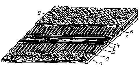
Figure 2 Illustrates a partial section of the press felt
in accordance with Figure 1 in three quarters
view, whereby in each case the upper layer
is shortened in relation to in each case the
lower layer;
Figure 3 Shows an electrostatically applied lap thread;
Figure 4 Depicts a cross section through a thread lap
with electrostatically applied lap threads;
Figure 5 Is a view of a lap thread constructed as twine
with clamped fibers;
1'?

CA 02418219 2003-O1-31
Figure 6 Illustrates a l.ap thread constructed as
chenille thread;
Figure 7 Shows a component of a lap thread constructed
as a screw-like contoured monofil;
Figure 8 Depicts a cross section through the lap thread
in accordance with Figure 7;
Figures 9
through 17 ReveaJ_ different cross sections of lap
threads which are constructed as screw-like
contoured monofi.ls.
The press felt 1 shown in Figures 1 and 2 has a
support 2 which consists of three layers laid one over
the other which are construr_ted in each case as thread
laps 3, 4, 5. All three thread laps 3, 4, 5 in each
consist of lap threads running parallel on the plane of
the press felt 1 (designated by way of example with 6, 7,
8) which in each case have the same distance from one
another. The lap threads 6, 8 of upper and lower thread
laps moreover run in the longitudinal direction of the
press felt 1 which at the same time is its direction of
travel, while the lap threads 7 of the central thread lap
4 extend transversely in relation thereto. The support 2
is embedded in the midd7.e of a fiber matrix 9 which is
13

CA 02418219 2003-O1-31
represented merely by layer in Figure 2 and arose by
needle stitching of fiber fleeces.
The press felt 1 can already be seen in its final
state. The distances between the lap threads 6, 7, 8 are
characteristic. These distances were brought about in
that spacing threads were worked in between the lap
threads 6, 7, 8 already during manufacture of the support
2, the extension of which in the plane of the respective
thread laps 3, 4, 5 corresponded to the now free distance
between lap threads 6, 7, 8 to be recognized in Figures 1
and 2. Moreover, the spacing threads can have a square
or rectangular cross section in order to avoid a sliding
one over the other of spacing threads and lap threads 6,
7, 8.
The support 2 is then covered with fiber fleeces and
run through a needle machine in which the fiber fleeces
are interlocked with and fastened to one another while
forming a fiber matrix 9. P4oreover the spacing threads
have ensured that displacements of the lap threads 6, 7,
8 has not occurred. Subsequently the spacing threads
have been dissolved under the action of a solvent (water
can be used as a solvent with spacing threads of
polyvinyl alcohol), on account of which the free spaces
between lap threads 6, 7, 8 resulted.
14

CA 02418219 2003-O1-31
Figure 3 depicts in side view a lap thread 10 which
has a monofil 11 which is electrostatically covered with
fibers basically projecting vertically from its surface,
designated by way of example with 12.
Figure 4 depicts a thread lap 13 with lap threads 10
in accordance with Figure 3, whereby the thread lap 13
consists of a large number of lap threads 10 arranged
alongside one another running parallel to one another,
which have the same distances from one another.
Figure 5 shows a lap thread 14 which consists of a
twine 15 with clamped fiber sheaves projecting vertically
between the individual threads of the twine 16,
designated with l6 by way of example. It is obvious that
these fiber sheaves 16 are distributed over the
periphery, to be seen simi:Lar to the case of the thread
lap 13.
Figure 6 depicts a lap thread 17 which is
constructed as a chenille thread with a core thread 18
and fibers basically projecting vertically from it,
designated by way of example with 19.
A lap thread 21 is represented in Figures 7 and 8
which is constructed as a monofil and is constructed with
a rotation symmetrical cross section with a core 22 and a
total of six radially outwardly projecting bars,

CA 02418219 2003-O1-31
designated by way of_ example with 23. The bars 23 are
enclosed between deep downward warpings-designated by way
of example with 24-which form grooves over the length
with the lap thread 21.
As is apparent from Figure 7, the contour of the lap
thread 21 is configured screw-like thus, inwardly twisted
on the basis of its outer configuration, so that the bars
23 and also the grooves formed by the downward warpings
24 run screw-like about the core 22 of the lap thread 21.
If such lap threads 21 are incorporated into the support
of a paper machine clothing, there arises a pore volume
owing to this whereby the grooves formed by the downward
warpings 24 form dehydration channels.
Other embodiments of lap threads 25, 26, 27, 28 are
represented in Figures 9 to 12. They are likewise
rotation-symmetrical and have a different number of
radially running bars, designated as 29, 30, 31, 32 by
way of example.
A lap thread 33 is disclosed in Figure 13 which is
only mirror-symmetrical. It has two opposed downward
warpings 34, 35 which run bilaterally into thickenings
36, 37 of different shape.
A screw-like configured lap thread 38 is represented
in Figure 14 which is constructed rotation-symmetrical
1.6

CA 02418219 2003-O1-31
and has four upward warpings 39, 40, 41, 42 distributed
over the periphery, whereby the upward warpings 39, 40,
41, 42 are connected through convex regions. Groove-like
depressions also result with this contour.
Further screw--like contoured lap threads 43, 44, 45
are represented in cross section in Figures 15 to 17, and
indeed with a regular pentagon (Figure 15), a square
(Figure 16) and a triangle (Figure 17). Even if the
connection of the corners or edges of these lap threads
43, 44, 45 form trenches, pore volumes and dehydration
channels arise through the screw-like contour.
17

Representative Drawing
A single figure which represents the drawing illustrating the invention.
Administrative Status

2024-08-01:As part of the Next Generation Patents (NGP) transition, the Canadian Patents Database (CPD) now contains a more detailed Event History, which replicates the Event Log of our new back-office solution.

Please note that "Inactive:" events refers to events no longer in use in our new back-office solution.

For a clearer understanding of the status of the application/patent presented on this page, the site Disclaimer , as well as the definitions for Patent , Event History , Maintenance Fee  and Payment History  should be consulted.

Event History

Description Date
Inactive: IPC deactivated 2020-02-15
Inactive: IPC assigned 2019-05-08
Inactive: IPC expired 2012-01-01
Application Not Reinstated by Deadline 2007-06-29
Inactive: Dead - No reply to s.30(2) Rules requisition 2007-06-29
Deemed Abandoned - Failure to Respond to Maintenance Fee Notice 2007-01-31
Inactive: Abandoned - No reply to s.30(2) Rules requisition 2006-06-29
Inactive: IPC from MCD 2006-03-12
Inactive: S.30(2) Rules - Examiner requisition 2005-12-29
Letter Sent 2004-05-11
Inactive: Transfer information requested 2004-05-10
Inactive: Single transfer 2004-04-05
Application Published (Open to Public Inspection) 2003-08-01
Inactive: Cover page published 2003-07-31
Letter Sent 2003-04-17
Inactive: First IPC assigned 2003-04-16
Request for Examination Received 2003-03-20
Request for Examination Requirements Determined Compliant 2003-03-20
All Requirements for Examination Determined Compliant 2003-03-20
Amendment Received - Voluntary Amendment 2003-03-20
Inactive: Courtesy letter - Evidence 2003-03-11
Inactive: Filing certificate - No RFE (English) 2003-03-05
Filing Requirements Determined Compliant 2003-03-05
Application Received - Regular National 2003-03-05

Abandonment History

Abandonment Date Reason Reinstatement Date
2007-01-31

Maintenance Fee

The last payment was received on 2005-11-23

Note : If the full payment has not been received on or before the date indicated, a further fee may be required which may be one of the following

  • the reinstatement fee;
  • the late payment fee; or
  • additional fee to reverse deemed expiry.

Patent fees are adjusted on the 1st of January every year. The amounts above are the current amounts if received by December 31 of the current year.
Please refer to the CIPO Patent Fees web page to see all current fee amounts.

Fee History

Fee Type Anniversary Year Due Date Paid Date
Application fee - standard 2003-01-31
Request for examination - standard 2003-03-20
Registration of a document 2004-04-05
MF (application, 2nd anniv.) - standard 02 2005-01-31 2004-11-25
MF (application, 3rd anniv.) - standard 03 2006-01-31 2005-11-23
Owners on Record

Note: Records showing the ownership history in alphabetical order.

Current Owners on Record
HEIMBACH GMBH & CO.
Past Owners on Record
DIETER TELGMANN
Past Owners that do not appear in the "Owners on Record" listing will appear in other documentation within the application.
Documents

To view selected files, please enter reCAPTCHA code :


To view images, click a link in the Document Description column. To download the documents, select one or more checkboxes in the first column and then click the "Download Selected in PDF format (Zip Archive)" or the "Download Selected as Single PDF" button.

List of published and non-published patent-specific documents on the CPD .

If you have any difficulty accessing content, you can call the Client Service Centre at 1-866-997-1936 or send them an e-mail at CIPO Client Service Centre.


Document
Description 
Date
(yyyy-mm-dd) 
Number of pages   Size of Image (KB) 
Description 2003-01-30 17 549
Claims 2003-01-30 8 181
Drawings 2003-01-30 4 95
Abstract 2003-01-30 1 10
Representative drawing 2003-04-16 1 39
Filing Certificate (English) 2003-03-04 1 169
Acknowledgement of Request for Examination 2003-04-16 1 174
Request for evidence or missing transfer 2004-02-02 1 103
Courtesy - Certificate of registration (related document(s)) 2004-05-10 1 106
Reminder of maintenance fee due 2004-10-03 1 110
Courtesy - Abandonment Letter (R30(2)) 2006-09-06 1 166
Courtesy - Abandonment Letter (Maintenance Fee) 2007-03-27 1 175
Correspondence 2003-03-04 1 24