Language selection

Search

Patent 2418356 Summary

Third-party information liability

Some of the information on this Web page has been provided by external sources. The Government of Canada is not responsible for the accuracy, reliability or currency of the information supplied by external sources. Users wishing to rely upon this information should consult directly with the source of the information. Content provided by external sources is not subject to official languages, privacy and accessibility requirements.

Claims and Abstract availability

Any discrepancies in the text and image of the Claims and Abstract are due to differing posting times. Text of the Claims and Abstract are posted:

  • At the time the application is open to public inspection;
  • At the time of issue of the patent (grant).
(12) Patent: (11) CA 2418356
(54) English Title: STATOR BLADE PIVOTING ARRANGEMENT IN A TURBOMACHINE
(54) French Title: AUBE PIVOTANTE DE STATOR DE TURBOMACHINE
Status: Term Expired - Post Grant Beyond Limit
Bibliographic Data
(51) International Patent Classification (IPC):
  • F01D 9/02 (2006.01)
  • F01D 17/16 (2006.01)
(72) Inventors :
  • CHATEL, ALAIN (France)
  • MAROIS, FABRICE (France)
  • RAULIN, DOMINIQUE (France)
(73) Owners :
  • SNECMA
(71) Applicants :
  • SNECMA (France)
(74) Agent: LAVERY, DE BILLY, LLP
(74) Associate agent:
(45) Issued: 2009-12-15
(22) Filed Date: 2003-02-04
(41) Open to Public Inspection: 2003-08-07
Examination requested: 2008-01-07
Availability of licence: N/A
Dedicated to the Public: N/A
(25) Language of filing: English

Patent Cooperation Treaty (PCT): No

(30) Application Priority Data:
Application No. Country/Territory Date
02 01459 (France) 2002-02-07

Abstracts

English Abstract

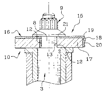
A spring (15) of angular shape is placed between the lug (17) of a connecting rod (10) controlling the orientation of a stator blade and the pivot (3) of said blade, such that its edge (18) bends against one edge face (19) of the connecting rod (10) and the washer (16) moves the pivot (3) in the play of the bore (21) of the connecting rod and sets and maintains the contact between two plane faces (12 and 13), so as to reduce the differences in angular displacements between the connecting rod and pivot due to the play remaining in the bore (21).


French Abstract

Un ressort (15) de forme angulaire est placé entre la patte (17) d'une bielle d'accouplement (10) qui commande l'orientation d'une aube de stator et du tourillon (3) de ladite lame, de telle sorte que son bord (18) se plie contre une face latérale (19) de la bielle d'accouplement (10) et que la rondelle (16) fait déplacer le tourillon (3) dans le jeu de l'alésage (21) de la bielle d'accouplement et établit et maintient le contact entre deux faces planes (12 et 13), de manière à réduire les différences dans les déplacements angulaires entre la bielle d'accouplement et le tourillon à cause du jeu restant dans l'alésage (21).

Claims

Note: Claims are shown in the official language in which they were submitted.

6
CLAIMS
1. Stator blade (2) pivoting arrangement in a
turbomachine, comprising a blade pivot (3) having one
end projecting outside the stator and comprising a
plane face section (8), and a control connecting
rod (10) engaged onto the end of the blade pivot via a
bore limited by plane faces (13) associated with the
plane faces (12) of the pivot, characterised in that it
comprises a spring (15) stressed between the pivot and
the connecting rod and arranged so as to press one of
the plane faces of the pivot against one of the plane
faces of the connecting rod.
2. Stator blade pivoting arrangement according to
claim 1, characterised in that the spring comprises a
bored washer (16) placed on the connecting rod and
engaged around the end of the blade pivot, and a
flexible edge (18) of the washer, engaged on an edge
face of the connecting rod opposite one of the faces of
the pivot against which the washer abuts, making with
the washer a wider angle than in the idle state of the
spring.
3. Stator blade pivoting arrangement according to
claim 2, characterised in that the spring comprises a
tab (22) engaged on another top edge face of the
connecting rod.
4. Stator blade pivoting arrangement according to
claim 2, characterised in that the edge of the spring

7
is engaged on the edge of the connecting rod by an
undulation (20).

Description

Note: Descriptions are shown in the official language in which they were submitted.


CA 02418356 2003-02-26
STATOR BLADE PIVOTING ARRANGEMENT IN A TURBOMACHINE
This invention relates to a stator blade pivoting
arrangement in a turbomachine.
The stator blades, stationary in a turbomachine
and used to rectify the gas flow before the next rotor
blade stage, may be of the variable locking type, i.e.
their orientation is controlled as a function of the
operating mode of the machine. They are then mounted on
outer pivots which project outside the stator casing
and are connected to connecting rods rotated at will by
a common control ring, surrounding the stator casing.
The rotation of the connecting rods produces a similar
rotation of the blades. The transmission of the
rotation is acquired by a suitable adjustment liable to
comprise mutual support of plane faces established on
an end section of the pivot of the blade and on a bore
at the end of the connecting rod: this end section and
the bore are frequently squares.
The documents US 767 264 and 4 668 165-A disclose
connecting rod arrangements sufficiently thin to be
flexible to the twisting to which they are subjected by
the rotation of the control ring. These connecting rods
are equipped with lateral ribs curved like tongs and
which penetrate into the grooves of the pivots. These
ribs are responsible for rotating the pivots with an
engagement which is only slightly different to that of
the square sections.
However, it is observed that the slightest
adjustment play between the bore of the connecting rod
and the pivot of the blade delays the rotational drive
SP 20724 JCI

CA 02418356 2003-02-26
2
markedly, and a drive defect of several tenths of an
angular degree is frequently reached. Since the blade
should be oriented with great precision in order to
obtain a good machine output, it can be concluded that
an improvement is desirable to reduce the square
adjustment play.
A solution is offered with the invention, which
consists in its broadest definition of a stator blade
pivoting arrangement in a turbomachine, comprising a
blade pivot having one end projecting outside the
stator and comprising a plane face section, and a
control connecting rod engaged onto the end of the
blade pivot via a bore limited by plane faces
associated with the plane faces of the pivot,
characterised in that it comprises a spring stressed
between the pivot and the connecting rod and arranged
so as to press one of the plane faces of the pivot
against one of the plane faces of the connecting rod.
The above-mentioned documents do not clearly
disclose the nature of the ribs, and in particular
their rigidity. It is not stated that they have an
elasticity which would be used to keep them in contact
with the base of the grooves and ensure the angular
position of the blade pivot with respect to the
connecting rod with sufficient force.
The assemblies in these documents are also of a
special type. The spring according to the invention is
an autonomous part, distinct from the rest of the
conventional square section assembly which does not
need to be modified, the spring being simply added.
SR 20724 JCI

CA 02418356 2003-02-26
3
It is favourably envisaged that the springs will
comprise a bored washer placed on the connecting rod
and engaged around the end of the blade pivot, and a
flexible edge of the washer, engaged on an edge face of
the connecting rod opposite one of the faces of the
pivot against which the washer abuts, making with the
washer a wider angle than in the idle state of the
spring.
The invention will now be described with reference
to the figures, wherein:
- figure 1 is an overall view of the arrangement
according to the invention,
- figure 2 is a more detailed view of the main
components of the invention,
- and figure 3 is a blown-up view of said
components.
With reference to figure 1, a turbomachine portion
comprises a stator casing 1 comprising stationary
blades 2 but which can be oriented by pivots 3, located
at the outer ends of the blades 2 and in bearings 4
passing through the casing 1; the inner ends of the
blades 2 are joined by a ring 5 engaged around an inner
pivot 6 and which helps hold the circular stages of the
blades 2 in place.
The pivots 3 pass through the stator casing 1 and
end with an outer end 7 wherein one section 8 has a
square shape. Further out, the end 7 is threaded and
receives a nut 9. A connecting rod 10 is articulated
between the end 7 and a control ring 11 around the
stator casing 1 and at a close distance to the blade 2.
The control ring 11 surrounds the stator casing 1, and
SR 20724 JCI

CA 02418356 2003-02-26
4
it is rotated by known means such as cylinders
according to the machine drive. It rotates the
connecting rod 10 around the pivot 3, along with said
pivot and the entire blade 2. Indeed, the connecting
rod 10 comprises a square-shaped bore 13 at its end
lug 17, and which comprises plane faces resting against
the plane faces of the pivot 3 to rotate it. Two
opposing plane faces of the pivot 3 have the
reference 12, and the two corresponding plane faces of
the bore 13 have the reference 14.
In accordance with the invention, a spring 15 is
added to the device. It is separate from the other
parts of the assembly, particularly the connecting
rod 10 and the pivot 3, and it consists of a washer 16
placed on the lug 17 of the connecting rod 10 and an
edge 18 roughly at a right angle with the washer 16
which extends along one lateral edge face 19 of the
washer 16. The edge 18 comprises an undulation 20
oriented towards the lateral edge face 19 and wherein
the top touches said face. A square bore 21 is provided
via the washer 16. In addition, the proportions of the
spring 15 are selected such that the edge 18 is pushed
back when the bore 21 is engaged onto the square
section 8 of the end of the pivot 3, while one of the
edge faces of the bore 21 touches one of the plane
faces 12 (opposite the lateral edge face 19) of the
square section 8, and the plane face 12 of the square
section 8 which is opposite the latter touches the
complementary plane face 13 of the connecting rod
lug 17. In other words, a tension is exerted on the
spring 15, by means of which the angle of the washer 16
SR 20724 JCI

CA 02418356 2003-02-26
and the edge 18 is opened with respect to an idle state,
and it is reflected by a contact pressure between a
pair of plane faces 12 and 13 of the pivot 3 and the
connecting rod 10, which persists during all the
5 machine operating statuses. In this way, the connecting
rod 10 and the blade 2 remain at a stationary mutual
angular position.
All the blades 2 of the stage controlled by the
ring 11 are equipped with a similar spring 15. It may
be useful to check that all the springs 15 are mounted
in the same way, to prevent differences in placement of
the play between the bore 21 and the square section 8
of the pivot 3. For this, it is possible to add a
tab 22 to the spring 15, which is attached to the
washer 16 and directed perpendicular to it like the
edge 18 already encountered, but which is not intended
to be deformed elastically when the spring is
positioned, but to perform a fool-proof device function
allowing positioning of the spring 15 only on one side.
The tab 22 extends along the outer edge faces 23 of the
connecting rod 10 when the spring 15 has been
positioned correctly, but it prevents the washer 16
from resting on the lug 17 of the connecting rod 10
otherwise.
The invention would be practicable with other
polygonal sections of the blade pivot and the
connecting rod bore.
A very marked reduction in the angular drive
defect of stator blades was observed by applying the
invention.
SR 20724 JCI

Representative Drawing
A single figure which represents the drawing illustrating the invention.
Administrative Status

2024-08-01:As part of the Next Generation Patents (NGP) transition, the Canadian Patents Database (CPD) now contains a more detailed Event History, which replicates the Event Log of our new back-office solution.

Please note that "Inactive:" events refers to events no longer in use in our new back-office solution.

For a clearer understanding of the status of the application/patent presented on this page, the site Disclaimer , as well as the definitions for Patent , Event History , Maintenance Fee  and Payment History  should be consulted.

Event History

Description Date
Inactive: Expired (new Act pat) 2023-02-06
Common Representative Appointed 2019-10-30
Appointment of Agent Request 2018-09-14
Revocation of Agent Request 2018-09-14
Inactive: Agents merged 2018-09-01
Inactive: Agents merged 2018-08-30
Grant by Issuance 2009-12-15
Inactive: Cover page published 2009-12-14
Inactive: Final fee received 2009-10-01
Pre-grant 2009-10-01
Notice of Allowance is Issued 2009-04-07
Letter Sent 2009-04-07
Notice of Allowance is Issued 2009-04-07
Inactive: Approved for allowance (AFA) 2009-04-01
Letter Sent 2008-03-17
Letter Sent 2008-02-22
Request for Examination Received 2008-01-07
Request for Examination Requirements Determined Compliant 2008-01-07
All Requirements for Examination Determined Compliant 2008-01-07
Inactive: IPC from MCD 2006-03-12
Application Published (Open to Public Inspection) 2003-08-07
Inactive: Cover page published 2003-08-06
Inactive: First IPC assigned 2003-03-31
Inactive: Filing certificate - No RFE (English) 2003-03-06
Filing Requirements Determined Compliant 2003-03-06
Letter Sent 2003-03-06
Application Received - Regular National 2003-03-06

Abandonment History

There is no abandonment history.

Maintenance Fee

The last payment was received on 2009-01-28

Note : If the full payment has not been received on or before the date indicated, a further fee may be required which may be one of the following

  • the reinstatement fee;
  • the late payment fee; or
  • additional fee to reverse deemed expiry.

Please refer to the CIPO Patent Fees web page to see all current fee amounts.

Owners on Record

Note: Records showing the ownership history in alphabetical order.

Current Owners on Record
SNECMA
Past Owners on Record
ALAIN CHATEL
DOMINIQUE RAULIN
FABRICE MAROIS
Past Owners that do not appear in the "Owners on Record" listing will appear in other documentation within the application.
Documents

To view selected files, please enter reCAPTCHA code :


To view images, click a link in the Document Description column. To download the documents, select one or more checkboxes in the first column and then click the "Download Selected in PDF format (Zip Archive)" or the "Download Selected as Single PDF" button.

List of published and non-published patent-specific documents on the CPD .

If you have any difficulty accessing content, you can call the Client Service Centre at 1-866-997-1936 or send them an e-mail at CIPO Client Service Centre.


Document
Description 
Date
(yyyy-mm-dd) 
Number of pages   Size of Image (KB) 
Description 2003-02-24 5 211
Claims 2003-02-04 2 40
Drawings 2003-02-04 2 49
Abstract 2003-02-04 1 20
Representative drawing 2003-04-01 1 11
Cover Page 2003-07-18 1 38
Cover Page 2009-11-18 2 43
Courtesy - Certificate of registration (related document(s)) 2003-03-06 1 130
Filing Certificate (English) 2003-03-06 1 170
Reminder of maintenance fee due 2004-10-05 1 111
Reminder - Request for Examination 2007-10-09 1 127
Acknowledgement of Request for Examination 2008-03-17 1 177
Commissioner's Notice - Application Found Allowable 2009-04-07 1 163
Fees 2005-01-24 1 34
Fees 2006-01-24 1 53
Fees 2007-01-24 1 44
Fees 2008-01-24 1 44
Fees 2009-01-28 1 45
Correspondence 2009-10-01 1 34