Language selection

Search

Patent 2418633 Summary

Third-party information liability

Some of the information on this Web page has been provided by external sources. The Government of Canada is not responsible for the accuracy, reliability or currency of the information supplied by external sources. Users wishing to rely upon this information should consult directly with the source of the information. Content provided by external sources is not subject to official languages, privacy and accessibility requirements.

Claims and Abstract availability

Any discrepancies in the text and image of the Claims and Abstract are due to differing posting times. Text of the Claims and Abstract are posted:

  • At the time the application is open to public inspection;
  • At the time of issue of the patent (grant).
(12) Patent: (11) CA 2418633
(54) English Title: MAGNET INSTALLATION AND REMOVAL DEVICE
(54) French Title: DISPOSITIF D'INSTALLATION ET D'ENLEVEMENT A AIMANT
Status: Term Expired - Post Grant Beyond Limit
Bibliographic Data
(51) International Patent Classification (IPC):
  • G09F 07/18 (2006.01)
  • B25J 01/00 (2006.01)
  • B25J 01/04 (2006.01)
  • G09F 17/00 (2006.01)
(72) Inventors :
  • BERNARD, ROBINA B. (Canada)
(73) Owners :
  • ROBINA B. BERNARD
(71) Applicants :
  • ROBINA B. BERNARD (Canada)
(74) Agent: GOWLING WLG (CANADA) LLP
(74) Associate agent:
(45) Issued: 2007-08-28
(86) PCT Filing Date: 2001-08-13
(87) Open to Public Inspection: 2002-02-21
Examination requested: 2003-12-08
Availability of licence: N/A
Dedicated to the Public: N/A
(25) Language of filing: English

Patent Cooperation Treaty (PCT): Yes
(86) PCT Filing Number: 2418633/
(87) International Publication Number: CA2001001151
(85) National Entry: 2003-02-06

(30) Application Priority Data:
Application No. Country/Territory Date
09/635,786 (United States of America) 2000-08-11

Abstracts

English Abstract


An installation and removal device comprising an installation head and a pole
extension for a magnet anchor comprising a magnet having a ring of a
predetermined diameter tethered to the magnet. The installation head comprises
an elongated, non-magnetic cylindrical body having a cylindrical lug at one
end for receiving and supporting the magnet anchor ring and a hook in the
shape of a corkscrew extending laterally from the cylindrical body. A threaded
socket is formed at the opposite end of the cylindrical body for removably
attaching an elongated pole.


French Abstract

La présente invention concerne un dispositif d'installation et d'enlèvement comportant une tête d'installation et une extension de mât pour un ancrage d'aimant comprenant un aimant ayant un anneau de diamètre prédéterminé solidaire de l'aimant. La tête d'installation inclut un corps amagnétique de forme cylindrique et allongée présentant une patte cylindrique à une extrémité pour la réception et le support de la bague d'ancrage de l'aimant et un crochet ayant la forme d'un tire-bouchon se prolongeant latéralement à partir du corps cylindrique. Une douille filetée est constituée sur le côté opposé du corps cylindrique permettant de fixer de manière amovible un mât de forme allongée.

Claims

Note: Claims are shown in the official language in which they were submitted.

-6-
CLAIMS:
1. An installation pole for installing and removing a magnet anchor having a
ring
of a predetermined diameter tethered to the magnet anchor for anchoring an
object to
and removing an object from a magnetic ceiling structure comprising an
elongated,
cylindrical non-magnetic installation head having a cylindrical lug at one end
for
receiving the ring and for supporting the magnet anchor thereon for elevating
the
magnet anchor to the magnetic ceiling structure, a corkscrew hook extending
laterally
from the installation head in proximity to the lug for engaging the ring for
removing the
magnet anchor from the magnetic ceiling structure, and an elongated pole
removably
attachable to the installation head.
2. An installation pole as claimed in claim 1 in which the corkscrew hook
extends
radially from the installation head.
3. An installation pole as claimed in claim 2 in which the pole is extensible.
4. An installation pole as claimed in claim 3 in which the extensible pole is
an
elongated rod having a threaded end connection.
5. An installation pole as claimed in claim 1 in which the installation pole
is
selected from the group consisting of wood, plastic and aluminum alloy.
6. An installation head for use with an elongated pole comprising an
elongated,
cylindrical non-magnetic body formed of a rigid material having a cylindrical
lug at
one end for receiving a ring of a magnet anchor and for supporting the magnet
anchor
thereon for elevating the magnet anchor to a magnetic ceiling structure, a
corkscrew
hook extending laterally from the installation head in proximity to the lug
for engaging
the ring for removing the magnet anchor from the magnetic ceiling structure,
and a
threaded socket at an opposite end for receiving a mating threaded end of the
pole.
7. An installation head as claimed in claim 6 in which the corkscrew hook
extends
radially from the installation head.
8. An installation pole for installing and removing a plurality of magnet
anchors
each having a ring of a predetermined diameter tethered to a magnet anchor for

-7-
anchoring an object to and removing an object from a magnetic ceiling
structure,
comprising a plurality of elongated, cylindrical non-magnetic installation
heads
defining a cylindrical lug at one end for receiving a ring and for supporting
a magnet
thereon for elevating the magnet anchor to a magnetic ceiling structure, a
base for
supporting the installation heads equispaced thereon, a corkscrew hook
extending
laterally from at least one installation head in proximity to the lug for
engaging the ring
for removing the magnet anchor from the magnetic ceiling structure, and an
elongated
pole removably attachable to the base.
9. An installation pole as claimed in claim 8 in which the corkscrew hook
extends
radially from the installation head.
10. An installation pole as claimed in claim 8 in which the pole is an
elongated rod
having a threaded end connection.
11. An installation pole as claimed in claim 8 in which each installation head
has a
corkscrew hook extending laterally therefrom in proximity to the lug.
12. An installation head for use with an elongated pole comprising a plurality
of
elongated, cylindrical non-magnetic installation heads defining a cylindrical
lug at one
end for receiving a ring and for supporting a magnet thereon for elevating the
magnet
anchor to a magnetic ceiling structure, a base for supporting the installation
heads
equispaced thereon, a corkscrew hook extending laterally from at least one
installation
head in proximity to the lug for engaging the ring for removing the magnet
anchor from
the magnetic ceiling structure, and a threaded socket formed on the base for
receiving a
mating threaded end of the pole.
13. An installation head as claimed in claim 12 in which the corkscrew hook
extends radially from the at least one installation head.
14. An installation head as claimed in claim 12 in which each installation
head has a
corkscrew hook extending laterally therefrom in proximity to the lug.
15. An installation head as claimed in claim 14 in which each corkscrew hook
extends radially from the installation head.

Description

Note: Descriptions are shown in the official language in which they were submitted.


CA 02418633 2003-02-06
WO 02/15160 PCT/CA01/01151
MAGNET INSTALLATION AND REMOVAL DEVICE
BACKGROUND OF THE INVENTION
(i) Field of the Invention
This invention relates to a magnet installation and removal device, and, more
particularly, relates to a magnet anchor and to ari installation device for
installing and
removing the magnet anchor from an elevated overhead magnetic surface.
(ii) Description of the Related Art
It is well-knovm to suspend signs, banners, balloon displays and the like
objects
from metal ceiling structures such as steel channels and tile suspension
strips by means
ofmagnetsandmechanicaldevices. U.S.PatentNo.5,188,332issuedFebruary23,1993
shows a magnet strip for attachment to a metal ceiling strip by means of an
elongated
pole for supporting a hanger hook made of a plastic material or of a non-
metallic metal
such as aluminum.
U.S. Patent No. 5,052,733 issued October 1, 1991 discloses an installation
pole
for installing a ceiling anchor, including a magnetic anchor, for supporting a
ceiling sign.
The prior art installation poles are mechanically complex necessitating
release
mechanisms, or ladders are required to attach the ceiling anchors to the
ceiling structures.
It is a principal obj ect of the present invention accordingly to provide a
novel
magnet anchor and on installation pole for facile installation of the magnet
anchor to a
magnetic ceiling structure.
Another obj ect of the invention is the provision of an installation head
attachable
to an elongated extension pole.
Summary of the Invention
In its broad aspect, the installation pole of the invention for installing and
removing a magnet anchor having a ring of a predetermined diameter tethered to
the
magnet anchor for anchoring an object to and removing an object from a
magnetic
structure comprises an elongated, cylindrical non-magnetic installation head
having a
cylindrical lug at one end for receiving the ring and for supporting the
magnet thereon for
elevating the magnet to the magnetic ceiling structure, a hook extending
laterally from the

CA 02418633 2003-02-06
WO 02/15160 PCT/CA01/01151
-2-
installation head in proximity to the lug for engaging the ring for removing
the magnet
from the magnetic ceiling structure, and an elongated pole removably
attachable to the
installation head.
The hook preferably is a corkscrew extending radially from the installation
head.
The extensible pole preferably is an elongated rod having threaded end
connection made
of wood, plastic or aluminum alloy.
The installation head for use with an elongated pole comprises an elongated,
cylindrical non-magnetic bodypreferably formed of aplastic material having a
cylindrical
lug at one end for receiving a ring of a magnet anchor and for supporting the
magnet
anchor thereon for elevating the magnet anchor to a magnetic ceiling
structure, a
corkscrew hook extending laterally from the installation head in proximity to
the lug for
engaging the ring for removing the magnet anchor from the magnetic ceiling
structure, and
a threaded socket at the opposite end for receiving a mating threaded end of a
pole
extension.
Brief Description of the Drawing
The magnet anchor and installation pole of the invention will now be described
with reference to the accompanying drawings, in which:
Figure 1 is a fragmentary perspective view of the magnet anchor of the
invention attached to a steel ceiling strip;
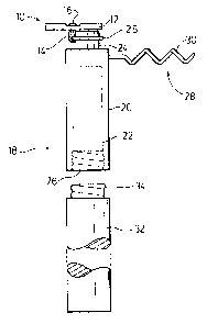
Figure 2 is a side elevation of the installation pole of the invention
operatively engaging the magnet anchor for elevating the anchor;
Figure 3 is a perspective view of the installation head shown in Figure 2;
Figure 4 is a side elevation of the said installation pole preparatory to
removing the magnet anchor from the ceiling strip; and
Figure 5 is a side elevation of an embodiment of installation pole having a
pair of magnet anchor suspension and removal means.
Description of the Preferred Embodiment
The magnet anchor 10 of the invention shown in an operative position attached
to

CA 02418633 2003-02-06
WO 02/15160 PCT/CA01/01151
-3-
a magnetic ceiling strip 11 in Figure 1 preferably comprises a rectangular
magnet body 12
with an elongated eye or tether 14 depending therefrom. Tether 14 preferably
is rivetted
to the centre of magnet by a rivet 16, shown more clearly in Fi~ures 2 and 4,
such that it
is free to rotate. A ring 15 fitted into tether 14 is adapted to receive an
object to be
supported by the magnet anchor such as a sign, banner, balloon or balloon
display.
The operative combination of magnet anchor 10 and installation pole 18 axe
illustrated in Figures 2 and 3. Installation pole 18 comprises an installation
head 20
formed of a non-magnetic material such as nylon plastic, wood or aluminum
alloy having
an elongated hollow cylindrical body 22 with a cylindrical lug 24 depending
from one end
and an internally threaded cavity 26 (shown by broken lines in Figure 2)
formed in the
opposite end. A hook 28, preferably in the shape of a corkscrew 30, is secured
to and
depends radially from body 22 in proximity to lug 24, shown more clearly in
Figure 3, for
reasons which will become apparently as the description proceeds. An elongated
wood,
plastic or metal pole extension 32 having a threaded end 34 adapted to mate in
snug
threaded engagement with threaded cavity 26 permits raising and lowering of
installation
head 20. Pole extension may also include a segmented pole having two or more
sections
with threaded connections or a telescopic pole well known in the art.
In operation, ring 15 having an obj ect to be suspended (not shown) attached
thereto
is fitted onto lug 24 as shown in Figure 2 with magnet anchor 12 resting on
the flat distal
end of lug 24. Lug 24 preferably is flattened by removal of a chord, as
depicted by
numeral 25 in Figure 3, to accommodate tether 14. The magnet anchor 10 with
attached
object is raised to a magnetic surface such as steel ceiling strip 11 by
elongated pole
extension 32 coupled to installation head 20. Upon contact of magnet anchor 10
to the
magnet strip 11, installation pole 18 is retracted.
To remove magnet anchor 10 from strip 11, the installation head 20 with
corkscrew hook 28 is raised by pole extension 32 and ring 15 engaged by
corkscrew 30,
as shown in Figure 4, to permit detachment of the magnet anchor 10.
Figure 5 illustrates another embodiment of the invention for multiple
installations
and removals of a plurality of magnet anchors with a single lift in which a
pair of
cylindrical lugs S0, 52 or a plurality of cylindrical lugs are mounted for
rotation in a
spaced-apart relation by mounting bolts 54, 56 on a lineax or arcuate support
bar 58.~

CA 02418633 2003-02-06
WO 02/15160 PCT/CA01/01151
-4-
Support bar 58 is mounted on an installation head 60 which is threadably
coupled at 62
to an extension pole 64. ,
Each of lugs 50, 52 has a radial corkscrew hook extension 68, 70 which can be
pivoted to an inoperative position such as depicted by corkscrew 68 when
lifting a magnet
anchor or can be pivoted to an operative position such as depicted by
corkscrew 70 when
engaging a magnet anchor ring for detaching and lowering the magnet anchor
from a
magnetic ceiling strip. Multiple installations with a single lift are
advantageous for
banners, swagging and signs requiring multiple, spaced-apart attachment
points.
It will be understood, of course that modifications can be made in the
embodiment
of the invention illustrated and described herein without departing from the
scope and
purview of the invention as defined by the appended claims.

Representative Drawing
A single figure which represents the drawing illustrating the invention.
Administrative Status

2024-08-01:As part of the Next Generation Patents (NGP) transition, the Canadian Patents Database (CPD) now contains a more detailed Event History, which replicates the Event Log of our new back-office solution.

Please note that "Inactive:" events refers to events no longer in use in our new back-office solution.

For a clearer understanding of the status of the application/patent presented on this page, the site Disclaimer , as well as the definitions for Patent , Event History , Maintenance Fee  and Payment History  should be consulted.

Event History

Description Date
Inactive: Expired (new Act pat) 2021-08-13
Change of Address or Method of Correspondence Request Received 2021-03-19
Revocation of Agent Request 2021-03-19
Appointment of Agent Request 2021-03-19
Common Representative Appointed 2019-10-30
Change of Address or Method of Correspondence Request Received 2018-01-16
Small Entity Declaration Determined Compliant 2008-06-10
Small Entity Declaration Request Received 2008-06-10
Grant by Issuance 2007-08-28
Inactive: Cover page published 2007-08-27
Pre-grant 2007-05-23
Inactive: Final fee received 2007-05-23
Inactive: IPC assigned 2006-12-04
Notice of Allowance is Issued 2006-12-04
Letter Sent 2006-12-04
Inactive: IPC removed 2006-11-30
Inactive: IPC assigned 2006-11-30
Inactive: Approved for allowance (AFA) 2006-11-10
Amendment Received - Voluntary Amendment 2006-06-13
Inactive: S.30(2) Rules - Examiner requisition 2005-12-13
Inactive: IPRP received 2004-05-10
Letter Sent 2003-12-23
Request for Examination Received 2003-12-08
Request for Examination Requirements Determined Compliant 2003-12-08
All Requirements for Examination Determined Compliant 2003-12-08
Inactive: Cover page published 2003-06-04
Inactive: Inventor deleted 2003-06-02
Inactive: Notice - National entry - No RFE 2003-06-02
Application Received - PCT 2003-03-10
National Entry Requirements Determined Compliant 2003-02-06
Small Entity Declaration Determined Compliant 2003-02-06
Application Published (Open to Public Inspection) 2002-02-21

Abandonment History

There is no abandonment history.

Maintenance Fee

The last payment was received on 2007-06-13

Note : If the full payment has not been received on or before the date indicated, a further fee may be required which may be one of the following

  • the reinstatement fee;
  • the late payment fee; or
  • additional fee to reverse deemed expiry.

Patent fees are adjusted on the 1st of January every year. The amounts above are the current amounts if received by December 31 of the current year.
Please refer to the CIPO Patent Fees web page to see all current fee amounts.

Fee History

Fee Type Anniversary Year Due Date Paid Date
Basic national fee - small 2003-02-06
MF (application, 2nd anniv.) - small 02 2003-08-13 2003-02-06
Request for examination - small 2003-12-08
MF (application, 3rd anniv.) - small 03 2004-08-13 2004-08-04
MF (application, 4th anniv.) - small 04 2005-08-15 2005-06-21
MF (application, 5th anniv.) - small 05 2006-08-14 2006-08-14
Final fee - small 2007-05-23
MF (application, 6th anniv.) - small 06 2007-08-13 2007-06-13
MF (patent, 7th anniv.) - small 2008-08-13 2008-07-09
MF (patent, 8th anniv.) - small 2009-08-13 2009-08-04
MF (patent, 9th anniv.) - small 2010-08-13 2010-08-09
MF (patent, 10th anniv.) - small 2011-08-15 2011-08-09
MF (patent, 11th anniv.) - small 2012-08-13 2012-08-03
MF (patent, 12th anniv.) - small 2013-08-13 2013-07-31
MF (patent, 13th anniv.) - small 2014-08-13 2014-07-15
MF (patent, 14th anniv.) - small 2015-08-13 2015-08-10
MF (patent, 15th anniv.) - small 2016-08-15 2016-07-19
MF (patent, 16th anniv.) - small 2017-08-14 2017-08-09
MF (patent, 17th anniv.) - small 2018-08-13 2018-08-10
MF (patent, 18th anniv.) - small 2019-08-13 2019-08-13
MF (patent, 19th anniv.) - small 2020-08-13 2020-07-07
Owners on Record

Note: Records showing the ownership history in alphabetical order.

Current Owners on Record
ROBINA B. BERNARD
Past Owners on Record
None
Past Owners that do not appear in the "Owners on Record" listing will appear in other documentation within the application.
Documents

To view selected files, please enter reCAPTCHA code :


To view images, click a link in the Document Description column. To download the documents, select one or more checkboxes in the first column and then click the "Download Selected in PDF format (Zip Archive)" or the "Download Selected as Single PDF" button.

List of published and non-published patent-specific documents on the CPD .

If you have any difficulty accessing content, you can call the Client Service Centre at 1-866-997-1936 or send them an e-mail at CIPO Client Service Centre.


Document
Description 
Date
(yyyy-mm-dd) 
Number of pages   Size of Image (KB) 
Drawings 2003-02-05 3 52
Description 2003-02-05 4 188
Claims 2003-02-05 2 84
Abstract 2003-02-05 1 56
Representative drawing 2003-02-05 1 8
Claims 2006-06-12 2 91
Representative drawing 2006-11-09 1 5
Notice of National Entry 2003-06-01 1 189
Acknowledgement of Request for Examination 2003-12-22 1 188
Commissioner's Notice - Application Found Allowable 2006-12-03 1 163
Maintenance fee payment 2018-08-09 1 26
PCT 2003-02-05 3 99
PCT 2003-02-06 2 83
PCT 2003-02-06 2 67
Correspondence 2007-05-22 2 49
Correspondence 2008-06-09 2 64
Fees 2009-08-03 1 31
Fees 2014-07-14 1 25
Maintenance fee payment 2019-08-12 1 26