Note: Descriptions are shown in the official language in which they were submitted.
CA 02418645 2003-02-10
WO 02/16069 PCT/US01/26422
-1-
METHOD AND APPARATUS FOR A COMBINED
MECHANICAL AND METALLURGICAL CONNECTION
BACKGROUND OF THE INVENTION
Field of the Invention
The present invention relates generally to a combined mechanical and
metallurgical
connection. More specifically, the present invention relates to a threaded
connection between
two conduits in which an amorphous diffusion bond is also made at the threaded
connection.
Description of the Related Arts
For purposes of this application, the present inventions will be described in
contrast with
mechanical and metallurgical connections that have been used in the oil and
gas exploration and
production industries. This background to which the present invention is
compared and
contrasted is not meant to limit the broad applicability of the inventions
disclosed herein in any
manner.
is The oil and gas industry is challenged with finding more oil and gas to
meet the ever-
increasing worldwide demand. As one example, offshore drilling operations are
commonly
occurring today in 7,000 feet of water compared to an average of about 2,000
feet merely ten
years ago. The cost to coinplete an offshore well increases exponentially with
working depth
and the tubular pipe required to complete a well remains the single largest
expenditure for
consumables.
It is common in the oil and gas exploration and production industries to use a
threaded
connection to join components, such as oilfield tubulars and pipes. Threaded
tubular connections
may be broadly categorized as coupling or non-coupling. Non-coupling
connections typically
cost less to manufacture and require less space downhole. However, such slim-
hole connections
typically are not as strong as the parent material, which they connect in
terms of tensile,
compressive and bending strength, or in the ability to seal against internal
or external pressure.
Various designs exist for threaded connections that meet established
performance characteristics.
For instance, threaded connections having substantially the same tensile
strength as the parent
material and substantially the same pressure capability as the parent material
have been
successfully designed. However, such connections always result in increased
outside diameter
compared to the parent conduit, which, therefore, requires a larger wellbore
and concomitant
increases in costs. Moreover, it is not uncommon for operators to require
"burst before leak"
CA 02418645 2008-07-07
= 2
performance from mechanical connections. Applicant is unaware of any
mechanical
connection having substantially the same geometry as the tubulars being joined
and
which also provides "burst before leak" performance.
When dimensional restrictions exist, threaded connections have been designed
that are able to join sections of conduit with very little change in
dimensions between
the conduit and the connection. Either internally or externally flush
connections are
available as well as connections that are both internally and externally
flush. However,
these flush connections always have a lower strength than the parent material.
The
strength (tensile, compressive, fatigue and/or bending) of these connections
can differ
as much as 50% or more from that of the conduits being joined, which greatly
limits
their use.
In contrast to mechanical connections, such as threaded joints, there exist
metallurgical connections, such as welded connections. Welded connections can
also
be fmished to be externally flush and may be substantially flush on the
internal
dimension if proper welding procedures are used. The strength and pressure
containment capability of these metallurgical connections can substantially
match those
of the conduit being joined. However, most welds cannot be performed in
environments where a danger of explosive gases exists. Also, welding requires
specially trained personnel and extensive non-destructive testing to insure
that a proper
weld is completed according to the welding specification. Further, traditional
welding
methods significantly (and often adversely) change the metallurgical, physical
and
corrosion resistance properties of the pipe in the weld and the heat affected
zone.
These changes cannot be fully removed or restored without full-scale heat
treatment.
Traditionally, welded connections have been limited to only the very upper
portions of
the string, which require the lowest strength and are, therefore, easier to
weld.
SUMMARY OF THE INVENTION
In accordance with one embodiment of the present invention, there is provided
a
method of joining tubular products comprising: providing a first tubular
having a
threaded end connection; providing a second tubular having a threaded end
connection
configured to make-up with the threaded end connection of the first tubular;
placing an
amount of amorphous diffusion bonding material on at least a portion of a
mating
surface of at least one of the tubulars; joining the first and second tubular
by making-up
the threaded end connections with a predetermined amount of torque so that the
amorphous diffusion bonding material is compressed by the mating surfaces; and
CA 02418645 2008-07-07
3
simultaneously applying heat to the threaded end connection joint sufficient
to cause
diffusion bonding among the bonding material and the first and second
tubulars.
In accordance with another embodiment of the present invention, there is
provided a combination mechanical and metallurgical connection comprising: a
first
component having a first portion of a mechanical connection; a second
component
having a second portion of a mechanical connection configured to form a
mechanical
connection in conjunction with the first portion; an amount of amorphous
diffusion
bonding material located on or adjacent at least one of the first and second
portions; the
first portion and the second portion connected together to form the mechanical
connection; and a metallurgical connection formed in combination with the
mechanical
connection through application of a predetermined amount of force to the
bonding
material and simultaneous application of heat to the bonding material, thereby
creating
an amorphous diffusion bond between at least the first and second components.
BRIEF DESCRIPTION OF THE DRAWINGS
The following figures, in conjunction with the written description, illustrate
at
least one preferred embodiment of the present invention, but do not limit the
applicability of the invention to only that shown.
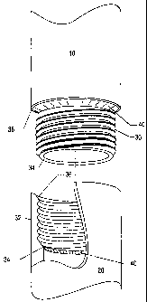
FIG. I illustrates a conventional internally and externally flush, tapered
thread
mechanical connection for conduits.
FIG. 2 illustrates a first embodiment according to the present invention.
FIG. 3 illustrates a second embodiment according to the present invention.
FIG. 4 illustrates a third embodiment according to the present invention.
FIG. 5A illustrates a fourth embodiment according to the present invention.
FIG. 5B illustrates the detail of part of the mating surface of FIG. 5A.
FIG 6 illustrates a cut-away detail of a combination mechanical/metallurgical
connection of the present invention.
DESCRIPTION OF ILLUSTRATIVE EMBODIMENTS
To illustrate the present inventions through contrast, a conventional, tapered
thread internally and externally flush connection is shown in FIG. 1. First
tubular 10
has a male (or pin) member 12, which is formed integrally at the end of the
conduit.
Second tubular 20 has an integral female (or box) member 22 that forms a
complimentary receptacle for the male member 12. First tubular 10 typically
has a
tapered thread, which refers to the external frusto-conical threaded end
connection 12
having an inner annular sealing surface 14 and outer annular sealing surface
16.
CA 02418645 2008-07-07
4
Second tubular 12 has an internal tapered thread, which refers to the frusto-
conical,
threaded end connection 22 having inner annular sealing surface 24 and outer
annular
sealing surface 26. The threaded connection illustrated in FIG. 1 is a
mechanical
connection that is machined on the pipe itself, which necessarily requires
removal of
parent material. This removal of load bearing material reduces the strength of
the
connection. The strength of this connection is lower than the strength of
either the first
or second tubular, 10 and 12.
The present invention is different than the mechanical connection illustrated
in
FIG. 1 insofar as additional strength and/or sealing ability is provided by an
additional
connection in the form of a metallurgical bond, preferably an amorphous
diffusion
bond (ADB) at or adjacent the mechanical connection. Amorphous diffusion
bonding
is a process that bonds two abutting/mating surfaces of a parent material
together.
According to the present invention, a bonding material with a lower melting
point than
either parent material is located between selected mating surfaces of the
mechanical
connection. By applying pressure and heating the bonding material to a
temperature
higher than its melting point, but lower than that of the parent material, a
slim profile
connection with no less strength and sealing ability than the adjacent parent
material
can be obtained.
The present invention can be implemented using a variety of mechanical
connections. For example, in the oil and gas exploration industry, the present
invention
can be used with oilfield tubulars having straight or cylindrical threads,
tapered threads,
various proprietary threads or other commonly available threads. With respect
to
tapered threads and most proprietary threads, those of skill in the art will
appreciate that
the joint relies on the mechanical connection to provide both strength and
sealing
properties. In contrast, the present invention can be implemented with non-
sealing and
sealing threads because the additional metallurgical connection created by the
diffusion
bond provides the additional strength and sealing abilities that are needed.
Thus, the
present invention has application to all manner of mechanical connections
where
connection strength, sealing ability and/or physical profile are important.
For example, the present invention can be implemented in highly stressed
mechanical connections in corrosive environments. Because most corrosion
mechanisms are accelerated at locations of high stress or residual energy, the
ADB
bond can be strategically positioned to effectively shield highly stressed
areas from the
CA 02418645 2008-07-07
corrosive environment or to reduce stress related corrosion as well as
providing
strength and sealing ability.
Further, conventional mechanical connections are subject to relaxation or
loosening over time caused by service-related vibrations. The combined
5 mechanical/metallurgical connection of the present invention is much less
susceptible,
if not immune, to this type of connection degradation. This property of the
present
invention can reduce or eliminate so-called "back-off' failures, which have
been linked
to contamination of ground water and other ecological disasters, as well as
exacting a
heavy toll on the economy.
The present invention can also reduce or eliminate the amount of thread
lubricant or "pipe dope" that has historically been used with mechanical
connections.
Most, if not all, of thread lubricants used today contain lead, zinc, copper
or other
environmentally unfriendly compounds. By creating the metallurgical bond of
the
present invention at the pressure surface, such as the inside diameter, the
connection
can be designed to eliminate the need for such lubricants. In addition to
addressing
several shortcomings of conventional mechanical connections, the present
invention
can be implemented to solve shortcomings of conventional metallurgical
connections,
such as welding. For example, some materials are notoriously difficult to
weld, such as
cast products. Also, welding dissimilar materials poses its own set of
problems. The
present invention can be used in place of conventional welding, thereby
eliminating any
shortcomings and expenses.
The following Figures 2 through 6 illustrate various implementations of the
present invention, but are not intended to limit in any manner the scope of
the claims
appended to the end of this application.
FIG. 2 illustrates a connection according to the present invention where
amorphous diffusion bonding (ADB) material (also known as amorphous metals or
metallic glass alloys) in the form of a ring or gasket 40 is applied to the
mechanical
connection. The mechanical connection illustrated in FIG. 2 is a conventional
non-
sealing thread (eg., straight or cylindrical threads) joint having a pin end
30 and a box
end 32. This connection also has inner and outer abutting surfaces, 34 and 36,
respectively. As shown in FIG. 2, the ADB material in the form of a ring or
gasket 40
can be located on the inner abutting surface 34 of the box end 32, on the
outer abutting
surface 36 of the pin end 30, or on both surfaces. While it is typical for the
material of
CA 02418645 2008-07-07
6
the first and second tubulars to be substantially identical, the present
invention can be
used to join dissimilar materials as well.
For example, the present invention can be implemented on a collar-type
mechanical connection (not shown) comprising two externally threaded (male)
components and an internally threaded collar. As is conventional in the art,
the collar is
used to join the two male components in typically fluid tight engagement. In
corrosive
environments, the collar is typically required to be made from the same
corrosion-
resistant material from which the male components are made. For internal
corrosive
environments, however, the present invention permits the collar to be made
from a less
expensive material (such as carbon steel) because the metallurgical bond of
the present
invention can be strategically located at the internal surfaces to effectively
shield the
collar from the corrosive environment.
Returning to FIG. 2, it is preferred that the bonding surfaces (in this case
surfaces 34 and 36) be cleaned to remove any oils, dirt or oxides. Machining,
electrochemical machining or electro-discharge machining or other known
machining
operations may accomplish such cleaning. Also, cleaning with a chemical such
as
acetone may also be used to remove oil and dirt from the mating surfaces.
Preparation
of the mating surfaces to remove oxide layers, oil or dirt can help to
strengthen the
resulting bond between joined materials.
After preparation of the mating surfaces, the bonding material may be applied
to
or positioned on or adjacent the mechanical connection. The ADB materia140 may
be
held in place with a binder (not shown) or by electrostatic attraction or any
other means
that doesn't interfere with the resulting bond. The ADB material preferably
used for
connecting oilfield tubulars is an iron-based alloy that is similar to the
parent material
of the connectors and is typically 25 to 100 microns thick. One such supplier
of ADB
materials suitable for use with this invention is the Allied Signal division
of Honeywell,
which supplies ADB material under the MetGlass brand. A melting point
depressant or
flux may be added to the bonding material. Some conventional melting point
depressant materials include boron or silicon. As a result of threading the
pin 30 into
the box 32, the ADB material 40 becomes sandwiched between the abutting
portions of
the first and second tubulars, 10 and 20 and the tubulars are automatically
aligned for
bonding.
FIG. 3 illustrates the application of ADB material to conventional tapered
thread mechanical connection. However, in contrast to FIG. 2, the ADB material
is
CA 02418645 2008-07-07
7
present in the form of buttons or islands 42 instead of the ring 40 of FIG. 2.
FIG. 4
shows an additional embodiment of the application of ADB material according to
the
present invention. Sputter deposition techniques may be used to coat the
desired
mating surfaces with bonding material. Sputter deposition involves known
techniques
for applying a substantially uniform thickness of bonding material andlor
melting point
depressant on the mating surfaces. As seen in FIG. 4 sputter deposits 44 may
be placed
on the inner annular sealing surface 14 of first tubular 10. Sputter deposits
44 may also
be placed on the inner annular sealing surface 24 of second tubular 20.
Alternatively,
ADB material may be deposited on virtually any abutting surface of the
mechanical
connector.
As a result of connecting the male and female conduits, sputter deposits 44
become sandwiched between the parent material of inner annular sealing
surfaces 14
and 26. Sputter deposits 44 become sandwiched between the parent material of
annular
sealing surfaces 16 and 24. Due to the similarities between the use of powders
and
sputter deposits as bonding material, description of the application of
powders with or
without binding agent is omitted as being redundant to the previous sputter
deposition
description.
FIG. 5A shows an additional embodiment of the application of bonding material
according to the present invention. Bonding material in the form of sputter
deposits is
applied to mechanical threads 18 and 28. FIG. 5B shows a detail of the
threaded end
connection of the fust tubular. Known techniques of sputter deposition are
used to
apply the bonding material with or without melting point depressant to the
thread. In
the present embodiment, sputter deposits 48 are located in the valleys 38 of
the thread,
and sputter deposits 50 are located on the leading flanks 39 of the thread. A
shield (not
shown) may be used as part of the sputter deposition technique to limit the
placement
of the bonding material. Bonding material need not be placed solely on the
surfaces of
the thread shown in the present Figure. Bonding material may also be applied
to other
abutting surfaces of the threaded end connection.
With bonding material applied to the mechanical connection, such as in one of
the previously described fashions, the connection of the present invention is
then
formed. To make up the connection, threaded end connections 12 or 30 and 22 or
32
are screwed together until the appropriate surfaces abut. FIG. .6 depicts a
connection of
the pin 30 and box 32 of the fust and second tubulars 10 and 20. The threads
of the
threaded end connections are integrally meshed as the tubulars are screwed
together
CA 02418645 2008-07-07
8
and the ADB material 48 flows into position in and around the abutting and
interfering
surfaces.
Axial and radial compressive forces result from screwing the members tightly
together. The desired location for the bonding material as noted previously is
in those
areas where there is abutment between surfaces of the mechanical connection.
Further
tightening of the connection will cause the locations of abutment to be loaded
progressively. Application of torque when the surfaces are in abutment
provides the
required pressure load to facilitate the amorphous diffusion bonding process.
The
pressure applied may also be used to break any undesirable oxide layers that
may be
present at the bonding interface.
With the loading applied to the ADB material, energy in the form of heat is
simultaneously applied to the connection joint adjacent the ADB material for a
predetermined period of time. Induction, electric resistance, microwave,
infrared or the
like may accomplish the required heating. In a preferred embodiment for the
connection shown in FIG. 2, two induction heating coils (not shown), each one
adjacent
an area of ADB material (at 34 and 36) are used to heat the connection. During
the
application of heat to the joint, the pressure or load may be maintained,
decreased or
increased as desired. The pressure also uniformly distributes the liquefied
bonding
material in the joint, resulting in the thickness of the bond to be minimized.
During the heating process, the parent material is not adversely affected by
the
heating conditions, such as occurs in conventional welding. With the present
invention,
only a minimal heat affected zone (HAZ) or metallurgical discontinuity is
created. As
the ADB material diffuses into the parent material, solidification occurs such
that an
amorphous diffusion bond forms between the abutted surfaces or interference
fits the
connection. The resulting connection with amorphous diffusion bond is
substantially
stronger than the conventional flush mechanical connection joint. Diffusion of
the
ADB material may be accomplished in a inert or reactive environment, depending
upon
the characteristics of the diffusion bond being created.
It will be appreciated by those of skill having benefit of this disclosure of
the
synergistic relationship between a threaded mechanical connection and the
diffusion
process. The threaded connection provides automatic alignment and control of
the
abutting surfaces during the diffusion process. Further, the threaded
connection allows
the operator to fairly precisely control the application of load to the
abutting surfaces
during diffusion. For example, as heat is applied to the joint of the present
invention,
CA 02418645 2008-07-07
9
thermal expansion may increase or change the load conditions at the abutting
surfaces.
The operator can adjust the load at the abutting surfaces (and, therefore, on
the ADB
material) by adjusting the torque on the mechanical connection. Thus, the
present
invention obviates expensive and bulky alignment jigs and devices typically
necessary
for creating high quality diffusion bonds.
It will now be appreciated by those of ordinary skill having the benefit of
this
disclosure that a combination mechanical/metallurgical connection of the form
described herein can provide a connection or joint between members, such as
conduits,
in which the overall dimensions of the connection are substantially the same
as the
members joined. Further, this connection provides the strength and sealing
abilities
necessary for the most demanding applications. The connection designer will
appreciate the flexibility offered by the present invention in locating the
ADB bond at
virtually any location in the connection. The designer, therefore, can locate
the sealing
effects of the ADB bond at the most preferred location and separately or
concomitantly
locate the strength and/or corrosion shielding effects of the ADB bond at the
most
preferred locations. The present invention allows the designer to enhance the
resulting
connection's overall performance, such as by enhancing the fatigue life of the
connection.
Although the present invention has been illustrated in the context of oilfield
tubulars having a pin and a box, it will be appreciated that the present
invention may be
applied as described to connections utilizing sleeve couplings, or clamps and
other
energizing devices. Further, the present invention may be used with today's
expandable tubular technology in which oilfield tubulars are placed downhole
then a
specifically designed pig or mandrel is used to expand the tubular string.
Connections
made according to the present invention are particularly suited for such
service because
of the strength, sealing and dimensional attributes described above. However,
the
application of the present invention is not limited to the oilfield industry
or to the
connection of one conduit to another. The present invention may be utilized
anywhere
a conventional mechanical connection or a conventional metallurgical
connection has
been heretofore used.
The foregoing descriptions of the various embodiments of present invention
present a number of advantages over the prior art. Various modifications and
variations
can be made without departing from the scope of the present invention, as set
forth in
the accompanying claims.