Language selection

Search

Patent 2418682 Summary

Third-party information liability

Some of the information on this Web page has been provided by external sources. The Government of Canada is not responsible for the accuracy, reliability or currency of the information supplied by external sources. Users wishing to rely upon this information should consult directly with the source of the information. Content provided by external sources is not subject to official languages, privacy and accessibility requirements.

Claims and Abstract availability

Any discrepancies in the text and image of the Claims and Abstract are due to differing posting times. Text of the Claims and Abstract are posted:

  • At the time the application is open to public inspection;
  • At the time of issue of the patent (grant).
(12) Patent: (11) CA 2418682
(54) English Title: METHOD FOR EVENING TENSION IN A TWISTED PAIR ELECTRIC CABLE
(54) French Title: METHODE D'EGALISATION DE LA TRACTION DANS UN CABLE ELECTRIQUE A PAIRE TORSADEE
Status: Expired and beyond the Period of Reversal
Bibliographic Data
(51) International Patent Classification (IPC):
  • H02G 01/02 (2006.01)
  • H02G 07/02 (2006.01)
  • H02G 07/04 (2006.01)
(72) Inventors :
  • SMITH, CHAD R. (United States of America)
(73) Owners :
  • GENERAL CABLE TECHNOLOGIES CORPORATION
(71) Applicants :
  • GENERAL CABLE TECHNOLOGIES CORPORATION (United States of America)
(74) Agent: SMART & BIGGAR LP
(74) Associate agent:
(45) Issued: 2012-06-26
(22) Filed Date: 2003-02-07
(41) Open to Public Inspection: 2003-08-08
Examination requested: 2008-01-24
Availability of licence: N/A
Dedicated to the Public: N/A
(25) Language of filing: English

Patent Cooperation Treaty (PCT): No

(30) Application Priority Data:
Application No. Country/Territory Date
10/067,849 (United States of America) 2002-02-08

Abstracts

English Abstract

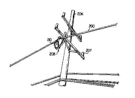
A method of evening the tension in the conductors of a twisted pair electric cable during the cable's installation comprising the step of pulling the cable through stringing rollers while attached to a tension evening device. That allows constant adjustment of the tension in each of the cable's conductors, which prevents an unwanted looping effect and eliminates the need to even the tension at the end of the installation process. The tension evening device comprises a pull rope attached to a swivel that holds a sheave. The device is sized small enough so that it fits through the stringing rollers such that, during the installation of the cable, the entire tension evening device is pulled through. The sheave includes a groove around its outside diameter in which a sheave rope is placed. The ends of the sheave rope are attached to an end of each conductor. The tension in the conductors is maintained by the sheave and sheave rope which rotate in response to the tension or force applied by the conductors, providing greater slack to the higher tensioned conductor and exerting a greater pulling force on the lower tensioned conductor.


French Abstract

Une méthode d'égalisation de la tension dans les conducteurs d'un câble électrique à paire torsadée lors de l'installation du câble comprenant l'étape consistant à tirer le câble à travers des rouleaux de déroulage alors qu'il est connecté à un dispositif d'égalisation de tension. Cela permet un ajustement constant de la tension dans chacun des conducteurs du câble, ce qui empêche un effet de boucle indésirable et élimine la nécessité d'égaliser la tension à la fin du processus d'installation. Le dispositif d'égalisation de tension comprend un câble de traction attaché à un émerillon qui retient une poulie. Le dispositif est dimensionné suffisamment petit pour qu'il passe à travers les rouleaux de déroulage de telle sorte que, lors de l'installation du câble, le dispositif d'égalisation de tension au complet est tiré à travers celui-ci. La poulie comprend une gorge autour de son diamètre extérieur, dans laquelle une corde de poulie est placée. Les extrémités de la corde de poulie sont fixées à une extrémité de chaque conducteur. La tension dans les conducteurs est maintenue par la poulie et la corde de poulie qui tournent en réponse à la tension ou la force appliquée par les conducteurs, fournissant plus de mou au conducteur plus tendu et exerçant une plus grande force de traction sur le conducteur moins tendu.

Claims

Note: Claims are shown in the official language in which they were submitted.


CLAIMS:
1. A method of evening tension in at least two conductors of a twisted pair
electric
cable comprising the steps of:
providing a tension evening device sized to fit within a support block on a
power
pole;
attaching the twisted pair electric cable to the tension evening device; and
pulling the tension evening device through the support block on the power pole
whereby the tension evening device equalizes the tension in the more than one
conductor.
2. The method of evening the tension in the conductors of a twisted pair
electric cable
of claim 1, wherein:
the tension evening device comprises a swivel, a clevis and a sheave.
3. The method of evening the tension in the conductors of a twisted pair
electric cable
of claim 2, wherein:
the sheave has a groove for the placement of a sheave rope, and the sheave
rope has
two ends, each attached to a separate conductor of the electric cable.
4. The method of evening the tension in the conductors of a twisted pair
electric cable
of claim 2, wherein:
the swivel, the clevis and the sheave are a single component.
5. The method of evening the tension in the conductors of a twisted pair
electric cable
of claim 1, wherein:
8

the step of pulling the tension evening device through the support block
rotates the
sheave and sheave rope so that it provides greater slack to a higher tensioned
conductor and
exerts a greater pulling force on a lesser tensioned conductor thereby
equalizing the tension
in the conductors.
6. A tension evening device for maintaining an equal tension in at least two
conductors
of a twisted pair electric cable during its installation comprising:
a swivel, a clevis and a sheave; wherein
the sheave has a groove around its outside surface for placing a sheave rope
therein,
the sheave and sheave rope rotating to equalize the tension in the conductors
of the electric
cable, and wherein the tension evening device is sized to fit within a support
block on a
power pole.
7. The tension evening device of claim 6, wherein:
the swivel, the clevis and the sheave is a single component.
8. The tension evening device of claim 6, wherein:
the sheave is rotatable so its position is independent of the other parts of
the tension
evening device.
9

Description

Note: Descriptions are shown in the official language in which they were submitted.


CA 02418682 2003-02-07
METHOD FOR EVENING TENSION IN A
TWISTED PAIR ELECTRIC CABLE
Field of Invention
The present invention is directed to a method for evening the tension in the
two
conductors of a twisted pair (T-2) electric cable during its installation,
preventing one
conductor from becoming slack and looping around the other conductor and
decreasing the
cable's stability.
Background of the Invention
Twisted pair (T-2) electric cables have been in use since the early 1970's,
with
thousands of miles of cable being installed since that time. The T-2 cable
comprises two
electrical conductors that are joined in a gradual twist about every 9 feet.
The cable is
twisted to combat wind induced motion, such as Aeolian vibration, galloping
and sub-
conductor oscillation, which can damage the cable's insulators and hangers.
Aeolian vibration is caused by low to moderate winds which create vortices
around
the electric cable, causing it to vibrate up and down. Galloping occurs when
an airflow
around a cable produces lift forces that cause it to move up and down in a
wavelike motion,
That is especially problematic when ice builds up on the front of an electric
cable, creating an
air-foil shape and increasing the wind induced lift forces acting on the
cable. Sub-conductor
oscillation occurs in non-twisted electric cable pairs where a. front
conductor takes the brunt
force of the wind and casts a wind-shadow on a second conductor trailing the
first, causing
the second conductor to vibrate in an elliptical motion with respect to the
first.
The twist in the T-2 cable resists the wind induced motion by constantly
varying the
diameter of the electric cable, preventing the build-up of resonant vibration,
and producing a
low torsional stiffness in the cable.
1

CA 02418682 2003-02-07
However, for the electric cable twist to remain constant and effective, it is
important
that equal tension in the two conductors of the cable be maintained. Uneven
tension in the
conductors can cause a looping or sagging effect, where one conductor loops
around the
other, causing a single conductor to bear the weight of both. That increases
the likelihood
that the electric cable will detach from a power pole, or otherwise makes the
cable unstable.
Currently, an even tension is achieved in the T-2 cable by pre-twisting the
conductors
and binding them together using a metal band. The cable is then pulled through
stringing
rollers located on power poles to set up the cable for attachment to the power
pole. However
during this process the tension in the cables may become uneven. That can be
caused by
having stringing rollers that are too small or having an angle of approach
that is too steep.
Both these features can cause the roller to "pinch" the cable and push the
twist back., thereby
unevening the tension in the cable. To correct that problem, the cable is
attached to a snatch
block that evens the tension in the conductors after being pulled through the
stringing rollers.
Summary and Objects of the Invention
The present invention is directed to a method of evening the tension in the
conductors
of a twisted pair electric cable having the step of pulling the cable through
stringing rollers
while attached to a tension evening device. That allows constant adjustment to
the tension in
each of the conductors during its installation, preventing a looping effect
and eliminating the
need to even the tension at the end of the installation process.
The tension evening device has a pull rope attached to a swivel that holds a
sheave.
The sheave has a groove around its outside diameter in which a sheave rope is
placed. The
ends of the sheave rope are attached to an end of each conductor. The tension
in the
conductors is maintained by the sheave and sheave rope which rotate in
response to the
tension or force applied by the conductors, providing greater slack to the
higher tensioned
conductor and exerting a greater pulling force on the lower tensioned
conductor.
2

CA 02418682 2003-02-07
Additionally, the tension evening device is sized small enough so that it fits
through the
stringing rollers so that during the installation of the cable, the entire
tension evening device
is pulled through.
It is therefore an object of the present invention to provide a method of
maintaining
an even tension in a T-2 cable to prevent one of the conductors from looping
around the
other. It is a further object of the present invention to provide a method of
maintaining an
even tension during the cable's installation process to eliminate the
additional step of evening
the tension after the cable is pulled through the stringing rollers.
Brief Description of the Drawings
FIG. 1A is a drawing which shows an end view of an airflow around an electric
cable
causing Aeolian vibration;
FIG. lB is a drawing which shows a side view of the electric cable of FIG. 1A
undergoing Aeolian vibration;
FIGS. 2A is a drawing which shows an end view of an airflow around an electric
cable with ice buildup causing galloping;
FIG. 2B is a drawing which shows a side view of two electric cable of FIG. 2A
undergoing galloping;
FIG. 3A is a drawing which shows end view of an airflow around a non-twisted
pair
electric cable causing sub-conductor oscillation;
FIG. 3B is a drawing which shows a side view of the non-twisted pair electric
cable
of FIG. 3A undergoing sub-conductor oscillation;
FIG. 4A is a drawing which shows a side view of a twisted pair electric cable;
FIG. 4B is a drawing which shows an end view of the twisted pair electric
cable of
FIG. 4A;
3

CA 02418682 2003-02-07
FIG. 5 is a drawing which shows a power pole with a twisted pair electric
cable
attached;
FIG. 6 is a drawing which shows a prior art tension evening device;
FIG. 7A is a drawing which shows a top view of a tension evening device of the
present invention;
FIG. 7B is a drawing which shows a side view of the tension evening device of
FIG.
7A; and
FIGS. 8A and 8B are drawings which shows a second embodiment of a tension
evening device of the present invention.
Detailed Description of the Invention
Wind induced motion in electric cables can damage the cable's insulators and
hangers, making it vulnerable to failure. Examples of wind induced motion in
cables are
shown in FIGS. 1-3. FIGS. IA and IB show an electric cable 100 undergoing
Aeolian
vibration. FIG. IA shows an airflow 102 moving past the cable 100, creating
small vortices
and causing it to move in small up and down motions (shown in dotted lines).
FIG. 1B
shows the effect of the vibration on the cable 100 attached to a power pole
104. FIGS. 2A
and 2B show an electric cable 100 undergoing a galloping effect. FIG. 2A shows
the
conductor 100 with ice 106 formed on its front surface and an airflow 102
moving past the
cable. The airflow 102 produces a lift effect, which is heightened by the ice
buildup 106,
causing the cable 100 to sway up and down in a wavelike motion between the two
power
poles 104, as shown in FIG. 2B. FIGS. 3A and 3B show an electric cable 100
undergoing
sub-conductor oscillation. The electric cable in this case has a front
conductor 107 and a rear
conductor 108 that are connected by a spacer 110. FIG. 3A shows an airflow 102
moving
past the front conductor 107, creating a turbulent wake field that causes the
rear conductor
108 to move in a circular motion about the front conductor 107, as shown in
FIG. 3B.
4

CA 02418682 2011-08-02
Twisted pair (T-2) electric cables 200 are known and have been installed on
power poles to combat these wind induced motions. FIGS. 4A and 4B show a side
view and an end view of the T-2 electric cable 200, respectively. The cable
200 is
made up of two conductors 202 and 204 that are twisted along its length. FIG.
4A
shows the side view of the cable 200, and an end view at various points along
its
length. FIG. 4B shows an end view of the cable 200 similar to the end view
shown
in FIG. 4A, but with the changing diameter of the cable shown in dotted lines.
The
constant changing diameter of the cable helps to combat wind effects by
stiffening
the cable and preventing resonant vibration from building up.
FIG. 5 shows a power pole 206 with a stringing roller 208 used to install T-2
cables. Typically, the T-2 cable 200 is installed on the power pole 206 by
initially
twisting the cable 200 and then pulling it through the stringing roller 208.
After the
cable 200 is pulled through, it is permanently affixed to the power pole 206
at the
insulators 207. However, during the "pulling through" process, oftentimes the
twist
in the cable 200 becomes non-uniform. That can be caused by too small a wheel
210
in the stringing roller 208 which can "pinch" the cable 200 and not allow it
to pass
freely through. The twist in the cable is then pushed back, so that the cable
is
twisted tighter prior to the stringing roller 208 than after it. Additionally,
too sharp
an entry angle into the wheel 210 aggravates that problem, pushing the twist
back
further.
Any uneven twist or tension in the cable 200 is corrected by using a chain
hoist 211 and snatch block 212, as shown in FIG. 6, to even the tension in the
T-2
cable after it is pulled through the stringing rollers 208. The snatch block
212
consists of a sheave 213 having a groove around its outside surface. A sheave
rope
214 is placed within the groove, with each end of the rope being attached to
one of
the two conductors 216 and 218 of the T-2 cable using a first grip 220 and a
second
grip 222. A pull rope 224 then pulls the snatch block 212 causing the sheave
213
and the sheave rope 214 to rotate in the direction of the
5

CA 02418682 2003-02-07
higher tensioned conductor. That rotation provides greater slack to the
conductor having
more tension, and conversely, exerts a greater pulling force on the conductor
with less
tension, thereby equalizing the tension in the two conductors. After the cable
tensioned is
evened, it is attached or deadended to the insulator 207 on the power pole
202.
In the process described above, the cable tension is evened after it has been
pulled
through the stringing roller 208 because the snatch block 212 is too large to
pass through the
wheel 210 in the stringing roller 208.
The apparatus and method of the present invention is directed to a tension
evening
device 300 that is small enough to fit within the groove of the wheel 210 on
the stringing
roller 208. The tension evening device 300, shown in FIGS. 7A and 7B, allows
the T-2 cable
313 to be installed while maintaining an even tension in each of the two
conductors 312 and
314. It eliminates the step of having to even the tension at the end of the
installation process.
The tension evening device 300 of the present invention is similar to the
snatch block 212 of
the prior art, comprising a swivel 302, a connector link 304, a clevis 306 and
a sheave 308.
The sheave 308 has a groove 30!) around its outer surface into which a sheave
rope 310 is
placed. The rope's two ends are then attached to the ends oftwo conductors 312
and 314. In
that way when the pull rope is pulled through a stringing roller on the power
pole 206, the
sheave 308 and the sheave rope 310 rotate to equalize the tension in the
conductors 312 and
314. And, because the tension evening device 300 is small enough to fit within
the wheel
210 of the stringing roller 208, a constant tension is maintained in the T-2
cable 313 at all
times.
FIGS. 8A and 8B show a second embodiment of the invention. In this embodiment,
a
swivel, a connector link, a clevis and a sheave have been combined so that the
tension
evening device 400 is made from a single component. The pull rope 316 is
inserted through
the opening 402 in a first end of the device 400. This first end is rotatable
relative to a
6

CA 02418682 2003-02-07
second end of the device about the swivel line 404. The second end of the
device includes a
sheave 406 having a groove 408 around its outside surface. A sheave rope is
placed. in the
groove 408 and is attached to the ends of the conductors 312 and 314 of the T-
2 cable 313.
As the pull rope 316 is pulled, the sheave 406 and sheave rope (not shown)
rotate to equalize
the tension in the conductors as discussed above.
Although certain presently preferred embodiments of the present invention have
been
specifically described herein, it will be apparent to those skilled in the art
to which the
invention pertains that variations and modifications of the various
embodiments shown and
described herein may be made without departing from the spirit and scope of
the invention.
Accordingly, it is intended that the invention be limited only to the extent
required by the
appended claims and the applicable rules of law.
7

Representative Drawing
A single figure which represents the drawing illustrating the invention.
Administrative Status

2024-08-01:As part of the Next Generation Patents (NGP) transition, the Canadian Patents Database (CPD) now contains a more detailed Event History, which replicates the Event Log of our new back-office solution.

Please note that "Inactive:" events refers to events no longer in use in our new back-office solution.

For a clearer understanding of the status of the application/patent presented on this page, the site Disclaimer , as well as the definitions for Patent , Event History , Maintenance Fee  and Payment History  should be consulted.

Event History

Description Date
Time Limit for Reversal Expired 2021-08-31
Inactive: COVID 19 Update DDT19/20 Reinstatement Period End Date 2021-03-13
Letter Sent 2021-02-08
Letter Sent 2020-08-31
Inactive: COVID 19 - Deadline extended 2020-08-19
Inactive: COVID 19 - Deadline extended 2020-08-06
Inactive: COVID 19 - Deadline extended 2020-07-16
Letter Sent 2020-02-07
Common Representative Appointed 2019-10-30
Change of Address or Method of Correspondence Request Received 2018-01-12
Grant by Issuance 2012-06-26
Inactive: Cover page published 2012-06-25
Pre-grant 2012-04-12
Inactive: Final fee received 2012-04-12
Notice of Allowance is Issued 2012-03-09
Letter Sent 2012-03-09
Notice of Allowance is Issued 2012-03-09
Inactive: Approved for allowance (AFA) 2012-02-29
Letter Sent 2011-08-26
Amendment Received - Voluntary Amendment 2011-08-02
Inactive: S.30(2) Rules - Examiner requisition 2011-02-10
Letter Sent 2009-08-07
Reinstatement Requirements Deemed Compliant for All Abandonment Reasons 2009-07-16
Deemed Abandoned - Failure to Respond to Maintenance Fee Notice 2009-02-09
Letter Sent 2008-04-10
All Requirements for Examination Determined Compliant 2008-01-24
Request for Examination Requirements Determined Compliant 2008-01-24
Request for Examination Received 2008-01-24
Inactive: IPC from MCD 2006-03-12
Application Published (Open to Public Inspection) 2003-08-08
Inactive: Cover page published 2003-08-07
Inactive: IPC assigned 2003-05-22
Amendment Received - Voluntary Amendment 2003-05-06
Inactive: First IPC assigned 2003-04-02
Inactive: Filing certificate - No RFE (English) 2003-03-11
Letter Sent 2003-03-11
Application Received - Regular National 2003-03-11

Abandonment History

Abandonment Date Reason Reinstatement Date
2009-02-09

Maintenance Fee

The last payment was received on 2011-12-12

Note : If the full payment has not been received on or before the date indicated, a further fee may be required which may be one of the following

  • the reinstatement fee;
  • the late payment fee; or
  • additional fee to reverse deemed expiry.

Patent fees are adjusted on the 1st of January every year. The amounts above are the current amounts if received by December 31 of the current year.
Please refer to the CIPO Patent Fees web page to see all current fee amounts.

Owners on Record

Note: Records showing the ownership history in alphabetical order.

Current Owners on Record
GENERAL CABLE TECHNOLOGIES CORPORATION
Past Owners on Record
CHAD R. SMITH
Past Owners that do not appear in the "Owners on Record" listing will appear in other documentation within the application.
Documents

To view selected files, please enter reCAPTCHA code :


To view images, click a link in the Document Description column. To download the documents, select one or more checkboxes in the first column and then click the "Download Selected in PDF format (Zip Archive)" or the "Download Selected as Single PDF" button.

List of published and non-published patent-specific documents on the CPD .

If you have any difficulty accessing content, you can call the Client Service Centre at 1-866-997-1936 or send them an e-mail at CIPO Client Service Centre.


Document
Description 
Date
(yyyy-mm-dd) 
Number of pages   Size of Image (KB) 
Drawings 2003-02-06 8 619
Description 2003-02-06 7 341
Abstract 2003-02-06 1 32
Claims 2003-02-06 2 57
Representative drawing 2003-04-01 1 192
Drawings 2003-05-05 6 144
Description 2011-08-01 7 334
Drawings 2011-08-01 6 136
Claims 2011-08-01 2 52
Representative drawing 2012-05-28 1 15
Courtesy - Certificate of registration (related document(s)) 2003-03-10 1 130
Filing Certificate (English) 2003-03-10 1 169
Reminder of maintenance fee due 2004-10-11 1 110
Reminder - Request for Examination 2007-10-09 1 127
Acknowledgement of Request for Examination 2008-04-09 1 177
Courtesy - Abandonment Letter (Maintenance Fee) 2009-04-05 1 172
Notice of Reinstatement 2009-08-06 1 163
Commissioner's Notice - Application Found Allowable 2012-03-08 1 162
Commissioner's Notice - Maintenance Fee for a Patent Not Paid 2020-03-31 1 545
Courtesy - Patent Term Deemed Expired 2020-09-20 1 551
Commissioner's Notice - Maintenance Fee for a Patent Not Paid 2021-03-28 1 536
Fees 2004-12-16 1 28
Fees 2005-12-14 1 27
Fees 2006-12-19 1 29
Fees 2007-12-16 1 29
Fees 2009-07-15 1 36
Fees 2009-12-15 1 35
Fees 2010-12-14 1 37
Correspondence 2011-08-25 1 19
Correspondence 2011-10-31 1 13
Correspondence 2012-04-11 1 50