Language selection

Search

Patent 2418825 Summary

Third-party information liability

Some of the information on this Web page has been provided by external sources. The Government of Canada is not responsible for the accuracy, reliability or currency of the information supplied by external sources. Users wishing to rely upon this information should consult directly with the source of the information. Content provided by external sources is not subject to official languages, privacy and accessibility requirements.

Claims and Abstract availability

Any discrepancies in the text and image of the Claims and Abstract are due to differing posting times. Text of the Claims and Abstract are posted:

  • At the time the application is open to public inspection;
  • At the time of issue of the patent (grant).
(12) Patent: (11) CA 2418825
(54) English Title: LATCHING ELECTRIC-CONTROL VEHICLE AIR BRAKE SYSTEM
(54) French Title: SYSTEME DE FREINS PNEUMATIQUES DE VEHICULE A COMMANDE ELECTRIQUE DE VERROUILLAGE
Status: Expired
Bibliographic Data
(51) International Patent Classification (IPC):
  • B60T 13/66 (2006.01)
  • B60R 16/02 (2006.01)
  • B60T 17/06 (2006.01)
  • B60T 17/08 (2006.01)
(72) Inventors :
  • EBERLING, CHARLES E. (United States of America)
(73) Owners :
  • BENDIX COMMERCIAL VEHICLE SYSTEMS LLC (United States of America)
(71) Applicants :
  • BENDIX COMMERCIAL VEHICLE SYSTEMS LLC (United States of America)
(74) Agent: MACRAE & CO.
(74) Associate agent:
(45) Issued: 2009-08-25
(86) PCT Filing Date: 2001-09-19
(87) Open to Public Inspection: 2002-03-28
Examination requested: 2006-06-20
Availability of licence: N/A
(25) Language of filing: English

Patent Cooperation Treaty (PCT): Yes
(86) PCT Filing Number: PCT/US2001/029142
(87) International Publication Number: WO2002/024504
(85) National Entry: 2003-02-21

(30) Application Priority Data:
Application No. Country/Territory Date
09/667,368 United States of America 2000-09-22

Abstracts

English Abstract


An electric control valve for a heavy duty vehicle air parking brake system.
The system uses latching electrically controlled solenoid air valves (22) to
control the parking brake systems of the tractor and trailer. The system
allows electric control devices (30) to be placed in the vehicle's instrument
panel. The system maintains a previously set state of the system even in the
event of a loss of electrical power to the controller. Indicator lamps (28)
provide park status information to the vehicle driver.


French Abstract

L'invention porte sur une soupape à commande électrique pour système de frein de parc pneumatique de véhicules lourds, et sur un système utilisant des soupapes (22) électropneumatiques de verrouillage montées sur le véhicule tracteur et sur la remorque. Les commandes électriques (30) du système peuvent se placer dans le tableau de bord. Le système reste dans l'état fixé antérieurement même en cas de défaut d'alimentation électrique du contrôleur. Des témoins lumineux (28) renseignent le chauffeur sur l'état des freins de parc.

Claims

Note: Claims are shown in the official language in which they were submitted.


CLAIMS

What Is Claimed Is:

1. A parking brake controller for a vehicle equipped with air parking
brakes for a tractor and a trailer, of the type having a reservoir of air
pressure and
wherein said air parking brakes are deactivated upon application of air
pressure to
said air parking brakes, and activated upon a loss of air pressure to said air
parking
brakes, comprising:
a first latching solenoid air valve capable of being set in a first
position for applying air pressure to said tractor air parking brake, and
capable of
being set in a second position for venting said tractor air parking brake to
atmosphere
thereby activating said tractor air parking brake;
a second latching solenoid air valve capable of being set in a first
position for applying air pressure to said trailer air parking brake, and
capable of being
set in a second position for venting said trailer air parking brake to
atmosphere thereby
activating said trailer air parking brake; and
a control circuit controlled by at least one electrical switch capable of
sending control signals to said first and second latching solenoid air valves
for moving
said latching solenoid air valves selectively between either of said first or
second
positions.

2. The parking brake controller for a vehicle according to Claim 1
further comprising a first low air pressure switch capable of detecting a
predetermined
low air pressure within said reservoir and activating said first latching
solenoid air valve
to said exhaust position thereby activating said tractor air parking brake.

7


3. The parking brake controller for a vehicle according to Claim 1
further comprising a first low-pressure indicator lamp capable of luminating
said
indicator when said air pressure applied to said tractor air parking brake is
below a
predetermined level.

4. The parking brake controller for a vehicle according to Claim 1
further comprising a second low air pressure switch capable of detecting a
predetermined low air pressure within said reservoir and activating said
second
latching solenoid air valve to said exhaust position thereby activating said
trailer air
parking brake.

5. The parking brake controller for a vehicle according to Claim 1
further comprising a second low-pressure indicator lamp capable of luminating
said
indicator when said air pressure applied to said trailer air parking brake is
below a
predetermined level.

6. The parking brake controller for a vehicle according to Claim 1
further comprising an interlock wherein said control circuit causes said first
latching
solenoid air valve to move to said second position and said second latching
solenoid
air valve to move to said second position.

7. The parking brake controller for a vehicle according to Claim 1
wherein said control circuit further comprises a first switch of the double
pole-double


8


throw momentary contact type for providing said control signals to cause said
first
latching solenoid air valve to move to said first position and to said second
position.

8. The parking brake controller for a vehicle according to Claim 1
wherein said control circuit further comprises a second switch of the double
pole-
double throw momentary contact type for providing said control signals to
cause said
second latching solenoid air valve to move to said first position and to said
second
position.

9. A parking brake controller for a vehicle equipped with air parking
brakes for a tractor and a trailer, of the type having a reservoir of air
pressure and
wherein said air parking brakes are deactivated upon application of air
pressure to
said air parking brakes, and activated upon a loss of air pressure to said air
parking
brakes, comprising:
a first latching solenoid air valve capable of being set in a first position
for applying air pressure to said tractor air parking brake, and capable of
being set in
a second position for venting said tractor air parking brake to atmosphere
thereby
activating said tractor air parking brake;
a second latching solenoid air valve capable of being set in a first
position for applying air pressure to said trailer air parking brake, and
capable of being
set in a second position for venting said trailer air parking brake to
atmosphere thereby
activating said trailer air parking brake;
a control circuit including a first electrical switch for providing control
signals to said first latching solenoid air valve, causing said first latching
solenoid air

9


valve to move between said first and said second positions, and a second
electrical
switch for providing control signals to said second latching solenoid air
valve, causing
said second latching solenoid air valve to move between said first and said
second
positions;
a first low-pressure indicator lamp capable of laminating said indicator
when said air pressure applied to said tractor air parking brake is below a
predetermined level;
a second low-pressure indicator lamp capable of laminating said
indicator when said air pressure applied to said trailer air parking brake is
below a
predetermined level; and
an interlock wherein said control circuit causes said first latching
solenoid air valve to move to said second position and said second latching
solenoid
air valve to move to said second position.

10. The parking brake controller for a vehicle according to Claim 9
wherein said first electrical switch is of the double pole-double throw
momentary
contact type for providing said control signals to cause said first latching
solenoid air
valve to move to said first position and to said second position.

11. The parking brake controller for a vehicle according to Claim 9
wherein said second electrical switch is of the double pole-double throw
momentary
contact type for providing said control signals to cause said first latching
solenoid air
value to move to said first position and said second position.


Description

Note: Descriptions are shown in the official language in which they were submitted.


CA 02418825 2003-02-21
WO 02/24504 PCT/USO1/29142
LATCHING ELECTRIC-CONTROL VEHICLE AIR BRAKE SYSTEM
TECHNOLOGY FIELD OF THE INVENTION
This invention generally relates to a brake controller for providing
electrical control of a motor vehicle parking brake, and more particularly,
the invention
prevents inadvertent application of the parking brake in an air brake system
when the
vehicle loses electrical power.
BACKGROUND OF THE INVENTION
Conventional heavy-duty vehicle air brake systems use mechanical
pneumatic push-pull control valves to actuate and release the vehicle parking
brakes
and the trailer brake supply line. According to Federal Motor Vehicle Safety
Standard
(FMVSS) No. 121, the parking brake and the trailer brake controls must be
located in
close proximity to the driver. This requires the installation of large
pneumatic push-pull
valves in the vehicle instrument panel and further requires pneumatic lines
and
connections within the instrument panel, connecting with other components of
the
truck air brake system. The resulting system is very bulky and uses critical
volume in
2 o the instrument panel, often imposing design parameters to the detriment of
driver
comfort and convenience. Furthermore, installation of the instrument panel
controls
requires making complex airtight connections during final vehicle assembly.
With the
goal of improving instrument panel design and driver ergonomics, attempts have
been
made to reduce the volume of switches within the instrument panel. Fundamental
limitations, however, limit the potential of this approach. A different
approach to
controlling application of the parking brake is the use of an electrical
switch in the
1


CA 02418825 2003-02-21
WO 02/24504 PCT/USO1/29142
instrument panel, controlling a solenoid driven valve located remotely in the
air parking
brake system. An inherent disadvantage exists for previous electrically
controlled
systems. In an air brake system, the braking force is applied by a coil spring
whenever the brake line pressure goes below a certain threshold level thus,
when the
brake line is at atmospheric pressure, the spring, activates the parking
brake. In
previous electrically controlled systems, when power was lost to the solenoid
air valve,
the valve would move to the exhaust position, dropping the parking brake line
pressure to atmospheric and activating the parking brake. The result could be
inadvertent engagement of the parking brake. In conducting a failure mode and
effect
Zo analysis of such a failure due to a power loss, the combination of a single
point failure
having significant consequences discourages use of conventional electrical
instrument
panel controls for vehicle air brake systems of this type.
SUMMARY OF THE INVENTION
15 This invention provides for a latching electric control for a vehicle air
parking brake system which is mounted to the instrument panel, overcoming the
problems and disadvantages of the conventional techniques in the art. The
invention
provides for the use of a latching solenoid air valve that assures that a loss
of electrical
power on the highway will not result in an unwanted automatic application of
the
2 o vehicle's parking brakes. Briefly, the invention includes tracfior parking
brake and
trailer parking brake supply switches which control, through an electrical
circuit,
latching solenoid air valves which in turn control the air supply to the
tractor parking
brake and the trailer parking brake supply line. Additionally, low pressure
switches
automatically vent the parking brake and trailer supply lines under conditions
of low
2


CA 02418825 2003-02-21
WO 02/24504 PCT/USO1/29142
supply pressure and indicate low pressure in the parking brake and trailer
supply lines
to instrument panel indicator lamps.
Further object features and advantages of the invention will become
apparent from consideration of the following description and the appended
claims
when taken in connection with the accompanying drawings.
BRIEF DESCRIPTION OF THE DRAWINGS
FIG. 1 is a schematic view of a conventional truck air brake system.
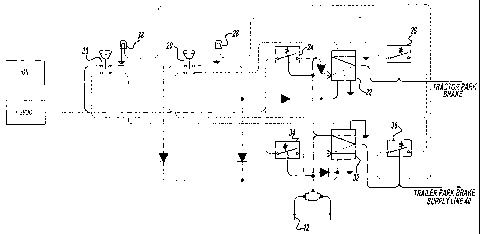
FIG. 2 is a schematic view of the present invention incorporated in a
s o truck air brake system.
DETAILED DESCRIPTION OF THE PRIOR ART
In order to understand the context of the present invention, it is desirable
to briefly review a conventional truck air brake system with reference to FIG.
1.
25 Control of the parking function is provided by a push-pull control valve 10
which is a
mechanical, pneumatic valve capable of applying line pressure in a first
position and
exhausting the line pressure that is applying the parking brakes in a second
position.
Air pressure provided by a reservoir 12 filows through the valve 10 and
through a
spring brake relay valve 16 to release (deactivate) spring brakes 18 and allow
normal
2 o movement of the vehicle. When the push-pull control valve 10 pin is
activated, the line
to spring brake 18 is vented to atmosphere and the spring brake activates the
parking
brake. Normal service braking is accomplished using a pedal mounted service
brake
valve 14 which, when activated, supplies air from both service reservoirs 12
to the
front and rear service chambers of the brake portion of the spring brake
actuator.
3


CA 02418825 2003-02-21
WO 02/24504 PCT/USO1/29142
Spring brake relay valve 16 will actuate the spring applied parking brakes if
both
service circuit reservoirs are failed.
DETAILED DESCRIPTION OF THE PREFERRED EMBODIMENT
The following description of the preferred embodiment is merely
exemplary in nature, and is no way intended to limit the invention or its
application or
uses.
Shown in FIG. 2 is a schematic of the present invention showing an
electro-pneumatic brake controller capable of controlling a parking brake and
trailer
supply tine for the trailer parking brakes. In the figure, dashed lines
represent
electrical conductors whereas solid lines designate airflow lines. Starting
with the
electrical function of the parking brake portion of the circuit, a parking
brake switch 20
of the double pole-double momentary contact throw type is provided on the
instrument
panel. The switch 20 is spring loaded to a normally center position, and can
be
15 depressed which provides a signal to a latching solenoid air valve 22,
causing the
valve to move to an open position. In the open position, air from the
reservoir 12 can
pass through the latching solenoid air valve 22 to the tractor parking brake
and release
the brake. When the parking brake switch 20 is pulled, a circuit is completed
which
moves the solenoid air valve 22 to an exhaust position. The line pressure to
the
~ o parking brake then goes to atmospheric pressure and the tractor parking
brake is
applied. Low-pressure switch 24 automatically moves the latching solenoid air
valve
22 to the exhaust position when the line pressure from the reservoir 12 goes
below a
preset limit. Additionally, a low pressure indicating switch 26 turns on a
park brake
indicator light 28 on the instrument panel of the vehicle when the line
pressure to the
4


CA 02418825 2003-02-21
WO 02/24504 PCT/USO1/29142
park brake goes below the preset limit, indicating application of the parking
brake.
Further shown in FIG. 2 is a schematic of the present invention showing
an electro-pneumatic circuit capable of controlling the trailer parking brake
supply line
for the trailer brakes. Starting with the electrical function of the trailer
parking brake
supply line portion of the circuit, a trailer supply switch 30 is provided on
the instrument
panel. The switch 30 is a double pole-double throw momentary contact switch
like
switch 20, and is spring loaded to a normally off position. Switch 30 can be
depressed
which provides a signal to a latching solenoid air valve 32, causing the valve
to move
to an open position. In the open position, air from reservoir 12 can pass
through the
s o latching solenoid air valve 32 to a trailer parking brake supply line 40
and release the
trailer brakes. When the trailer supply switch 30 is pulled, a circuit is
completed which
moves the solenoid air valve 32 to an exhaust position. The line pressure to
the trailer
parking brake supply line 40 then goes to atmospheric pressure and the trailer
brakes
are applied. A low-pressure switch 34 is provided which automatically moves
the
z5 latching solenoid air valve 32 to the exhaust position when the line
pressure from the
reservoir 12 goes below a presefi limit. Additionally a low pressure
indicating switch 36
turns on a trailer supply indicator light 38 on the instrumenfi panel of the
vehicle when
the line pressure to the trailer parking brakes goes below the preset limit,
indicating
application of the trailer parking brakes.
2 o As required by FMVSS No. 'f 21, an interlock is provided such that when
the parking brake switch 20 is retracted and the parking brakes are applied,
the trailer
supply latching solenoid air valve 32 also moves to the exhaust position,
applying the
trailer parking brakes.
The special feature of the latching solenoid air valves 22 and 32 is that
5


CA 02418825 2003-02-21
WO 02/24504 PCT/USO1/29142
they are magnetically, spring or pneumatically latched to either of the
respective open .
or exhaust positions, and can only change position upon application of the
appropriate
electrical signal to cause a change in state. Should power be lost, the
latching
solenoid air valves 22 and 32 will remain in the previous set states. Thus, a
loss of
electrical power will not cause an automatic application of the vehicle
parking brakes.
Latching solenoid air valves 22 and 32 are commercially available such as
Parker
Hannifin Skinner Model 70p0 series latching solenoid air valves. FIG. 2
further shows
a number of diodes in the electrical circuit. These devices provide circuit
isolation
required for proper system operation.
s o The foregoing discussion discloses and describes a preferred
embodiment of the invention, one skilled in the art wit( readily be recognized
from this
discussion, and from the accompanying drawings and claims, that changes and
modifications can be made to fhe invention without departing from the true
spirit and
fierce scope of the invention as defined in the following claims.
6

Representative Drawing
A single figure which represents the drawing illustrating the invention.
Administrative Status

For a clearer understanding of the status of the application/patent presented on this page, the site Disclaimer , as well as the definitions for Patent , Administrative Status , Maintenance Fee  and Payment History  should be consulted.

Administrative Status

Title Date
Forecasted Issue Date 2009-08-25
(86) PCT Filing Date 2001-09-19
(87) PCT Publication Date 2002-03-28
(85) National Entry 2003-02-21
Examination Requested 2006-06-20
(45) Issued 2009-08-25
Expired 2021-09-20

Abandonment History

Abandonment Date Reason Reinstatement Date
2003-09-19 FAILURE TO PAY APPLICATION MAINTENANCE FEE 2004-02-05

Payment History

Fee Type Anniversary Year Due Date Amount Paid Paid Date
Application Fee $300.00 2003-02-21
Reinstatement: Failure to Pay Application Maintenance Fees $200.00 2004-02-05
Maintenance Fee - Application - New Act 2 2003-09-19 $100.00 2004-02-05
Registration of a document - section 124 $100.00 2004-04-23
Maintenance Fee - Application - New Act 3 2004-09-20 $100.00 2004-08-31
Maintenance Fee - Application - New Act 4 2005-09-19 $100.00 2005-09-01
Request for Examination $800.00 2006-06-20
Maintenance Fee - Application - New Act 5 2006-09-19 $200.00 2006-09-01
Maintenance Fee - Application - New Act 6 2007-09-19 $200.00 2007-09-10
Maintenance Fee - Application - New Act 7 2008-09-19 $200.00 2008-09-03
Final Fee $300.00 2009-06-10
Maintenance Fee - Patent - New Act 8 2009-09-21 $200.00 2009-08-14
Maintenance Fee - Patent - New Act 9 2010-09-20 $200.00 2010-09-02
Maintenance Fee - Patent - New Act 10 2011-09-19 $250.00 2011-09-08
Maintenance Fee - Patent - New Act 11 2012-09-19 $250.00 2012-09-07
Maintenance Fee - Patent - New Act 12 2013-09-19 $250.00 2013-09-09
Maintenance Fee - Patent - New Act 13 2014-09-19 $250.00 2014-09-05
Maintenance Fee - Patent - New Act 14 2015-09-21 $250.00 2015-09-04
Maintenance Fee - Patent - New Act 15 2016-09-19 $450.00 2016-08-25
Maintenance Fee - Patent - New Act 16 2017-09-19 $450.00 2017-09-11
Maintenance Fee - Patent - New Act 17 2018-09-19 $450.00 2018-09-10
Maintenance Fee - Patent - New Act 18 2019-09-19 $450.00 2019-09-09
Maintenance Fee - Patent - New Act 19 2020-09-21 $450.00 2020-09-07
Owners on Record

Note: Records showing the ownership history in alphabetical order.

Current Owners on Record
BENDIX COMMERCIAL VEHICLE SYSTEMS LLC
Past Owners on Record
EBERLING, CHARLES E.
HONEYWELL COMMERCIAL VEHICLE SYSTEMS COMPANY
Past Owners that do not appear in the "Owners on Record" listing will appear in other documentation within the application.
Documents

To view selected files, please enter reCAPTCHA code :


To view images, click a link in the Document Description column. To download the documents, select one or more checkboxes in the first column and then click the "Download Selected in PDF format (Zip Archive)" or the "Download Selected as Single PDF" button.

List of published and non-published patent-specific documents on the CPD .

If you have any difficulty accessing content, you can call the Client Service Centre at 1-866-997-1936 or send them an e-mail at CIPO Client Service Centre.


Document
Description 
Date
(yyyy-mm-dd) 
Number of pages   Size of Image (KB) 
Abstract 2003-02-21 1 57
Claims 2003-02-21 4 153
Drawings 2003-02-21 2 48
Description 2003-02-21 6 258
Representative Drawing 2003-02-21 1 15
Cover Page 2003-05-02 1 40
Representative Drawing 2009-07-28 1 11
Cover Page 2009-07-28 1 42
PCT 2003-02-21 6 211
Assignment 2003-02-21 3 100
Correspondence 2003-04-23 1 24
Correspondence 2003-05-29 3 129
Correspondence 2003-08-22 1 25
Fees 2004-02-05 1 38
Assignment 2004-04-23 4 252
Prosecution-Amendment 2006-06-20 1 33
Correspondence 2004-05-26 1 14
Correspondence 2009-06-10 1 31