Note: Descriptions are shown in the official language in which they were submitted.
CA 02418840 2003-02-12
BLOW MOLDED BASKETBALL BACKBOARD FRAME
101]
BACKGROUND OF THE INVENTION
Field of the Invention
[021 The present invention generally relates to basketball backboards and, in
particular, to a basketball backboard frame that is constructed from blow-
molded plastic.
Description of Related Art
1031 As the game of basketball continues to increase in popularity, a large
number of
people have purchased basketball systems for use at their homes. Such
basketball systems
typically include a support pole, which is held in a fixed position while
playing the game of
basketball, and goal assembly that is attached to the upper portion of the
support pole. The
goal assembly, which is suspended a given distance above a playing surface,
includes a
basketball backboard and goal or hoop.
104] Conventional basketball systems designed for use at home often include
basketball backboards with a metal frame that is constructed from a number of
individual
sections that are joined together: The metal frame is typically attached to
the support pole
2
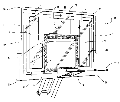
CA 02418840 2003-02-12
by a support structure that includes two or more elongated arms. The
backboard, which
often includes a rebound member or basketball backboard panel, is generally
attached to the
metal support frame by one or more screws or bolts. The assembly of the metal
frame,
however, often requires a significant amount of time and labor. In addition,
because the
metal frame is relatively heavy, a strong and sturdy support pole and
connecting arms are
required to support the basketball backboard and frame above the playing
surface.
[05] Basketball backboards for use with home basketball systems have
previously
been constructed from solid materials such as wood. Disadvantageously, wooden
basketball
backboards deteriorate over time, especially when used in outdoor environments
because the
backboards are constantly exposed to harsh weather environments such as rain
and snow.
Basketball backboards for home basketball systems have also been constructed
from
injection molded plastic. Injection molded plastic backboards, however, are
relatively.
flexible and that causes poor rebounding characteristics. That is, when the
basketball strikes
the injection molded backboard, the backboard will flex and the basketball
will not bounce
off of the backboard in a consistent manner. In order to overcome this
problem, injection
molded plastic backboards typically include strengthening ribs and other
complex structures
in an attempt to make the backboards more rigid. These strengthening ribs and
other
structures, however, increase the weight and cost of the backboard.
Additionally, known
basketball backboards may be constructed using a structural foam material with
an internal
cellular structure and a hard external shell. This type of backboard requires
a multiple step
manufacturing process, which increases the time and cost to manufacture the
backboard.
(06] One feature of home basketball systems that is becoming more popular is
the use
of transparent or clear backboards, so that the backboards resemble those used
in
3
CA 02418840 2003-02-12
professional and collegiate games.. In particular, most professional leagues
and major
colleges use tempered glass backboards to allow spectators to view the game
through the
backboard. Tempered glass backboards are generally three-eighths (3/8) to one-
half (1/2) of
an inch thick, and the tempered glass is very heavy. Thus, a large support
frame and pole
are required to support the glass backboard above the playing surface.
1071 In order to create a look similar to the tempered glass backboards used
in
professional and college games, transparent or clear backboards are now being
used in
connection with home basketball systems. For example, conventional home
basketball
systems may use a welded steel frame with a clear, planar acrylic panel
attached to the front
surface of the frame. Disadvantageously, the outer edges of the acrylic panel
are often
exposed and not supported by the metal frame. This allows the edges of the
acrylic panel to
be broken or damaged when struck by a basketball or other object. The broken
or damaged
acrylic panels are generally very difficult and expensive for the consumer to
fix or replace.
[081 Conventional basketball backboards constructed from acrylic panels may
also be
attached to the frame by double-sided adhesive tape. The double-sided adhesive
tape must
securely bond the backboard to the frame. The double-sided tape must also
allow impact
energy from the basketball striking the backboard to be transferred to the
frame, and the tape
must have sufficient flexibility to dissipate the impact energy from the
backboard to the
frame. If the attachment of the basketball backboard to the frame is too
rigid, then the
backboard can fracture. On the other hand, if the attachment of the basketball
backboard to
the frame is too loose, then backboard may dislodge or separate from the frame
and it may
fall to the playing surface. This often damages the backboard and it creates a
safety hazard
for persons playing basketball.
4
CA 02418840 2003-02-12
[09[ The process for attaching acrylic basketball backboards to the frame with
double-
sided adhesive tape is relatively time consuming and labor intensive. In
particular, in order
to attach the backboard to the frame, the frame and acrylic backboard must
first be cleaned
and/or prepared to receive the double-sided tape. The tape must also be cut or
formed into
the proper size and then the backing on one side of the tape is removed. The
tape is then
attached to the frame and the backing on the other side of the tape is
removed. The acrylic
panel is then attached to the frame, and the panel and frame must be firmly
pressed together
to ensure complete adhesion and attachment of the panel and frame. The panel
and frame
must then be carefully checked to ensure the tape is securely attached the
panel to the frame.
[010] It is known to use double-sided adhesive tape with a foam center to
attach the
backboard to the frame. One suitable type of double-sided adhesive tape, known
as "VHB"
tape, is commercially available from the Minnesota Mining and. Manufacturing
Co. (3M) of
Saint Paul, Minnesota and the Norton Company of Worchester, Massachusetts.
[011] It is also known to use an injection molded plastic frame to support a
transparent
acrylic backboard. The injection molded plastic frame includes separately
molded front and
rear sections that are connected to form the frame. In particular, the front
and rear sections
of the frame may include alignment features that allow the sections to be
attached in, the
desired manner and a slot or opening is disposed between the front and rear
sections. A
substantially planar rebound member constructed from molded plastic is
inserted into the
slot to form the basketball backboard. The injection molded frame typically
requires
structural foam or fiberglass-reinforced plastic to provide the required
strength to support
the rebounding member and provide the proper rebound performance.
CA 02418840 2003-02-12
[0121 Disadvantageously, the two-piece, injection molded plastic frame is
relatively
heavy and it requires a significant amount of labor to attach the front and
rear sections of the
frame and insert the rebound member into the slot between the sections.
Significantly, this
type of basketball backboard generally does not have a flat front surface. In
particular,
because the rebound member is located between the front and rear sections, the
outer portion
of the frame is not aligned with .the front face of the rebound member. Thus,
the backboard
has an uneven front surface and when a basketball strikes the uneven surfaces,
the basketball
will not have a true bounce and unexpected results may occur.
6
CA 02418840 2003-02-12
ti
BRIEF SUMMARY OF THE INVENTION
[013] A need therefore exists for a basketball backboard frame that eliminates
the
above-described disadvantages and problems.
[014] One aspect of the basketball backboard frame is it is desirably
constructed from
blow-molded plastic and it includes a generally hollow interior portion.
Significantly, the
lightweight basketball backboard frame can be easily transported, which
decreases shipping
costs. The lightweight basketball backboard frame can also be easily moved and
stored.
Additionally, the lightweight basketball backboard frame allows a basketball
goal system to
be easily constructed and assembled. Further, because the basketball backboard
frame is
lightweight, it does not require a large support structure to support the
backboard above the
playing surface.
[015] Another aspect of the basketball frame is one or more depressions, "tack-
offs" or
"kiss-offs," may be formed in the frame. The depressions, which extend from
one surface
towards another surface, are desirably sized and configured to increase the
strength and/or
rigidity of the frame. Preferably, the depressions extend from one surface and
contact or
engage an opposing surface, but the depressions do not have to contact or
engage the
opposing surface. The depressions are desirably formed in the back or rear
surface of the
basketball backboard frame so that the depressions are generally not visible
while playing
the game of basketball. The depressions, however, may also be formed in the
front surface
or other surfaces of the basketball backboard frame. If the depressions are
formed in the
front surface of the frame, these depressions may be covered in whole or in
part by the
backboard or rebound member. In addition, one or more depressions may be
formed in the
rear surface of the frame and one or more depressions may be formed in the
front surface of
7
CA 02418840 2003-02-12
the frame, and these opposing depressions may be generally aligned. At least a
portion of
these opposing depressions preferably contact or engage each other, but the
opposing
depressions do not touch or engage. Finally, a portion of the basketball
backboard frame
may include one or more depressions on one surface and one or more depressions
in an
opposing surface.
[016] Advantageously, the blow-molded plastic basketball backboard frame is
relatively strong because it preferably includes two or more opposing walls or
surfaces that
are separated by a given distance. The opposing walls help create a high-
strength, rigid
basketball backboard frame. Because the interior portion of the frame between
the opposing
walls is generally hollow, that creates a lightweight backboard frame.
Significantly, the
strong and sturdy basketball backboard frame can withstand repeated impacts
with a
basketball or other similar objects. Further, the strong and rigid frame
securely supports the
backboard, which allows a basketball system with good rebounding
characteristics to be
constructed.
[017] Significantly, the basketball backboard frame can be quickly and easily
constructed because it is preferably constructed using a blow-molded plastic
process.
Advantageously, the blow-molding process allows the double walls and any
suitable number
of depressions to be quickly and easily formed. As discussed above, the double
walls and
depressions allow a strong and sturdy frame to be constructed. These and other
features also
allow the basketball backboard frame to be constructed with relatively thin
plastic walls and
that reduces the amount of materials used to construct the frame. This saves
manufacturing
costs and reduces the amount of resources required to construct the frame. The
thin plastic
8
CA 02418840 2003-02-12
ti
walls also allow the frame to be cooled more quickly during the manufacturing
process, and
that saves time and further decreases costs.
[018] Yet another aspect of the basketball backboard frame is it can be
constructed in
any desired configuration, shape, size and design depending, for example, upon
the intended
use and/or configuration of the backboard. Significantly, if the basketball
backboard frame
is constructed from blow-molded plastic, it can easily be formed into any
desired size,
configuration, and color. Further, basketball backboard frames constructed
from blow-
molded plastic are durable, weather resistant and generally temperature
insensitive. The
blow-molded plastic basketball backboard frames, in contrast to conventional
metal frames,
do not corrode, rust or otherwise deteriorate over time.
[019] Another aspect of the basketball backboard frame is it preferably
includes an
outer periphery or exterior. This outer periphery, for example, may have a
generally
rectangular configuration with generally parallel disposed upper and lower
surfaces. The
outer periphery of the frame, however, may also be curved, fan-shaped or have
other desired
shapes and configurations. The outer periphery desirably encloses a generally
open center
portion. This generally open center portion further decreases the weight of
the frame.
[020] Still another aspect of the basketball backboard frame is a generally H-
shaped
support structure may be disposed within the outer periphery of the frame. The
H-shaped
support structure preferably divides the frame into four distinctive areas
with a right side
portion, left side portion, upper center portion and lower center portion.
Advantageously,
the H-shaped support structure allows the basketball backboard or rebound
member to be
securely supported.
9
CA 02418840 2003-02-12
[021] A further aspect is a basketball backboard frame with a generally Y-
shaped
support structure disposed within the outer periphery of the frame. The Y-
shaped support
structure preferably divides the frame into three distinctive areas with a
right side portion,
left side portion and a center portion. The Y-shaped support structure also
allows the
basketball backboard or rebound member to be securely supported.
[022] Another aspect of the basketball backboard frame is a generally X-shaped
support structure may be disposed within the outer periphery of the frame. The
X-shaped
support structure preferably divides the frame into at least three distinctive
areas with a right
side portion, left side portion, and a center portion. The X-shaped support
structure can also
divide the frame into four or more distinctive areas with a right side
portion, left side potion,
upper center portion and lower center portion. Advantageously, the X-shaped
support
structure also allows the basketball backboard or rebound member to be
securely supported.
[023] Yet another aspect of the basketball backboard fame is a double I-shaped
support structure may be disposed within the outer periphery of the frame. The
double I-
shaped support structure consists of two generally vertical members which
preferably divide
the frame into three distinctive areas with a right side portion, left side
portion, and a center
portion. In a preferred embodiment of the I-shaped support structure, the
right, left and
center areas are of equal area. Advantageously, the double I-shaped support
structure also
allows the basketball backboard or rebound member to be securely supported.
[024] Another aspect of the basketball backboard frame is an adhesive is
preferably
used to bond the backboard to the frame. The backboard is preferably a
generally flat,
planar structure that is constructed from acrylic. Advantageously, acrylic
basketball
backboards may be clear or generally transparent to allow light to be
transmitted through the
CA 02418840 2003-02-12
backboard. The backboard may also contain designs, graphics, or other printed
material.
The backboard is preferably attached to the frame by art elastomeric adhesive.
More
preferably, a silicon based adhesive is used to attach the backboard to the
frame, but other
types of adhesives may also be used. The backboard is preferably spaced from
the frame by
a bond gap, and the size of the bond gap may be controlled by bond gap
spacers. The bond
gap spacers may either be structural elements of the support frame or be a
separate structure
within the adhesive. Beads, for example, may be used as bond gap spacers.
[025) These and other aspects, features and advantages of the present
invention will
become more fully apparent from the following detailed description of
preferred
embodiments and appended claims.
11
CA 02418840 2003-02-12
BRIEF DESCRIPTION OF THE DRAWINGS
[026) The appended drawings contain figures of preferred embodiments to
further
clarify the above and other aspects, advantages and features of the present
invention. It will
be appreciated that these drawings depict only preferred embodiments of the
invention and
are not intended to limits its scope. The invention will be described and
explained with
additional specificity and detail through the use of the accompanying drawings
in which:
[027] Figure 1 is a perspective view of a basketball backboard frame in
accordance
with a preferred embodiment of the invention, illustrating a basketball
backboard attached to
the basketball backboard frame and a generally H-shaped support structure;
[028] Figure 2 is a front view of the basketball backboard frame and
basketball
backboard shown in Figure 1;
[0291 Figure 3 is a rear view of the basketball backboard frame and basketball
backboard shown in Figure 1;
[030] Figure 4 is a front view of a basketball backboard frame in accordance
with
another preferred embodiment of the invention, illustrating a generally Y-
shaped support
structure;
[031] Figure 5 is a front view of a basketball backboard frame in accordance
with
another preferred embodiment of the invention, illustrating a generally X-
shaped support
structure;
[032] Figure 6 is a front view of a basketball backboard frame in accordance
with
another preferred embodiment of the invention, illustrating a generally double
I-shaped
support structure;
12
CA 02418840 2003-02-12
10331 Figure 7 is a front view of a basketball backboard frame in accordance
with
another preferred embodiment of the invention, illustrating a frame with a
different exterior
configuration;
[0341 Figure 8 is a front view of a basketball backboard frame in accordance
with yet
another preferred embodiment of the invention, illustrating a. frame with a
different exterior
configuration;
[0351 Figure 9 is a front view of a basketball backboard frame in accordance
with still
another preferred embodiment of the invention;
1036] Figure 10 is an enlarged cross-sectional side view of a portion. of the
basketball
backboard frame and basketball backboard along lines 10-10 shown in Figure 3,
illustrating
a depression with a distal end contacting an opposing surface;
[037] Figure 11 is an enlarged cross-sectional side view of a portion of the
basketball
backboard frame and basketball backboard along lines 11-11 shown in Figure 3,
illustrating
a depression with a distal end disposed proximate an opposing surface;
[038] Figure 12 is an enlarged cross-sectional side view of an exemplary
portion of a
basketball backboard frame, illustrating a screw boss and an exemplary
fastener; and
1039] Figure 13 is an enlarged cross-sectional side view of an exemplary
portion of a
basketball backboard frame, illustrating another embodiment of a screw boss
and an
exemplary fastener.
13
CA 02418840 2003-02-12
DETAILED DESCRIPTION OF THE PREFERRED EMBODIMENTS
[040] The present invention is directed towards a basketball backboard frame.
The
principles of the present invention, however, are not limited to a basketball
backboard
frame. It will be understood that, in light of the present disclosure, the
basketball backboard
frame disclosed herein can be successfully used in connection with other types
of basketball
and sporting equipment.
[041] Additionally, to assist in the description of the basketball backboard
frame,
words such as top, bottom, front, rear, right and left are used to describe
the accompanying
figures. It will be appreciated, however, that the present invention can be
located in a
variety of desired positions--including various angles, sideways and even
upside down. A
detailed description of the basketball backboard frame now follows.
[0421 As seen in Figure 1, a basketball goal system 10 includes a backboard 12
and a
support frame 14. The backboard 12 has a generally smooth, planar outer
surface so that a
basketball bounces or rebounds off the backboard in a consistent manner.
The,backboard 12
is preferably constructed from plastic and, in particular, from an acrylic
sheet that has
sufficient thickness so that it will not break during an ordinary game of
basketball. The
backboard 12 is preferably constructed from an acrylic sheet because it is
lightweight, easy
to manufacture, and allows the basketball goal system 10 to be easily
assembled. In
addition, the backboard 12 is preferably constructed from acrylic or other
suitable clear,
transparent or generally translucent materials so that light can pass through
the backboard.
This creates a basketball goal system 10 that is similar in appearance and
characteristics to
those used in professional and major college games. One skilled in the art,
however, will
14
CA 02418840 2003-02-12
realize that the backboard 12 can be constructed from any suitable materials
and the
backboard can be constructed from opaque or other types of solid materials.
1043] The basketball backboard support frame 14 is preferably constructed from
a
lightweight material, such as plastic. Desirably, the support frame 14 is
constructed from
blow-molded plastic to create a strong, lightweight and durable frame. In
greater detail, the
support frame 14 is preferably constructed using a blow-molded plastic
process, and the
frame includes two opposing walls or surfaces that are separated by a given
distance in order
to create a strong and sturdy structure. In addition, the interior portion of
the blow-molded
support frame 14 is preferably generally hollow. Advantageously, this creates
a support
frame 14 that is lightweight, strong and rigid, which allows the frame to
withstanA repeated
impacts with a basketball or other similar objects.
[044] The basketball backboard support frame 14 is preferably constructed from
blow-
molded plastic because it can easily be formed into any desired size and
configuration. The
basketball backboard support frame 14 is also desirably constructed from blow-
molded
plastic because it is durable, weather resistant and generally temperature
insensitive.
Advantageously, the basketball backboard support frame 14 constructed from
blow-molded
plastic generally does not corrode, rust or otherwise deteriorate over time.
[045] The basketball backboard support frame 14 is preferably constructed from
lightweight, blow-molded plastic because weight reduction of the basketball
goal system 10
is highly desirable. For example, many home basketball systems are marketed
directly to
consumers in retail stores. Thus, the purchaser may be required to bring the
basketball
system to a register to be purchased, load the system in a vehicle, and.
assemble the system at
home. If the basketball backboard 12 and support frame 14 are heavy, then the
weight of the
CA 02418840 2003-02-12
basketball goal system 10 and the overall weight of the entire basketball
system is increased.
If the basketball goal system 10 is heavy, that may also require a heavier and
more complex
support system which further increases the overall weight of the basketball
system. A
consumer may be reluctant to purchase and assemble a basketball system that is
too heavy.
[046] Advantageously, constructing the basketball backboard support frame 14
from
lightweight, blow-molded plastic decreases shipping costs, whether shipping
the system
from the manufacturer to a retailer or consumer. In contrast, conventional
basketball
backboard frames that were constructed from pieces of metal that were welded
together
were heavy and the extra weight increased shipping costs. The blow-molded
basketball
frame 14, however, is lightweight and it allows for the overall weight of the
basketball goal
system 10 to be decreased. The lightweight backboard support frame 14 also
simplifies the
attachment of the basketball goal system 10 to the support pole or other
support structure
(not shown) because the lighter weight goal system is easier to manipulate and
control
during the assembly process. Advantageously, because the basketball backboard
support
frame 14 is lightweight, the pole and/or other support structure does not have
to support a
heavy basketball goal system 10. This allows the pole and/or other support
structure to be
constructed from lighter weight materials.
[047] As known to those skilled in the art, the height of the basketball goal
system 10
may be adjustable and a counterbalance or counterweight may be used to support
the goal
system at the desired height. Significantly, because the basketball backboard
support frame
14 may be constructed from lightweight blow-molded plastic, a smaller
counterbalance or
counterweight may be used to support the basketball goal system 10.
Additionally, as
known to those skilled in the art, the counterbalance may consist of a spring
or piston that
16
CA 02418840 2003-02-12
may be attached to various portions of the basketball goal system 10. The
lightweight
support frame 14 allows a smaller spring or piston to be used. The smaller
spring,
counterbalance or counter weight may further decrease the overall weight of
the basketball
system.
[048] The basketball backboard support frame 14 is preferably constructed from
blow-
molded plastic because it allows multiple features to be formed in the frame.
For example,
various support and mounting structures may be created in the frame 14 during
the blow-
molding process. In particular, one or more holes used to mount a basketball
goal 8 to the
support frame 14 may be created during the blow-molding process. Thus, a
drilling step can
be eliminated from the manufacturing process. This and other features formed
during the
blow-molding process can save time and manufacturing costs. In addition, the
features are
preferably integrally formed in the frame 14 and simultaneously created during
the blow-
molding process. Because these features may be simultaneously formed during
the blow-
molding process, this may save costs because the overall manufacturing cost of
a product
generally increases with each additional manufacturing step.
[049] The basketball backboard support frame 14 is also preferably constructed
as a
unitary, one-piece structure. Advantageously, this further decreases
manufacturing costs
and time because one or more components do not have to be assembled or
fastened together.
In addition, the one-piece structure allows a strong and sturdy support frame
14 to be
manufactured. It will be appreciated that the support frame 14, however, may
be
constructed by one or more components that are fastened together by any
suitable means.
[050] As shown in the accompanying figures, the basketball backboard support
frame
14 preferably has a generally rectangular outer periphery or exterior. For
example, as shown
17
CA 02418840 2003-02-12
in Figures 1 to 6, the support frame 14 includes a top surface 16 that is
generally parallel to a
bottom surface 18, and a left side 20 that is generally parallel to a right
side 22 of the frame.
It will be appreciated, however, that the outer edges of the frame 14 do not
have to be
generally parallel and the frame does not require a generally rectangular
configuration. For
example, the outer edges of the frame 14 can be curved, rounded, arched, fan-
shaped, or
have any suitable design and configuration depending, for example, upon the
intended use of
the frame.
[051] The frame 14 also includes an upper left corner 24, an upper right
corner 26, a
lower left corner 28 and a lower right comer 30. As shown in Figures 1 to 6,
the comers 24,
26, 28 and 30 are generally formed at about a 90 angle and the corners have a
relatively
small curved outer portion. The corners 24, 26, 28 and 30 shown in Figures 7
and 8,
however, include a larger curved outer portion. The corners 24, 26, 28 and 30
shown in
Figure 9, in contrast, have a different curved outer portion. Desirably, the
upper comers 24,
26 and lower corners 28, 30 have a similar size and appearance, but it will be
appreciated
that the corners may have varied or different sizes and configurations. It
will also be
appreciated that the comers 24, 26, 28 and 30 may have any suitable size,
radius of
curvature and/or configuration depending, for example, upon the intended use
of the frame
14. Of course, if the frame 14 has a curved, rounded, arched, fan-shaped or
other similar
configuration, then the frame may not include one or more corners 24, 26, 28
or 30.
[052] As best seen in Figures 7-9, the basketball backboard support frame 14
preferably also includes one or more bonding surfaces 32 that are used when
the backboard
12 is attached to the frame. The bonding surfaces 32 are located on the front
face of the
frame 14 and the bonding surfaces may cover all or a portion of the front face
of the frame.
18
CA 02418840 2003-02-12
The bonding surfaces 32 are preferably generally planar surfaces but the
bonding surfaces
may have any suitable configuration depending, for example, upon the size and
configuration of the backboard 12. The bonding surfaces 32 are preferably
formed during
the blow molding process and these surfaces allow the backboard 12 to be
securely attached
to the support frame 14. As shown in the accompanying figures, the support
frame 14 may
include a gap, step or other alignment feature 34 to assist in aligning the
backboard 12
relative to the frame. Desirably, the gap 34 has a thickness generally
equivalent or the same
as the thickness of the backboard 12. Thus, when the backboard 12 is attached
to the frame
14, the front face of the frame and the backboard are aligned to create a
generally planar
surface. The backboard 12 desirably includes one or more bonding surfaces that
are sized
and configured to allow the backboard to be attached to the frame 14.
[053] As shown in Figures 1-3, the basketball backboard frame 14 includes a
generally
"H"-shaped support structure 40 disposed between the outer edges or periphery
of the frame.
The generally "H"-shaped support structure 40 is preferably centrally disposed
between the
left side 20 and right side 22 of the frame 14, and the support structure 40
includes a first
lateral support member 42, a second lateral support member 44 and a horizontal
support
member 46. One skilled in the art will recognize that the support structure 40
does not
require a generally "H"-shaped configuration and the support structure can
have any suitable
size and configuration depending, for example, upon the intended use of the
frame 14.
[054] The "H"-shaped support structure 40 desirably divides the frame 14 into
four
distinctive openings or sections 50, 52, 54 and 56 disposed between the
support structure
and the periphery of the frame 14. Advantageously, the "H"-shaped support
structure 40
and outer edges of the frame 14 securely support the backboard 12 such that a
basketball
19
CA 02418840 2003-02-12
rebounding from the backboard will deflect the backboard a minimal amount.
This creates a
backboard 12 with very good rebounding characteristics. Desirably, the
rebounding
characteristics of the basketball goal system 10 are generally similar to the
rebounding
characteristics of a one-piece, generally solid backboard. The large openings
50, 52, 54, and
56, however, allow a lightweight basketball goal system 10 to be created.
[0551 As shown in Figure 4, the basketball backboard frame 14 may also include
a
generally "Y"-shaped support structure 140 disposed between the outer edges or
periphery
of the frame. The generally "Y"-shaped support structure 140 is preferably
centrally
disposed between the left side 20 and right side 22 of the frame 14, and the
support structure
140 includes a first lateral support member 142, a second support member 144,
and a third
support member 146.
[0561 The "Y"-shaped support structure 140 desirably divides the frame 14 into
three
distinctive openings or sections 150, 152, and 154 disposed between the
support structure
and the periphery of the frame 14. Advantageously, the "Y"-shaped support
structure 140
and outer edges of the frame 14 securely support the backboard 12 such that a
basketball
rebounding from the backboard will deflect the backboard a minimal amount.
This creates a
backboard 12 with very good rebounding characteristics. Desirably, the
rebounding
characteristics of the basketball goal system 10 are generally similar to the
rebounding
characteristics of a one-piece, generally solid backboard. The large openings
150, 152, and
154, however, allow a lightweight basketball goal system 10 to be created.
[0571 As shown in Figure 5, the basketball backboard frame 14 may also include
a
generally "X"-shaped support structure 240 disposed between the outer edges or
periphery
of the frame. The generally "X"-shaped support structure 240 is preferably
centrally
CA 02418840 2003-02-12
disposed between the left side 20 and right side 22 of the frame 14, and the
support structure
240 includes a first support member 242 and a second support member 244.
[058] The "X"-shaped support structure 240 desirably divides the frame 14 into
three
distinctive openings or sections 250, 252, and 254 disposed between the
support structure
and the periphery of the frame 14. One skilled in the art will appreciate that
the "X"-shaped
support structure 240 may also divide the frame 14 into four or more
distinctive openings or
sections disposed between the support structure and the periphery of the frame
14.
Advantageously, the "X"-shaped support structure 240 and outer edges of the
frame 14
securely support the backboard 12 such that a basketball rebounding from the
backboard
will deflect the backboard a minimal amount. This creates a backboard 12 with
very good
rebounding characteristics. Desirably, the rebounding characteristics of the
basketball goal
system 10 are generally similar to the rebounding characteristics of a one-
piece, generally
solid backboard. The large openings 250, 252, and 254, however, allow a
lightweight
basketball goal system 10 to be created.
[059] As shown in Figure 6, the basketball backboard frame 14 may also include
a
generally double "I"-shaped support structure 340 disposed between the outer
edges or
periphery of the frame. The generally double "I"-shaped support structure 340
is preferably
centrally disposed between the left side 20 and right side 22 of the frame 14,
and the support
structure includes a first support member 342 and a second support member 344.
The
support members 342, 344 are preferably generally parallel aligned and
perpendicular to the
bottom surface 18 of the frame 14, but the support members can have any
desirable
configuration and/or alignment.
21
CA 02418840 2003-02-12
[0601 The double "I"-shaped support structure 340 desirably divides the frame
14 into
three distinctive openings or sections 350, 352, and 354 disposed between the
support
structure and the periphery of the frame 14. These three openings may have
generally the
same size, or they may have different sizes, depending on the placement of the
lateral
support members 342, 344. Advantageously, the double "I"-shaped support
structure 340
and outer edges of the frame 14 securely support the backboard 12 such that a
basketball
rebounding from the backboard will deflect the backboard a minimal amount.
This creates a
backboard 12 with very good rebounding characteristics. Desirably, the
rebounding
characteristics of the basketball goal system 10 are generally similar to the
rebounding
characteristics of a one-piece, generally solid backboard. The large openings
350., 352, and
354, however, allow a lightweight basketball goal system 10 to be created. Of
course, one
skilled in the art will appreciate that the support structure 340 could
include only a single
support member or more than two support members.
[061] The "H", "Y", "X" and double "I"-shaped support structures 40, 140, 240,
and
340, respectively, desirably create a high-quality, professional appearance
for the basketball
goal system 10. Basketball systems that are used in professional, major
colleges and other
such venues typically include backboards that are constructed from tempered
glass. The
tempered glass allows the game to be viewed through the backboard with minimal
obstructions. The tempered glass, however, has a relatively large thickness to
provide the
strength required for the basketball system. These backboards are generally
not practical for
home or portable basketball systems because the tempered glass is very heavy,
expensive,
and can be easily scratched or otherwise damaged.
22
CA 02418840 2003-02-12
[062] Advantageously, the support frame 14 and the variously shaped support
structures provide a basketball goal system 10 that is similar to a
professional backboard,
and is lightweight and low cost. In particular, the support frame 14 and
support structures
40, 140, 240, or 340 allow the backboard 12 to be constructed from a thin
acrylic sheet. In
addition, the variously shaped support structures 40, 140, 240, and 340 may be
sized and
configured such that a basketball target 58 covers or hides a portion of the
support structure.
For example, as seen in Figures 1 and 4, the basketball target 58 has a
generally rectangular
configuration and it is generally positioned above the basketball goal. As
known to those
skilled in the art, the basketball target 58 is used to provide a reference
for shooting and
rebounding a basketball from the backboard 12. Because the target 58 is
present on most
backboards 12, it can be used to hide portions of the support structures 40,
140, 240, or 340
from view. For example, the target 58 covers at least a portion of the first
and second lateral
support members 42, 44, and the horizontal support member 46 in the generally
"H"-shaped
support structure. This creates the appearance that the backboard 12 is only
supported by
the frame 12 and only the upper portions of the first and second lateral
support members 42
and 44 are visible. Thus, the basketball goal system 10 has the appearance of
a transparent
professional backboard, however, the basketball goal system is substantially
lighter than a
professional system. It will be appreciated, however, that the support
structures 40, 140,
240, 340, and the target 58 can have any suitable size and configuration
depending upon the
intended use of the basketball goal system 10. For example, upper portions of
the support
members 42, 44, 142, 144, 242, 244, 342, 344 can be curved, angled or have
other desired
shapes for aesthetic or functional purposes.
23
CA 02418840 2003-02-12
[063] The frame 14 may also employ various other features such as the
depressions 62
or "tack-offs" shown in Figures 3 and 6-9. The depressions 62, which extend
from one
surface towards the other surface, are desirably sized and configured to
increase the strength
and/or rigidity of the frame 14. Preferably, the depressions 62 extend from
one surface and
contact or engage an opposing surface, but the depressions do not have to
contact or engage
the opposing surface. The depressions 62 are desirably formed in the back or
rear surface of
the basketball backboard frame 14 so that the depressions are generally not
visible while
playing the game of basketball. The depressions 62, however, may also be
formed in the
front surface of the basketball backboard frame 14. These depressions 62 may
be covered in
whole or in part by the backboard 12 and/or target 58. In addition, one or
more depressions
62 may be formed in the rear surface of the frame 14 and one or more
depressions may be
formed in the front surface of the frame, and these opposing depressions are
preferably
generally aligned. Desirably, at least a portion of these opposing depressions
62 contact or
engage each other, but the opposing depressions do not have to touch or
engage. One
skilled in the art will appreciate that the number, size and location of the
depressions 62 may
depend upon factors such as the desired strength of the basketball goal system
10. Further, a
portion of the basketball backboard frame 12 may include one or more
depressions 62 on
one surface and one or more depressions in an opposing surface. For example,
the front
surface of the frame 14 may include one or more depressions that are generally
hidden by
the target 58 and the rear surface of the frame 14 may also include one or
more depressions
62 depending upon the desired characteristics of the basketball goal system
10.
[064] As seen in Figures 10 and 11, the depressions 62 preferably have
generally
tapered walls 66 and the end 68 of the depression may contact or engage the
inner surface of
24
CA 02418840 2003-02-12
the opposing wall. As discussed above, the end 68 of the depression 62 does
not have to
contact or engage the opposing surface as shown in Figure 11. As shown in the
accompanying figures, the depressions 62 preferably have a generally
trapezoidal
configuration. Advantageously, the trapezoidal configuration provides
desirable bearing and
torsional characteristics for the basketball goal system 10. For example, the
trapezoidal
shape appears to prevent the support frame 14 from bending or yielding when a
basketball
rebounds from the backboard 12. Thus, the basketball goal system 10 tends to
have
rebounding characteristics that are similar to larger and heavier backboards.
[0651 As shown in Figures 12 and 13, the support frame 14 may incorporate one
or
more screw bosses 70 to allow a fastener 72 to be connected to the frame. The
fastener 72,
for example may be used to attach the frame to a support structure. The screw
boss 70 is
located in one surface 74 and it extends towards a second surface 76. The
screw boss 70
includes a wall 78 and a distal end 80. As shown in Figure 12, the distal end
80 of the screw
boss 70 contacts the opposing surface 76. However, as seen in Figure 13, the
distal end 80
of the screw boss 70 does not have to contact the opposing surface 76.
[066] The screw boss 70 advantageously allows a fastener 72 to be attached to
the
support frame 14. It will be appreciated that the dimensions and size of the
boss 70 will
vary depending upon the application, the size of the fastener 72, and the
dimensions of the
frame 14.
[067] Desirably, in order to provide a secure attachment for the fastener 72,
a least two
threads of the fastener should engage the inner surface of the wall 78 of the
boss 70. The
thickness of the wall 78 should be of sufficient thickness to allow engagement
of the threads
of the fastener 72 without the threads piercing the wall. It will be
appreciated that the
CA 02418840 2009-10-08
thickness and the depth of the screw boss 70 will be a function of the
position of the boss 70
in the frame 14 as well as a function of the load applied to fastener 72.
[068] The screw boss 70 is desirably located in a stretch region of the frame
14
which allows the screw boss to be formed without piercing the frame or
creating a portion
of the frame in which the plastic is too thin. Additionally, the screw boss 70
may be created
with an open or closed distal end 80. These and other features of the screw
boss 70 are
described in detail in assignee's United States Patent Publication No. 2002-
0152934 Al
entitled Screw Bosses for Blow-Molded Structures, which was filed on December
5, 2001.
[069] As best seen in Figures 10 and 11, the backboard 12 is preferably bonded
to
the support frame 14 by an elastomeric adhesive 90. As discussed above, the
backboard 12
desirably includes a bonding surface 36, and the support frame 14 includes a
bonding surface
32. The elastomeric adhesive 90 is sandwiched between the two bonding surfaces
32 and 36
and the adhesive securely attaches the acrylic backboard 12 to the frame 14.
[070] Applicant determined that after testing a large number of various
elastomeric
adhesives from different suppliers, silicone adhesive was preferred because it
provides a
bond of sufficient strength and flexibility, comparable to that obtained with
conventional
foam filled, two-sided tape. It was also preferred because of its low cost and
availability.
Other adhesives, such as urethane, polyurethane, hot melt adhesives,
methylmethacrylate, and
cyanoacrylate adhesives did not perform as well as silicone in providing the
desired balance
between bond strength and flexibility and/or were more expensive.
[071] Applicant's testing indicated that silicone adhesive is preferred to
attach the
backboard 12 to the frame 14. A suitable type of silicone adhesive can be
obtained from the
26
CA 02418840 2003-02-12
General Electric Company (Part No. D1-SEA 210) or from the Dow Coming Company
(Part
No. Q3-6093). These commercially available silicone adhesive includes
dimethylpolysiloxane as a primary ingredient, with N-propylsilicate,
aminopropyltriethoxysilane, 1,3,5-tris(trimethoxysilyipropylisocyanurate) as
minor
ingredients. One skilled in the art will appreciate that other silicone
adhesives, elastomeric
adhesives, and other types of adhesives may be used to attach the backboard 12
to the
support frame 14.
[072] As shown in Figures 10 and 11, the silicone adhesive desirably has a
bond gap
"A" in the range from about 2.0 to 2.5 mm (0.08 to 0.1 inch). Significantly,
if the bond gap
"A" is too small, there may not be sufficient flexibility in the bond to
dissipate the impact
energy from the basketball striking the backboard 12. Additionally, if the
bond gap "A"
between the backboard and frame is too rigid, then the backboard may fracture.
On the
other hand, if the bond gap is too great, then the bond may not be strong
enough to securely
support the backboard 12.
[073] The adhesive bond gap "A" may be formed by bond gap spacers 92 located
between the frame bonding surface 32 and the backboard bonding surface 36.
Suitable gap
spacers 92 can be any rigid structure having the desired thickness that can
maintain the
desired bond gap "A" between the frame and backboard bonding surfaces 32, 36.
The bond
gap spacers 92 preferably have a size or diameter in the range from about 2.0
to 2.5 mm
(0.08 to 0.1 inch), but the size of the bond gap spacers may depend upon the
intended size of
the bond gap "A". In the embodiment illustrated in Figures 10 and 11, the bond
gap spacers
92 may be dimples or spacing structures molded into the bonding surface 32 of
the support
frame 14. Alternatively the bond gap spacers 92 may include separate
structures suspended
27
CA 02418840 2003-02-12
in the adhesive. For example, spherical beads, and more preferably glass
microspheres, may
be another type of bond gap spacer 92. Other bond gap spacers which have been
used
successfully include weed trimmer line and plastic beads. Alternatively, bond
gap spacers
92 do not have to be used.
[074] One problem with conventional single stage silicone adhesive is its long
cure
time, typically about 24 hours or more. If the cure time is too great, then an
undue amount
of manufacturing space is required to store the backboard assemblies while
they cure.
Applicant's testing showed that using a catalyzed silicone adhesive
significantly decreased
the cure time. The catalyzed silicone adhesive preferably used to attach the
backboard 12 to
the frame 14 contains two parts: (1) the adhesive itself and (2) a separate
catalyst which is
mixed with the adhesive to initiate curing. The ratio of catalyst to adhesive
is preferably
combined to provide a set time in the range from 5 minutes to 1 hour, and more
preferably a
set time in the range from about 7 to 15 minutes. The set time is the time at
which the
adhesive sets sufficiently to enable the backboard assembly to be moved and
handled.
[075] The bonding of the basketball backboard 12 to the support frame 14 by an
adhesive can be partially or fully completed by an automated process. For
example, a
suitable robotic device can be used to attach the backboard 12 to the frame
14, thereby
substantially reducing the assembly time and manual labor previously required
to prepare
backboard goal assemblies.
[076] In greater detail, the backboard 12 is attached to the frame 14 by
preparing
bonding surfaces 32, 36 to receive the elastomeric adhesive 90. For the frame
bonding
surface 32, this may be performed by roughening the surface. For instance, the
surface 32
can be roughened by rubbing a scouring pad, of the type commonly found in
kitchens, over
28
CA 02418840 2003-02-12
the surface. For the backboard bonding surface 36, it may be chemically
treated to break the
surface tension. Although the treatment will vary depending on the adhesive
used, it
typically will include a chemical mixture of acetone and the adhesive itself.
The appropriate
preparation of the backboard bonding surface 36 is usually provided by the
supplier of the
elastomeric adhesive 90.
[0771 It has been found that when the backboard bonding surface 36 contains a
printed
image, the printing itself provides an adequate surface preparation for the
elastomeric
adhesive 90 such that a separate backboard surface preparation step is not
necessary. The
backboard surface preparation step, however, may be performed if desired.
[078] Significantly, the elastomeric adhesive 90 can be applied to either or
both the
backboard or frame bonding surfaces 32, 36. For example, if the adhesive 90 is
applied to
the bonding surface of the backboard 36, then the support frame 12 is placed
against the
backboard 12 such that the bonding surface of the frame 32 contacts the
adhesive.
Alternatively, if the adhesive 90 is applied to the bonding surface of the
frame 32, then the
backboard 12 is placed against the frame 14 such that the bonding surface of
the backboard
36 contacts the adhesive.
[079] In either case, a predetermined bond gap "A" is maintained between the
backboard bonding surface 36 and the frame bonding surface 32. As discussed
above, the
bond gap "A" may be important to achieving a suitable balance between adhesion
and
flexibility. Additionally, as shown in Figure 3 a bond width "B" may be used
when the
adhesive 90 is applied to the frame 14 or backboard 12. A desirable bond width
"B" may be
in the range from about 1 cm to 2 cm, but the bond widths may vary depending
upon various
factors such as the type of adhesive 90 or intended use of the basketball goal
system 10. In
29
CA 02418840 2009-10-08
some applications, for example, the bond width "B" may be equal to the width
of the frame
14. Other applications may have intermittent adhesive placement, for example,
with both
wide and narrow distributions. Yet other embodiments may only use a thin line
of adhesive
at selected locations on the frame 14.
[080] Although this invention has been described in terms of certain preferred
embodiments, other embodiments apparent to those of ordinary skill in the art
are also within
the scope of this invention. Accordingly, the scope of the invention is
intended to be defined
only by the claims which follow.