Note: Descriptions are shown in the official language in which they were submitted.
CA 02420158 2003-02-20
' 4
1 /36
s Polymer Electrolyte Membrane Fuel Cell System Comprising Cooling
Medium Distribution and Collection Spaces and with Cooling by Fluid
Media
1o The present invention relates to a fuel cell system comprising a plurality
of individual polymer electrolyte membrane fuel cells arranged one
above the other in the form of a stack, said fuel cell system being
suitable for cooling using fluid media that are not, weakly or highly
electrically conductive. The invention concerns furthermore a method of
~s cooling such a fuel cell system using fluid media that are not, weakly or
highly electrically conductive. The fuel cells may be operated with fuel
gas and oxidant at low pressure or higher pressure, the fuel gas used
being preferably hydrogen or a methanol-water mixture in liquid or
gaseous form, and air or oxygen being used as oxidant.
Polymer electrolyte membrane fuel cells contain an anode, a cathode
and an ion exchange membrane disposed therebetween. A plurality of
individual fuel cells constitutes a fuel cell stack, the individual fuel cells
being separated by bipolar plates acting as current collectors. Instead of
the bipolar plates, it is also possible to use an anode-side pole plate and
a cathode-side pole plate each. For generating electricity, a fuel gas, e.g.
hydrogen, is introduced into the anode region via gas distribution
channels, and an oxidant, e.g. air or oxygen, is introduced into the
cathode region via gas distribution channels. The introduction of the
ao reactants may take place both under excess pressure (approx. 2 x 10⁵ to
4 x 10⁵ Pa) and under approximately atmospheric pressure (approx. 1.1 x
data/so52/8/53J53387/030205-t~l-applLsdwJ 2003-02-10 14:58
CA 02420158 2003-02-20
2/36
105 to 1.5 x 10⁵ Pa abs). In the regions in contact with the polymer
electrolyte membrane, the anode and cathode contain a catalyst layer
each. In the anode catalyst layer, the fuel is oxidized, forming cations and
35 free electrons, and in the cathode catalyst layer, the oxidant is reduced
by absorption of electrons. The cations migrate through the ion
exchange membrane to the cathode and react with the reduced oxidant,
creating water when hydrogen is used as fuel gas and oxygen is used as
oxidant. In the reaction of fuel gas and oxidant, there are set free large
ao amounts of heat that have to be dissipated by cooling. Cooling may be
effected both by gaseous media, e.g. air, and by fluid media.
In conventional fuel cell stacks using liquid cooling, cooling is effected by
cooling channels in the bipolar plates that are fed from central distri-
as bution and collection lines. As there are typically between 20 and 50 up
to several hundred individual fuel cells connected in series, the cooling
medium in the central supply and discharge channels must be passed
through the fuel cell stack along the direction of flow or counter thereto.
To prevent the different electrical potentials of the series-connected
5o individual fuel cells from becoming electrically interconnected by the
cooling medium, thereby causing short-circuits between the cells or
material decompositions, deionized water is used as cooling liquid.
However, deionized water has a high absorption capacity for soluble ions
of any kind, and thus it has to be continuously replaced or cleaned when
55 It is used in fuel cell systems, e.g. by ion exchanger systems. Such
cleaning is often required as the cooling media usually are passed
through heat exchanger systems where they are enriched with foreign
ions. Such foreign ions do not only undesirably increase the electric
conductivity of the cooling medium, but many of the foreign ions (Cu2+,
so Ni2+) in addition damage the solid polymer electrolyte membrane in case
there is direct contact between cooling medium and membrane.
data/so5218/53J53387/030205-trl-appli.sdw] 2003-02-10 14:58
r
CA 02420158 2003-02-20
3/36
The choice of suitable cooling media for polymer electrolyte membrane
fuel cell systems with conventional cooling thus is severely restricted.
ss There can be no cooling media used which, in direct contact with the
membrane, catalyst layer, gas diffusion layer or bipolar plate, could
cause damage thereto, as is the case e.g. with oils, cooling water
enriched with foreign ions from heat exchanger installations, cooling
water with anti-freeze agent or alcohols.
~o
These restrictions with respect to the cooling media suited for use
necessitate restrictions in the possibilities of use of the fuel cell systems.
For example, if a fuel cell system using deionized water as cooling
medium is deactivated in very cold surroundings, the cooling medium
may have frozen until reactivation thereof, causing irreversible damage
to the fuel cell system.
Another disadvantage in conventional fuel cell systems are passageways
for cooling medium through the fuel cell stack. These are complex. in
so terms of manufacture, necessitate careful sealing and, in addition
thereto, consume valuable active area.
Moreover, when the cooling medium is passed through the . stack
through central supply and discharge channels, the distribution of the
as cooling medium to the cooling channels of a bipolar plate often is not
sufficiently uniform, resulting in portions cooled to higher and lower
extents, which is not desirable. Conversely, it is hardly possible to cool
fuel cells in the central region of a stack, which as a rule is several Kelvin
hotter, to a higher extent than individual fuel cells in the peripheral
so region of the stack.
(/data/so52/8/53/53387/030205-tri-appli.sdwj 2003-02-10 14:58
A
CA 02420158 2003-02-20
4/36
It is therefore an object of the invention to overcome the disadvantages
of the prior art and to make available a constructionally simple fuel cell
system.
Another object of the invention consists in making available a fuel cell
system permitting an optimum distribution of cooling medium in accor-
dance with the degree of cooling required.
goo In particular, it is an object of the invention to make available a fuel
cell
system that is not restricted to using electrically non-conducting cooling
media, but may also be cooled using fluid media that are weakly or
strongly electrically conductive.
1o5 In addition thereto, it is an object of the invention to make available a
fuel
cell system that may be cooled with cooling media that may damage any
components of the individual fuel cells upon contact with the same.
The object is met by the fuel cell system comprising a plurality of
»o individual polymer electrolyte membrane fuel cells arranged one on top
of the other in the form of a stack, wherein
- between adjacent individual fuel cells of the stack, there is provided
one intermediate space each for receiving a cooling medium,
- on at least one lateral face of the stack, there is arranged at least one
~~5 cooling medium distribution space having at least one cooling
medium inlet opening,
on at least one lateral face of the stack, there is arranged at least one
cooling medium collection space having at least one cooling
medium outlet opening,
X20 - on the lateral faces of the stack having neither a cooling medium
distribution space nor a cooling medium collection space arranged
thereon, there is provided a sealing agent each between adjacent
Udata/so52/8/53/53387/030205-trl-appli.sdw) 2003-02-t0 14:58
CA 02420158 2003-02-20
5/36
individual fuel cells on the outer peripheral portions thereof, so that
the at least one cooling medium distribution space, the intermediate
~2s spaces between adjacent individual fuel cells and the at least one
cooling medium collection space constitute a space allowing the
flow of cooling medium therethrough.
Moreover, the object is met by the fuel cell system comprising a plurality
~so of individual polymer electrolyte membrane fuel cells arranged one on
top of the other in the form of a stack, wherein
- adjacent individual fuel cells are confined by bipolar plates having
passages for receiving a cooling medium,
- on at least one lateral face of the stack, there is arranged at least one
iss cooling medium distribution space having at least one cooling
medium inlet opening,
- on at least one lateral face of the stack, there is arranged at least one
cooling medium collection space having at least one cooling
medium outlet opening, and
1ao - the at least one cooling medium distribution space, the passages in
the bipolar plates and the at least one cooling medium collection
space constitute a space allowing the flow of cooling medium
therethrough.
ias In addition, the object is met by the method of cooling a fuel cell system
comprising a plurality of individual polymer electrolyte membrane fuel
cells arranged one on top of the other in the form of a stack, wherein a
space is provided allowing the flow of cooling medium therethrough,
said space having
~so - intermediate spaces between adjacent individual fuel cells or
passages in bipolar plates of adjacent individual fuel cells and
- at least one cooling medium distribution space arranged on a lateral
face of the stack, and
~datNso52/8153153387/030205-trl-appli.sdwJ 2003-02-10 14:58
CA 02420158 2003-02-20
6/36
- at least one cooling medium collection space arranged on a lateral
155 face of the stack, and wherein
a fluid cooling medium is flown through said space allowing the flow of
cooling medium therethrough.
The invention will be elucidated in more detail in the following by way of
~so preferred embodiments.
An individual fuel cell is composed at least of the components
membrane electrode unit, consisting of membrane, a cathode-side and
an anode-side catalyst and gas diffusion layers, and of an anode-side
ass and a cathode-side pole plate and the sealing system. Instead of the
anode-side and cathode-side pole plates of adjacent cells, it is also
possible to provide a bipolar plate. The pole plates and the bipolar plates
often have gas distribution structures incorporated therein or deposited
thereon. Each individual fuel cell also requires supply and discharge
»o means for fuel gas and oxidant. The individual fuel cells as a rule are~of
rectangular shape, but may be of any other different shape desired. The
invention will be described in the following in exemplary, non-limiting
fashion with reference to rectangular fuel cells.
1~5 For cooling the fuel cell system according to the invention, the cooling
medium is introduced into the fuel cell stack on one side thereof, flows
through the stack, i.e. flows through the intermediate spaces between
the fuel cells or through the passages in the bipolar plates, and leaves
the stack on the same side or a different side. The cooling medium is
iao preferably circulated in a loop or circuit.
Entry of the cooling medium into the stack is effected from a cooling
medium distribution space arranged on a lateral face of the stack.
(/data/so52/8153/53387/030205-trl-applLsdw] 2003-02-10 14:58
CA 02420158 2003-02-20
7/36
~a5 Upon flowing through the stack, the cooling medium is collected in a
cooling medium collection space and discharged from the fuel cell
system.
There are numerous variations possible as regards shape, number and
~so arrangement of the cooling medium distribution spaces and collection
spaces. For example, a distribution space may extend over an entire
lateral face of the fuel cell stack while another lateral face of the stack,
preferably the opposite lateral face in case of rectangular fuel cells, has a
cooling medium collection space arranged thereon that also extends
1s5 over the entire lateral face of the stack. With this embodiment, the
cooling medium flows through the stack in hydraulic parallel connection.
In case the cooling medium distribution space and the cooling medium
collection space are not provided on opposite lateral faces of the stack, it
is expedient, by introduction of suitable structures in the intermediate
zoo spaces between the cells, to provide for guided flow of the cooling
medium from its entry into the stack to its discharge from the stack and,
respectively, to design the cooling medium passages in the bipolar
plates such that they lead from the cooling medium distribution space to
the cooling medium collection space.
205
Cooling medium distribution space and collection space may be of
identical or different configuration. The distribution space has a cooling
medium inlet opening through which the cooling medium enters the
distribution space, and the collection space has a cooling medium outlet
zoo opening through which the cooling medium leaves the collection space.
In particular with high fuel cell stacks or individual fuel cells of large
area,
it may be advantageous to provide for a distributing structure in the
distribution space for improved flow guidance of the cooling medium. As
an alternative or in addition, there may also be provided several cooling
z~5 medium inlet openings in the distribution space, which also enhance a
[/data/so5218/53153387/030205-trl-appli.sdwJ 2003-02-10 14:58
CA 02420158 2003-02-20
8/36
more uniform distribution of the cooling medium introduced. The
collection space also may have several openings, i.e. outlet openings,
and contain a cooling medium distributing structure. If desired, the
direction of flow of the cooling medium may then be reversed without
22o any problem.
The cooling medium distribution space (the same applying analogously
to the collection space) may also be subdivided by partitions into two or
more segments or be composed of partial spaces that are each closed.
225 Each segment or each partial space has at least one cooling medium
inlet opening.
It is thus possible, for example, to provide three adjacent cooling
medium distribution spaces arranged on top of each other in stacking
23o direction on a lateral face of the stack, with more or colder cooling
medium being flown into the middle cooling medium distribution space
than into the other two cooling medium distribution spaces. This results
in stronger cooling of the individual fuel cells in the central region of the
stack, which in case of uniform cooling of the stack would be at a higher
235 temperature than the cells in the peripheral portion of the stack. The
same effect is achieved when cooling medium of equal temperature and
equal amount is flown into the cooling medium distribution spaces,
whereas the central cooling medium distribution space supplies cooling
medium to fewer individual fuel cells than the other two distribution
2ao spaces, so that in the central region of the stack there is a higher flow
speed, thus achieving a better cooling effect in the center.
According to a further modification of the fuel cell system according to
the invention, cooling medium distribution spaces and/or cooling
2a5 medium collection spaces may be arranged on several lateral faces of
the stack. This is advantageous in particular in case of specific cell
//datNso52/8/53/53387/030205-trl-sppli.sdw) 2003-02-10 14:58
CA 02420158 2003-02-20
9/36
shapes, for example octagonal fuel cells, for ensuring uniform cooling
medium flow.
2so Fuel cell systems in which the cooling medium flows through interme-
diate spaces between the pole plates confining adjacent individual fuel
cells, must be sealed by a suitable sealing means at those locations
where no cooling medium distribution space and no cooling medium
collection space is provided, so that the cooling medium cannot leak out
255 from the intermediate spaces. Suitable as sealing agent is any material
that is resistant to the cooling medium and withstands the fuel cell
working temperatures. For example, the intermediate spaces between
the individual fuel cells may be sealed on their outer peripheral portions
by means of silicone strips so that, seen from outside, a stacking
2so sequence of individual fuel cell -sealing means - individual fuel cell -
sealing means etc. is formed. The sealing means may be adhesively
attached to the pole plates of the adjacent individual fuel cells or may be
self-adhesive thereto, or it is also possible to insert sealing means strips
between the individual fuel cells in non-adhesive manner, so that the
2ss cooling-medium-tight sealing effect results only after tightening
together of the individual fuel cells so as to form a stack.
In the intermediate spaces between the individual fuel cells, i.e. between
the pole plates confining the cells, there are preferably arranged spacer
2~o structures. In addition to securing the optimum spacing between the
individual fuel cells, these spacer structures may take over additional
functions. When consisting of electrically conductive material, they may
establish electrical contact between anode-side pole plate and
cathode-side pole plate of adjacent individual fuel cells. In addition
2~s thereto, their shape may be selected such that they direct the cooling
medium through the intermediate spaces along a desired path.
[/data/so52/8/53/53387/030205-trl-appli.sdw) 2003-02-10 14:58
CA 02420158 2003-02-20
10/36
For example, one possibility consists in providing in the intermediate
spaces spacers in the form of strips extending in rectilinear or corrugated
2eo manner in a desired distance from each other from one lateral face of the
stack to the opposite lateral face of the stack. As an alternative, it is also
possible to provide curved spacers beginning and terminating on the
same lateral face of the stack. With such curved spacers, it is possible to
accommodate cooling medium distribution space and cooling medium
2as collection space on the same lateral face of the stack. Preferred is a
combined cooling medium distribution space/collection space having a
partition extending centrally or about centrally in stacking direction. The
partition preferably should be thermally insulating so as to prevent heat
exchange between cold and heated cooling medium. The partition
2so separates the cooling medium space into two segments, one segment
being the cooling medium distribution space and the other segment
being the cooling medium collection space. The segments preferably are
of equal size, but may be of different sizes as well. As an alternative, it is
also possible to make use of two separate cooling medium spaces that
2ss are connected to each other, e.g. welded or adhesively connected. With
these modifications, there is only one lateral face of the stack provided
with a cooling medium distribution space/collection space. The
remaining three lateral faces of the stack are sealed by seals in the inter-
mediate spaces between the individual fuel cells. A particular advantage
soo of these modifications is the savings of weight on the one hand by
material savings and on the other hand by the lesser quantity of cooling
medium in the stack. In this case, the cooling medium, on one half of a
lateral face of the stack, flows into the intermediate spaces between the
individual fuel cells, in a curved path through the intermediate spaces
soy and out of the stack on the other half of the same lateral face. Due to
the
fact that the flow paths of the cooling medium are shorter in a central
portion of an intermediate space than in the marginal portions, there is
enhanced cooling taking place here, which is advantageous in so far as
[/data/so52/8/53/53387/030205-trl-appli.sdw] 2003-02-10 14:58
CA 02420158 2003-02-20
11 /36
the individual fuel cells, in the central region thereof, are mostly hotter
than in their peripheral regions.
310
The same holds analogously for the embodiment with cooling medium
passages in the bipolar plates between the individual fuel cells. Sealing
of intermediate spaces, of course, may be dispensed with here.
315 In the modification with combined cooling medium distribution
space/collection space on the same lateral face of the fuel cell stack, the
cooling medium distribution space and the cooling medium collection
space of course may be subdivided further in stacking direction, with
each part having at least one cooling medium inlet opening and at least
320 one cooling medium outlet opening, respectively. Different cooling
effects in various regions of the fuel cell stack are possible in this manner
as well.
The effect presenting itself in case of curved cooling medium flow paths
325 IS that the flow paths are of different lengths. If uniform cooling is
desired
within a plane, i.e. in an intermediate space or in a bipolar plate, it is
expedient to choose the width of the flow paths such that the pressure
drop is the same for each flow path. Long flow paths thus should be
wide, whereas short ones should be narrower.
330
For obtaining cooling to different extents in the central region of the
stack and in the end regions of the stack, the flow paths for the cooling
medium may also be of different widths in the corresponding regions.
33s The spatial arrangement or orientation of the fuel cell system according
to the invention, i.e. the direction of flow of the cooling medium, is of
arbitrary nature.
Udata/so52/8/53/53387/030205-trl-appli.sdwJ 2003-02-10 14:58
CA 02420158 2003-02-20
12/36
The fuel cell system according to the invention as well as the method of
Sao cooling the fuel cell system according to the invention basically require
just the presence of two individual fuel cells, but usually there will be
provided a plurality of fuel cells that are stacked in the form of a fuel cell
stack of typically about 10 to 100 fuel cells. On the top and bottom sides
of the stack, there are provided current collectors each, typically in the
say form of current-collecting sheet-metal members and current-
discharging sheet-metal members. The fuel cells and the current
collectors are electrically connected in series. The fuel cell stack finally
is
concluded by end plates attached to the respective side of the current
collectors facing away from the stack.
350
As mentioned hereinbefore, fuel cell stacks with intermediate spaces
between the individual fuel cells preferably have spacer structures in the
intermediate spaces. These spacer structures may be made of an
electrically conductive material, such as metal or carbon-containing
ass materials, e.g. carbon paper, with porous structures and may act at the
same time as electrical connectors between the individual fuel cells.
However, it is also possible to employ electrically non-conductive
spacer structures, e.g. of plastics material, and to provide separate
electrical connectors. The spacer structures may be separate compo-
3so nents, but they may also be formed integrally with a pole plate or
integrally with two pole plates. Preferred materials for the spacer struc
tures are electrically conductive materials. In case of an integral design
with one or both of the adjacent pole plates, they consist of a material
identical to that of the pole plates, typically metal or carbon-containing
ass materials.
The dimensions of the intermediate spaces must be selected such that
they permit unhindered flow of the cooling medium and uniform cooling.
Depending on the size of the fuel cells, a distance considered suitable
data/so52/8/53/53387/030205-trl-appli.sdw) 2003-02-10 14:58
CA 02420158 2003-02-20
13/36
3~o between adjacent cells may be from 0.1 to 10 mm, preferably 0.2 to 5
mm, and in particularly preferred manner 0.2 to 1 mm. A spacer
structure provided in the intermediate spaces should impede the cooling
medium flow as little as possible. Spacer structures forming channel-
shaped or pore-shaped structures for the cooling medium are preferred.
375 The statements made above hold analogously for the dimensions and
the shape of the cooling medium passages in the bipolar plates.
Due to the stacking sequence of fuel cell - intermediate space (with
spacer structure) or bipolar plate with passages - fuel cell etc., a
3so hydraulic parallel connection of the cooling medium transversely through
the fuel cell stack is effected, thereby achieving very uniform cooling
with very low pressure differences. The pressure loss, depending on the
size fo the fuel cells and the heat absorption of the cooling medium,
typically is in the range from some hundred Pascal to some thousand
3s5 Pascal.
In addition to the intermediate spaces between the individual fuel cells,
there may be provided one additional intermediate space each between
the lowermost and, respectively, the uppermost fuel cell of a stack and
3so the respectively adjacent current collector. These additional intermediate
spaces provide for the advantage that cooling medium flows also over
the lowermost and the uppermost pole plate of a stack, respectively. In
this case, an electrical connection between these final pole plates and
the current collector is required.
395
The individual fuel cells may be commercially available polymer
electrolyte membrane fuel cells, having e.g. non-woven carbon fiber
electrodes, pole plates or bipolar plates of metal or graphite or graphite
plastics composite materials and a Nafion~ membrane or a Gore
aoo membrane.
Udeta/so52/8/53/53387N30205-trl-appli.adw~ 2003-02-10 14:58
CA 02420158 2003-02-20
14/36
The shape of the cooling medium distribution space and the cooling
medium collection space basically is of arbitrary nature, provided that a
cooling medium-tight connection to the stack is ensured. For example,
aos there may be employed a U-shaped sheet material piece that is applied
to a lateral face lateral face on the side of cooling medium inlet) of the
stack such that the two U-legs enclose the peripheral portion of the two
adjacent lateral faces of the stack, with a sealing agent, e.g. silicone or
butyl caoutchouc, providing for cooling medium tightness between the
a1o lateral faces and the U-legs. The space confined by the sheet material
and the lateral face on the side of the cooling medium inlet may be
closed upwardly and downwardly, for example, by the two stack end
plates, with a suitable sealing agent being used here, too. The cooling
medium distribution space and the cooling medium collection space,
ais however, may also have the shape of a trough with dimensions matching
the corresponding lateral face. The trough is adhesively attached by
means of sealing agent and/or threadedly attached. For creating a larger
sealing area, the side walls of the trough may be bent inwardly. The
bent-over portions have sealing agent or adhesive applied thereto and
a2o are attached to the outer peripheral portion of the lateral face of the
stack. Suitable sealing agents and adhesives for the afore-mentioned
purposes are e.g. silicone, silicone adhesives and butyl caoutchouc.
A further exemplary modification to be indicated is a trough having a
a2s basic area corresponding in its shape to the lateral face of the stack,
but
being slightly larger than the same, so that the trough can be set onto
the stack. To provide sealing, a sealing agent is applied between the
trough side walls and the stack side walls as well as between the trough
side walls and the stack end plates. In this manner, the cooling medium
aso space is also employed for clamping or tightening together of the stack.
[/data/so5?/8/53/53387!030205-trl-appli.sdw] 2003-02-10 14:58
CA 02420158 2003-02-20
r 15/36
In case of use of electrically conducting cooling media, it is advisable to
employ non-conducting materials for all components. The bipolar plates
or pole plates, the current collectors and the electrical connectors, e.g.
ass the spacer structure between the individual fuel cells (when the same
acts as electrical connector), of course, have to be made of electrically
conductive material at all times. When a conductive or an aggressive
cooling medium is used, these components are coated with a corre-
sponding protective layer, e.g. insulating varnish in case of conductive
aao cooling media, or another material that is resistant to the cooling
medium used: The fuel cell stack, inclusive of the spacers, preferably is
assembled completely and then coated with insulating varnish, e.g. by
dip-coating. In this manner, the entire fuel cell stack is completely
encapsulated, insulated and protected.
445
For supplying fuel gas and oxidant to the individual fuel cells, the
individual fuel cells each have at least one fuel gas supply and at least
one fuel gas discharge as well as at least one oxidant supply and at least
one oxidant discharge. These reactant supply and discharge means have
45o to be arranged and sealed in such a manner that there is no contact
possible whatsoever between reactants and cooling media. In the fuel
cell system according to the invention, there is provided for complete
decoupling of the media oxidants - fuel gas -cooling media and the
respective sealing systems in the individual fuel cells and in the fuel cell
455 stack. Due to the decoupling of the sealing systems, the fuel cell stack
may be composed of individual cells that were examined as to tightness
already prior to assembly thereof. It is merely necessary to seal the
individual gas supply channels and gas discharge channels for fuel gas
and oxidant between the individual fuel cells.
460
Sealing for the cooling medium is efFected solely outside of the
individual fuel cells, i.e. via the lateral faces and end plates of the fuel
cell
Udata/so52/8/53/53387/030205-trl-appli.sdw/ 2003-02-t0 14:58
CA 02420158 2003-02-20
16/36
stack or merely on the lateral faces of the fuel cell stack, and thus is
remote from the immediate fuel cell interior. Problems as in case of fuel
ass cell systems in which sealing of the individual media-carrying layers in
the individual cells as well as of the media supply channels and media
discharge channels is effected only upon complete assembly of the
stack, namely problems due to the different nature of the individual
media sealing systems, are avoided.
470
A preferred type of decoupling all media consists in providing in each
individual fuel cell between membrane electrode unit and the pole plates
or bipolar plates adjacent both sides thereof, seals such that partial
regions of the pole plates or bipolar plates, respectively, are located
47s externally of said seal, these partial regions being non-overlapping
regions far the anode-side pole plate (bipolar plate) and the cathode-
side pole plate (bipolar plate). These may be corner portions, but also
other, e.g. central portions, so that, for example, a cross-flow of the
reaction gasses results. The region internally of the seal between
4so membrane electrode unit as well as anode-side and cathode-side pole
plate (bipolar plate), respectively, is the active reaction region including
supply and discharge for the particular reaction gas required. In the
regions externally of the seal, there are provided the supply and
discharge means of the reaction gas not required in the respective active
4as reaction region, which are each sealed separately. This arrangement is
particularly advantageous in that the fuel gas supply and discharge
means as well as the oxidant supply and discharge means are arranged
in the space having cooling medium flowing therethrough, thus having
the cooling medium flowing therearound. Penetration of cooling medium
4so into the reaction gas circuits or loops nevertheless need not be feared,
since there is a higher pressure present in the individual fuel cells than in
the cooling medium system.
Udata/so52/8!53/53387/030205-M-eppli.sdwj 2003-02-10 14:58
CA 02420158 2003-02-20
17/36
The individual fuel cells must be sealed such that no cooling medium
ass enters the interior of the fuel cells. It is immaterial in this regard,
whether
each individual cell is sealed separately or whether such sealing is
effected only when the fuel cells are tied together to form a stack. The
requirements as regards the sealing of the individual fuel cells with
respect to the cooling medium can be fulfilled relatively easily, as there is
soo a higher pressure prevailing in the individual fuel cells than in the
cooling
medium system. Typical fuel gas pressures are from about 0.1 x 10⁵ to
0.5 x 10⁵ Pa above atmospheric pressure and typical oxidant pressures
are from about 0.1 x 10⁵ to 0.5 x 10⁵ Pa above atmospheric pressure.
However, the fuel cell system according to the invention is suitable in
sos principle for any pressures on the side of the fuel gas and on the side of
the oxidant gas, e.g. also for pressures of 2 x 10⁵ to 4 x 10⁵ Pa or higher.
The penetration of cooling medium into the fuel cells is thus not
promoted.
s~o The supply and discharge of the reaction gasses into or out of the space
having the cooling medium flowing therethrough takes place preferably
through passages in the end plates. The cooling medium proper may
also be supplied and discharged through passages in the end plates if
the end plates are part of the cooling medium distribution space and the
s~s cooling medium collection space, respectively.
Due to the design of the fuel cell system according to the invention, in
case tap water is used as cooling medium, the heated cooling medium
can be coupled directly into a circuit for water for industrial use.
s2o However, it is also possible to make use of a heat exchanger. Anyway,
due to the low loss of pressure during flow through the fuel cell system,
only low pump capacity is required for pumping, so that e.g. a plain
centrifugal pump may be employed.
(/datalsoSZ/8!53/53387/030205-trl-appli.sdw] 2003-02-10 14:58
CA 02420158 2003-02-20
18/36
525 To be stressed as particular advantages of the fuel cell system according
to the invention is that the system is of constructionally very simple
design, that the cooling medium distribution spaces and cooling medium
collection spaces add only little weight to the overall system, that cooling
medium circuit and reactant circuits are completely decoupled and that
53o excellent, uniform cooling is ensured, which may be matched to the
temperature differences within a stack, if desired.
As an alternative to the embodiments described, having cooling medium
distribution spaces and cooling medium collection spaces, the fuel cell
5s5 stack may may also be surrounded completely by a cooling medium
jacket having cooling medium flowing therethrough, or may be inserted
into a container having cooling medium flowing therethrough. This has
the disadvantage of increase weight, but the advantage that, as the
cooling medium surrounds the entire fuel cell stack, the exit of reaction
Sao gasses from the cells to the atmosphere is prevented, i.e. the system is
inherently safe against leakage on the fuel gas side as well as on the
air/oxygen side. Conversely, the entry of the cooling medium into the
reaction gas circuits can be prevented as the pressure in the reaction gas
circuits is above the pressure of the cooling medium circuit.
545
The cooling medium jacket may be of integral design or may be
composed of several parts that are welded, adhesively joined together or
otherwise tightly connected. For example, a separate cooling medium
distribution space and cooling medium collection space may be provided
55o that are connected, along the lateral faces of the fuel cell stack that
are
not covered by these spaces, each time to a plate, so that a continuous
cooling medium jacket results.
As materials for the cooling medium distribution space, the cooling
555 medium collection space, optionally the cooling medium jacket, and the
[/data/so52/8/531533871030205-trl-appli.sdw] 2003-02-10 14:58
CA 02420158 2003-02-20
19/36
distributing structure in the cooling medium distribution space, there are
preferably employed non-conductive plastics materials, e.g. polypro-
pylene or polyvinylidene fluoride. However, this is not a cogent
requirement. In case of cooling with a non-conducting cooling medium,
5so it is basically possible as well to use electrically conductive materials,
for
example high-grade steel, aluminum or titanium. It is merely necessary
that the bipolar plates or pole plates, respectively, as well as the current
collectors and the connectors establishing the electric contact among the
fuel cells or optionally between fuel cells and current collectors, respec-
5s5 tively, have no electrical contact with the cooling medium distribution
space, the cooling medium collection space or the cooling medium
jacket. In case electrical insulation cannot be ensured by way of inter-
mediate spaces between the conducting components, electrically
insulating layers have to be provided for at appropriate locations.
570
In case of an electrically conducting cooling medium jacket, it is possible
for electrical insulation, for example, to apply an electrically insulating
layer to the inside of the cooling medium jacket lateral face adjacent the
fuel cell stack, or an intermediate space may be left free between cooling
575 medium jacket lateral faces and the opposite lateral faces of the fuel
cell
stack. Such an intermediate space at the same time entails the advantage
that cooling medium also flows along the outer faces of the fuel cell
stack. Such an intermediate space typically would have a width of up to
mm, preferably however up to about 1 mm only, in order to make
Sao sure that the cooling medium preferably flows through the intermediate
spaces between the cells.
In the preferred modification, the separate provision of at least one
cooling medium distribution space and at least one cooling medium
5s5 collection space, either on the same lateral face or on different lateral
faces of the fuel cell stack, the problem of electrical contact is usually not
(Idatalso5218153/53387/030205-trl-appli.sdw~ 2003-02-10 14;58
CA 02420158 2003-02-20
20/36
present, as the contacting locations of cooling medium distribution space
and cooling medium collection space as a rule have a sealing agent
applied thereto, such as e.g. silicone or butyl caoutchouc, that has an
sso electrically insulating effect.
In the following, particularly preferred embodiments of the invention will
be elucidated in more detail with reference to the figures in which
sss Fig. 1a shows a sectional view of two adjacent fuel cells in stacking
direction, i.e. the sectional plane contains the longitudinal axis of
the fuel cell stack, along with a spacer structure arranged there-
between;
soo Fig. 1 b shows a sectional view of two adjacent fuel cells in stacking
direction, illustrating passages in the bipolar plate arranged
therebetween;
Fig. 2a shows a sectional view of a fuel cell system according to the
sos invention in stacking direction;
Figs. 2b and 2c show a sectional view of a fuel cell system according to
the invention in the plane of an intermediate space between
adjacent individual fuel cells, each with a different arrangement
s1o of cooling medium distribution space, cooling medium collection
space and spacer structures;
Figs. 3a and 3b show a wall of a cooling medium distribution space
according to the invention, each illustrating a different appli
s~s cation of sealing agent;
Udatalso52/8J53/53387/030205-trl-appli.sdw] 2003-02-10 14:58
CA 02420158 2003-02-20
21/36
Fig.3c shows a seal according to the invention between cooling
medium distribution space wall and stack end plate;
s2o Fig. 4a shows a plan view of a seal according to the invention between
the membrane electrode unit and the anode-side pole plate,
along with supply and discharge of oxidant;
Fig. 4b shows a plan view of a seal according to the invention between
s25 the membrane electrode unit and the cathode-side pole plate,
along with supply and discharge of fuel gas.
The same reference numerals in the figures designate like or corre-
sponding component parts.
s3o
As can be seen from Fig. 1a, an individual fuel cell 2 basically is
composed of the components membrane electrode unit 4 - consisting
of membrane, cathode-side and anode-side catalyst layers and gas
diffusion layers - as well as of a anode-side 5 and a cathode-side 6
sss pole plate and the sealing system. The pole plates have gas distribution
structures incorporated therein, which are indicated in Fig. 1a by broken
lines. Between the two fuel cells, there is provided an intermediate space
10, with electrical contact between the anode-side pole plate of one cell
and the cathode-side pole plate of the adjacent cell being ensured by an
sao electrically conductive spacer structure 11 in the intermediate space 10.
The spacer structure 11 has passages for a cooling medium 13 flowing
along the surface of the anode-side pole plate 5 of one cell and the
surface of the cathode-side pole plate 6 of the neighboring cell and thus
cooling the cells. The passages for the cooling medium are preferably
sas channel-or pore-shaped structures. The spacer structure 11 may either
be ,part of a pole plate of an individual fuel cell, part of adjacent pole
plates of two fuel cells or an independent component.
(/dale/so52/8153/53387/030205-tri-appli.sdwj 2003-02-10 14:58
CA 02420158 2003-02-20
22/36
Fig. 1 b also illustrates two adjacent individual fuel cells as shown in Fig.
sso 1 a. However, the individual fuel cells in this case are not separated
from
each other by an intermediate space, but have a common bipolar plate 7
with passages 12 for a cooling medium 13. The passages 12 are shown
with circular cross-section, but may also have a different configuration.
Configuration, width and arrangement of the passages 12 in the bipolar
s55 plate 7 are basically of arbitrary nature, as long as sufficient cooling
medium can flow therethrough.
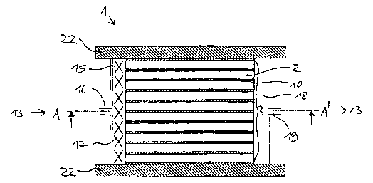
Fig. 2a illustrates a sectional view of a fuel cell system according to the
invention in stacking direction. Between the individual fuel cells 2 as well
sso as between the first and last fuel cells of the stack 3 and the respective
adjacent current collector on the end plate 22, there are provided inter-
mediate spaces 10 through which cooling medium 13 flows during
operation. On two opposing lateral faces of the fuel cell stack 3, there is
schematically illustrated a chamber-like space each. The space shown
sss to the left in Fig. 2a is the cooling medium distribution space 15 into
which a cooling medium inlet opening 16 opens and in which a cooling
medium distributing structure 17 is provided. The space shown to the
right in Fig. 2a is the cooling medium collection space 18 having a
cooling medium outlet opening 19. The fuel cell system is confined
s~o upwardly and downwardly by the two end plates 22 projecting beyond
the arrangement of fuel cell stack 3, cooling medium distribution space
15 and cooling medium collection space 18. Upon tightening together
the stack 3, cooling medium distribution space and cooling medium
collection space are simultaneously tightened as well. For sealing
s~s between the cooling medium distribution space 15 and the cooling
medium collection space 18, respectively, and the end plates 22, there is
preferably used a sealing agent that can be removed again without
damage to the connected parts, for example silicone, silicone adhesives
(/date/so52/8/53/53387/030205-trl-aDD~~.sdwJ 2003-02-70 74:58
CA 02420158 2003-02-20
23/36
or butyl caoutchouc, so as to permit maintenance work on the fuel cell
sao stack without any problem. The two end plates 22 have passages therein
(not shown here) for supplying fuel gas and oxidant to the fuel cell stack
and for discharging fuel gas and oxidant from the fuel cell stack. Inlet
openings and outlet openings for cooling medium into the cooling
medium distribution space or from the cooling medium collection space
sas may be provided in the end plates as well. Upon operation of the fuel cell
stack 1, cooling medium 13 enters into the cooling medium distribution
space 15 at the cooling medium inlet opening 16, flows through the
intermediate spaces 10 between the individual fuel cells 2, along the
surfaces of the pole plates 5, 6, and reaches the cooling medium
sso collection space 18 and leaves the same again though the cooling
medium outlet opening 19. Spacer structures 11 are illustrated in the
intermediate spaces 10 by way of broken lines.
Fig. 2b shows a sectional view of the fuel cell system 1 of Fig. 2a along
sss the line AA', i.e. a section through an intermediate space 10 between two
individual fuel cells 2 perpendicular to the stacking direction. The inter-
mediate space 10 has spacers 11 therein, shown in the form of parallel
lines, which at the same time act as electrical connectors between the
pole plates of the adjacent individual fuel cells. The cooling medium 13
goo flows through the intermediate spaces 14 between the spacers 11. On
two opposing lateral faces 23, 23' of the fuel cell stack, there are
provided a chamber-like cooling medium distribution space 15 and a
chamber-like cooling medium collection space 18 each, which are illus-
trated in Fig. 2b as being of identical design, which however is not
Los cogently necessary. For forming the cooling medium distribution space
and the cooling medium collection space, a sheet material piece of U-
shaped cross-section is slid over the lateral faces 24, 24' of the stack in
the manner of a bracket each, and a sealing agent 26 is applied to the
points of contact between cooling medium distribution space and stack
[/data/so52/8/53/53387/030205-ul-appli.sdw] 2003-02-10 14:58
CA 02420158 2003-02-20
. 24/36
~~o lateral faces 24, 24'. On two opposing edges of each intermediate space
10, there is provided a strip of sealing agent 25 each, sealing the inter-
mediate space 10 towards the outside. The sealing agent 25 each
extends over the entire length of the intermediate space, and thus also
into the region covered by the seals 26. The stack lateral faces 24, 24'
~1s thus consist here of sealing agent 25 and individual fuel cell face sides
in
alternating fashion.
In operation, cooling medium 13 thus flows through the cooling medium
inlet opening 16 into the cooling medium distribution space 15 having
~ZO the cooling medium distributing structure 17 therein, enters the stack 3
at
the stack lateral face 23, flows through the cooling medium flow paths
14, leaves the space on the opposite stack lateral face 23', enters the
cooling medium collection space 18 and leaves the same through the
cooling medium outlet opening 19. Owing to the sealing, agent 25, there
~2s is no cooling medium leakage occurring at the lateral faces 24, 24'.
In a section of the embodiment shown in Fig. 2b along the line BB', the
representation according to Fig. 2a results.
~so Fig. 2c also shows a section through a fuel cell system according to the
invention in the plane of an intermediate space between two individual
fuel cells, but in the instant case the cooling medium distribution space
15 and the cooling medium collection space 18 are arranged on the
same lateral face 23 of the fuel cell stack. Thus, a combined distri-
735 bution/collection space is formed which, seen from outside, has the
same shape as a cooling medium distribution space and collection
space, respectively, according to Fig. 2b. A thermally insulating partition
8 extending approximately centrally in stacking direction separates the
space into two segments that are each accessible separately, the
Sao segment of the cooling medium distribution space 15 through the inlet
[/data/so52/8/53153387/030205-trl-appli.sdwj 2003-02-t0 14:58
CA 02420158 2003-02-20
25/36
opening 16 and the segment of the cooling medium collection space 18
through the outlet opening 19. By means of the spacer structure 11 there
are formed cooling medium flow paths 14 having a curved shape and
directing the cooling medium from its entry on one half of the stack
7a5 lateral face 23 to its exit on the other half of the stack lateral face
23,
distributing the cooling medium as uniformly as possible in the interme-
diate space. On the remaining lateral faces 24 of the stack, there is
provided a sealing agent strip 25 at the edge of each intermediate space,
so as to prevent leakage of cooling medium.
750
Figs. 3a and 3b each illustrate a wall for a cooling medium distribution
space 15 of U-shaped cross-section according to the invention. A
cooling medium collection space 18 of course may be of identical
design. On the inside of the U-legs engaging over the stack lateral faces
755 24, 24' upon attachment of the wall of the cooling medium distribution
space to the fuel cell stack 3, there is provided a sealing agent 26 for
laterally sealing the cooling medium distribution space. In the embodi-
ments according to Figs. 3a and 3b, the stack end plates 22 are also used
to form the cooling medium distribution space. When the end plates
7so project sufficiently beyond the basic area of the fuel cell stack 3, as
indicated in Figs. 2a to 2c, the end plates may simply be applied to the
U-shaped sheet material piece and the resulting edges may be sealed
by a sealing agent 27 as shown in Fig. 3a. When the end plates on the
lateral faces 24, 24' of the stack 3 do not project beyond the basic area of
7s5 the stack, the sealing agent 27 for sealing to the stack end plates may be
applied to the insides of the U-shaped sheet material piece as shown in
Fig. 3b.
Another modification of a connection between an end plate 22 and the
77o sheet material constituting the cooling medium distribution space is
illustrated in Fig. 3c. The end plates 22 have a peripheral groove formed
(/data/so52/8153/53387/030205-trl-sppli.sdwJ 2003-02-10 14:58
CA 02420158 2003-02-20
26/36
therein that corresponds to the U-shaped sheet material piece, with the
base of the groove necessarily being slightly larger than the wall
thickness of the sheet material piece. A sealing agent is introduced into
ns the groove, and then the sheet material piece is lowered or pushed into
the sealing agent.
Figs. 4a and 4b illustrate a preferred embodiment of the decoupling
feature of the cooling medium circuit from the circuits carrying fuel gas
Sao and air/oxygen, according to the invention. Between the membrane
electrode unit of an individual fuel cell and the anode-side and
cathode-side pole plates, there are provided seals each. Fig. 4a shows a
plan view of an anode side of a membrane electrode unit having a seal
36 towards the anode-side pole plate. Seal 36 surrounds an active
gas reaction region 34, but leaves free two mutually opposite corner portions
of the membrane electrode unit. The fuel gas supply 30 and the fuel gas
discharge 31 are within the active reaction region 34, whereas the
oxidant supply 32 and the oxidant discharge 33 are located outside of the
active reaction region 34. The oxidant supply and the oxidant discharge
~so are sealed with respect to the cooling medium 13 by seals 38 and 39.
Fig. 4b illustrates a corresponding arrangement on the cathode side. The
seal 37 between membrane electrode unit and pole plate delimits an
active reaction region 35. The oxidant supply 32 and the oxidant
ass discharge 33 are located internally of the active reaction region 35.
Oppositely arranged corner portions of the membrane electrode unit for
the fuel gas supply 30 having a seal 40 as well as the fuel gas discharge
31 having a seal 41 are arranged externally of the seal 37.
soo The corner portions of the membrane electrode unit arranged externally
of the seal 36 and the corner portions of the membrane electrode unit
arranged externally of the seal 37 do not overlap each other. This
[/data/so52/8!53/53387/030205-trl-eppli.sdw] 2003-02-10 14:58
CA 02420158 2003-02-20
. 27/36
arrangement ensures intersection-free supply and discharge of the
reaction gasses to the active reaction regions of the individual fuel cell
soy without contact to the cooling medium, but with the cooling medium
flowing around the supply and discharge means.
The construction according to the invention permits the use of electri-
cally non-conducting, weakly conducting or highly conducting fluid
ago media for cooling, since there is a complete separation and enclosure of
the cooling medium with respect to the active membrane zone and, if
necessary - in particular in case of highly conducting or aggressive fluid
media -, both the individual fuel cells and the fuel cell stack may be
provided with an electrically not conducting insulating layer or a
si5 protective layer that is resistant to the aggressive medium.
This results in a number of advantages:
The fuel cell stack may even be operated with such cooling media which,
a2o in case of direct contact with membrane, catalyst layer, gas diffusion
layer, sealing system and/or pole plates, could cause damage of the
same (e.g. oils, cooling water enriched with foreign ions (Cu2+, Ni2+) from
heat exchanger installations, cooling water with anti-freeze agent,
alcohols).
825
The fuel cell system can be made "winter-proof' by selecting a suitable
cooling medium; i.e. freezing of the fuel cells in a large range of
temperatures below freezing can be prevented e.g. by addition of anti-
freeze additives to the cooling medium.
a3o
Irrespective of this, the construction according to the invention, at least
when the same has a cooling jacket, is also significant in terms of safety
aspects when conventional cooling media are used, since the fuel cell
[/data/soSZ/8153!53387/030205-trl-aDP~~.sdw] 2003-02-10 14:58
CA 02420158 2003-02-20
28/36
system provides for inherent safety with respect to the leakage of fuel
s3s gas as the latter will be taken up completely by the cooling medium in
case of a leak and cannot escape to the environment.
Remarkable is also the technically very uncomplicated structure of the
system and the weight savings attainable, in particular when a combined
sao cooling medium distribution/collection space is employed.
Finally, the following aspects should be pointed out in addition which are
of relevance to the invention:
say The longitudinal axis of the fuel cell system may be vertical (as in the
embodiments illustrated), horizontal or also inclined. The cooling
medium preferably is a liquid cooling medium.
Udata/so52J8/53/53387/030205-trl-appli.sdw] 2003-02-10 14:58